ASC A-OH15 User manual
ご使用になる前に、正しく安全にお使い頂くためにこの取扱説明書を必ずお読みください。
特に「 安全に関する重要事項」の項は必ずお読みになり、正しくご使用ください。
そのあと大切に保管し、必要なときにお読みください。
Please read this instruction manual carefully to ensure that you use the Product
correctly and safely.
Read " Important Safety Instructions." Keep this instruction manual.
株式会社エーエスシー
製造元/ Manufacture
取扱説明書
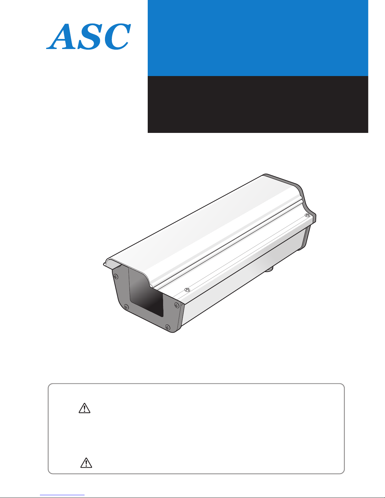
屋外用ハウジング
Product Instructions for
Outdoor Housing
A-OH15
修理及び機器に関するお問い合わせ先
Service and Technical Support
〒105-0001 東京都港区虎ノ門 3-16-9
Tel 03-5473-7627
Fax 03-5473-7628
URL:http://www.kk-asc.com
3-16-9, Toranomon, Minato-ku, Tokyo 105-0001, Japan
Tel +81-3-5473-7627
Fax +81-3-5473-7628
5975 Shiloh Road, Suite 103, Alpharetta, GA 30005
Tel 770-888-4674 · 1-888-988-4674
Fax 770-888-4675

11 22
1 取扱説明書を必ずお読みください。
2 取扱説明書をお読みになった後、いつでも見られる場所に大切に保管してください。
3 全ての警告・注意事項をお守りください。
4 取扱説明書に従ってください。
5 本器を水に近い場所でご使用にならないでください。
6 清掃の際は必ず乾いた布をご使用ください。
7 内部循環に関するファンヒーターを塞がないようにしてください。
8 熱を発生する源となるヒーターやストーブ等(アンプ類を含む)の近くに設置しない
でください。
9 アース付のコンセントの場合にアースを破壊する等の行為を行わないでください。
10 電源線は人が往来するような場所に敷設しないでください。
11 取り付けるためのビス等の材料は取扱説明書の指示に従ってください。
12 取り付ける金具は弊社のものを必ずご使用ください。
13 落雷の危険が予知される場合、また長期に渡り本器をご使用にならない場合は電源を
必ずコンセントから抜いてください。(またはブレーカーを切る)
警告
安全に関する重要事項
1) Read these instructions.
2) Keep these instructions.
3) Heed all warnings.
4) Follow all instructions.
5) Do not use this apparatus near water.
6) Clean only with dry cloth.
7) Do not block any ventilating openings. Install in accordance with the
manufacturer's instructions.
8) Do not install near any heat sources such as radiators, heat registers, stoves
or other apparatus (including amplifiers) that produce heat.
9) Do not defeat the safety purpose of the polarized or grounding-type plug.
A polarized plug had two blades with one wider and the other.
A grounding type plug has two blades and a third grounding prong.
The wide blade or the third prong are provided for your safety.
If the provided plug does not fit into your outlet, consult an electrician for
replacement of the obsolete outlet.
10) Protect the power cord from being walked on or pinched particularly at
plugs, convenience receptacle, and the point where they exit from apparatus.
11) Only use attachments/accessories specified by the manufacturer.
12) Use only with the bracket specified by the manufacturer, or solid with the
apparatus.
13) Unplug this apparatus during lightning storms or when unused for long period
of time.
IMPORTANT SAFETY INSTRUCTIONS
WARNING

33 44
警告
安全のために必ずお守りください。
● 本製品(電気・電子機器)は、一般廃棄物として投棄できません。
電気製品の投棄については、お客様がお住まいの地域の規則に
従ってください。
製品の廃棄とリサイクル
● 雨天時はアクリルウィンドウに水滴が付着し画像が見づらくなることがあります。
● また環境によりアクリルウィンドウが汚れますと画質が低下いたしますので定期的
に清掃を行ってください。
● 日本国内においてのみAC100Vタイプのファンヒーター回路が使用できます。
ヒーター動作時には20W消費いたしますので、それに適したケーブルと電源の
施工が必要です。
● 電源回路にはブレーカーやヒューズ、接地などの保護対策をしてください。
保護対策をしないと火災、感電の原因になります。
● AC24V及びDC12Vの電源をご使用になる場合はPSEマーク付のものをご使用
ください。
● AC24V及びDC12Vのタイプヒーターの場合は動作時に25W消費いたしますので
カメラとの合計でそれに適したケーブルと電源ユニットの選定が必要になります。
● 使用環境は屋外一般を想定して保証しているものであり、通常−20℃〜+40℃の
温度範囲となります。
● 屋内のように高温や高湿度に常時さらされる環境での保証はしておりません。
また、各々のカメラの仕様によりその限界温度・湿度仕様が異なりますので事前に
よくカメラメーカー及びハウジングメーカーである弊社と仕様について確認する必
要があります。
入力電源に関する注意
基本使用環境
アクリルウィンドウの清掃
● 製品の内部を分解したり、改造や加工をしないでください。
機器の破損や落下、浸水、火災、感電の原因になります。
● 雨天の日の施工は行わないでください。
感電の危険や、アクリルウィンドウの曇りの原因になります。
● 据付工事は、販売店または専門の工事店が実施してください。
間違った工事は故障や事故の原因になります。
● カメラハウジングは強度が十分にあると認められる壁面及びポールに確実に取り
付けてください。
●
M6または1/4のステンレスボルト4本で確実に固定してください。
雨天時の施工禁止
施工
取付の強度を確保する
機器の改造の禁止
Table of contents
Popular Camera Accessories manuals by other brands


Trojan
Trojan GC2 48V quick start guide

Calumet
Calumet 7100 Series CK7114 operating instructions

Ropox
Ropox 4Single Series User manual and installation instructions

Cambo
Cambo Wide DS Digital Series Main operating instructions

Samsung
Samsung SHG-120 Specification sheet

Ryobi
Ryobi BPL-1820 Owner's operating manual