Operating Instructions Ascoline 700, AEH 35x
ascobloc Gastro-Gerätebau GmbH 01156 Dresden, Grüner Weg 29 Germany
Tel. +49 351 4533-0 Fax +49 351 4537-339 E-mail: service@ascobloc.de AEH 35x_d.doc, Status: 19.04.2013
Subject to change without notice!
4
Credit cards, telephone cards and similar objects can be made useless if they come close to the cooking hobs.
The air slits under the control panel and in the intermediate floor may not be altered in cross section. Do not hang
any cloths over the panel. This could interfere with the internal cooling air system. The appliance has an inlet air
filter. Despite that, you must ensure that the incoming air contains no grease from other appliances that could be
drawn into the induction appliance (e.g. from nearby deep fat fryers and grilling plates). The temperature of the air
being drawn in must be below +35°C.
Should a crack form in the glass ceramic surface, the appliance must disconnect from the mains supply
immediately and the competent repair service informed.
Before repair work is started, the equipment must be disconnected on all poles from the power (using isolating
equipment in the customer's supply, e.g. contact breakers).
3.3 Instructions for transport
Transport ascobloc equipment only in the original packaging. This avoids unnecessary damage and expense.
Check equipment for damage.
Do not lift or shift the appliance by holding the top plate, the bottom edges at the sides of the appliance or by the
door handles. The bottom edges at the front and rear of the appliance are provided for this.
3.4 Instructions on installation
The appliance is wired up in the factory as far as the connector. All connection work must be carried out by an
authorised specialist company. Allow the technical experts to look at these documents. The legally acknowledged
regulations (Germany VDE, Austria ÖVE, Switzerland SEV etc.), and the connection requirements of the local
electricity utility are to be observed.
Before beginning the installation work, it should be checked that the mains voltage, mains type and the current
rating of the circuit breaker match the values given on the name plates. An isolating device in the customer's
scope of supply that is effective on all poles must be provided, e.g. contact breakers with at least 3 mm contact
gaps, so that the equipment is disconnected from the power supply during repair and installation work.
Connection to an equipotential bonding system is available. Make the connections in accordance with the local
regulations.
Mains cables are not to be sharply bent, crushed or damaged by sharp edges. Mains cabling are to be so laid
that contact with hot parts cannot occur. The power supply cable must be led through the equipment, fully
sheathed, from the screwed connection to the entry of the terminal. The appliance is intended for a permanent
connection; connection via plug and socket is not permitted
4 Installation
4.1 Setting up
Do not set up the equipment next to walls, kitchen furniture, Decorations or similar which are made of flammable
materials. Otherwise there is danger of fire. See connection diagram with equipment description for minimum
distance. Local fire protection regulations must be kept to absolutely!
It is of importance that the equipment be set up absolutely horizontal (use spirit level for alignment) so that the
doors can be opened and closed without any problem and that they seal tightly when closed. Equipment with
adjustable feet can easily compensate for unevenness in the floor (+/- 20 mm) by turning the bottom ends of the
feet. If set up on a plinth, this is to have shims fitted underneath to compensate for unevenness, if required.
4.1.1 Free-standing set-up
If the equipment is to be set up on its own, suitable means are to be used to protect it against tilting and shifting.
4.1.2 Setting them up in groups or blocks
When setting up in groups or blocks, the equipment must be joined together by connecting elements provided for
this purpose. This is for the sake of hygiene. Observe equipment setting up sheets or assembly diagram
(data sheet in annex).
4.2 Connections
Details of connections for the media can be taken from the accompanying connection diagram and equipment
description. Check whether the size and position of the electrical connections of the customer side correspond to
the information in the connection plan, equipment description or installation plan
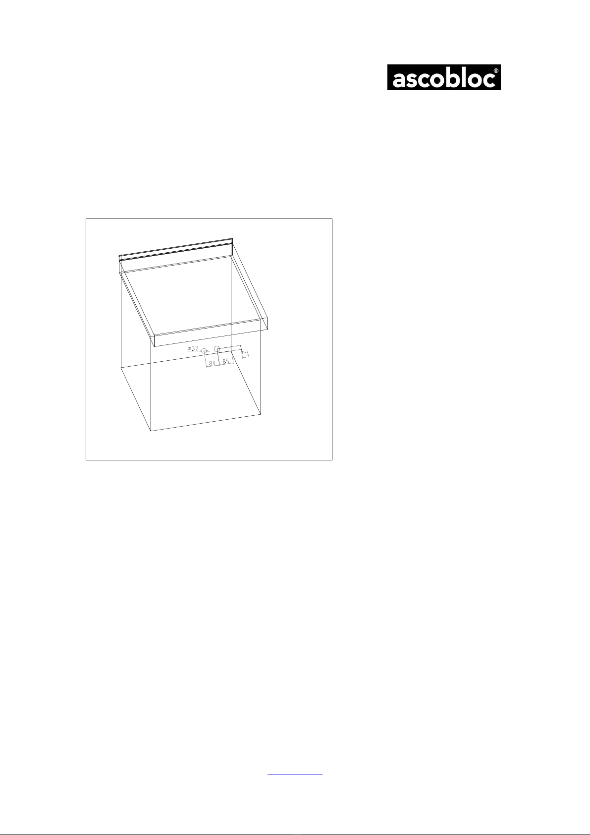
The terminal box for the connections is located behind the front panel A (see data sheet). Make the connections
as shown in the annex or in the connection diagram accompanying the equipment. The number of the connection