Operating Instructions for Ascoline 700, AGL20x.x, 40x.x, 60x.x
ascobloc Gastro-Gerätebau GmbH 01156 Dresden, Grüner Weg 29 Germany
Tel.:
+49
351
4533-0
Fax
+49
351
4533-433
E-mail:
[email protected] Version: 07/07/2015 Subject to change without notice!
2
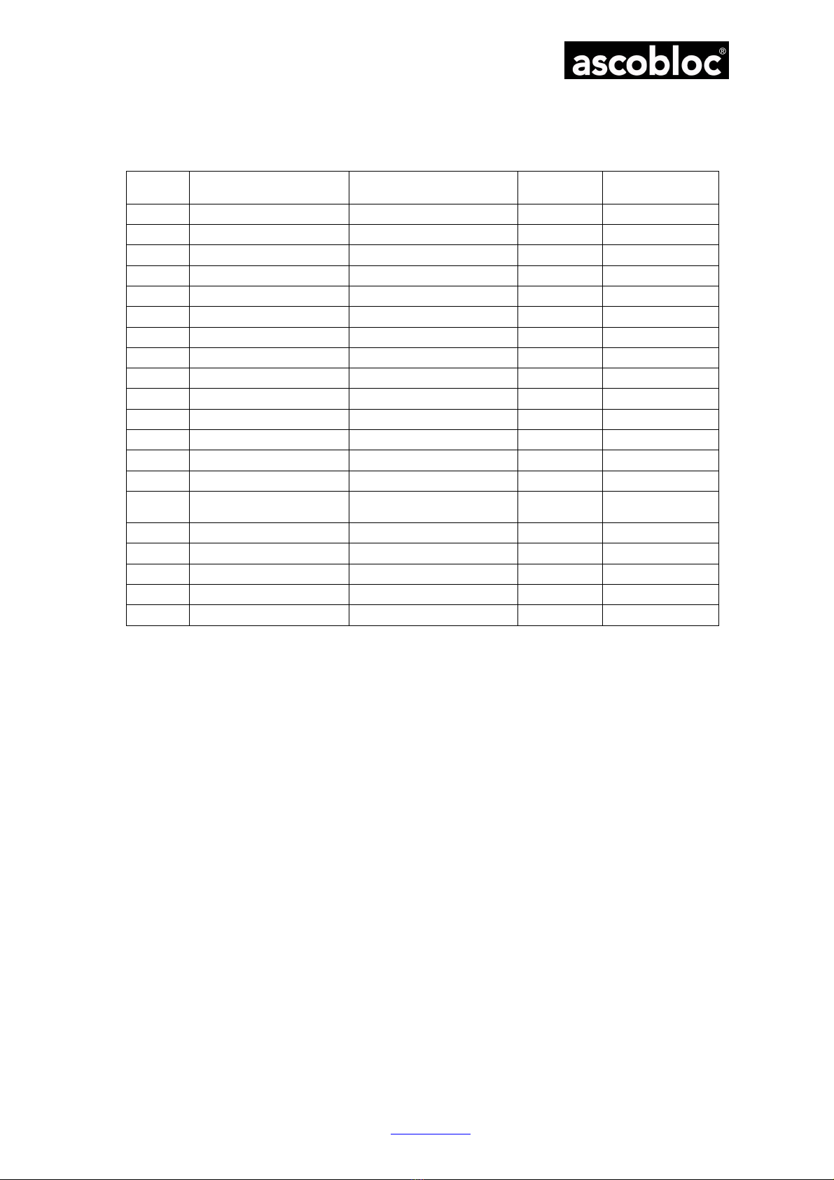
2 Details of the Appliance
AGL 200.100 Lava Stone Grill, round bar grid, 1 burner 7386.201
AGL 200.200 Lava Stone Grill, V-grid, 1 burner 7386.202
AGL 400.100 Lava Stone Grill, round bar grid, 2 burners 7386.401
AGL 400.200 Lava Stone Grill, V-grid, 2 burners 7386.402
AGL 600.100 Lava Stone Grill, round bar grid, 3 burners 7386.601
AGL 600.200 Lava Stone Grill, V-grid, 3 burners 7386.602
AGL 208.100 Lava Stone Grill, round bar grid, 1 burner 7385.201
AGL 208.200 Lava Stone Grill, V-grid, 1 burner 7385.202
AGL 408.100 Lava Stone Grill, round bar grid, 2 burners 7385.401
AGL 408.200 Lava Stone Grill, V-grid, 2 burners 7385.402
AGL 608.100 Lava Stone Grill, round bar grid, 3 burners 7385.601
AGL 608.200 Lava Stone Grill, V-grid, 3 burners 7385.602
(See data sheet in annex for technical data)
3 Instructions on Safe-handling of the Appliance
3.1 General Instructions
The equipment is a technical appliance that is only intended for commercial use.
The AGL lava stone grills are used for preparing food on a commercial scale.
The appliance is not suitable for spatial heating or for warming up other materials – apart from those
normally used in grilling.
Ventilation of the work rooms complying with the regulations is to be ensured.
The employers' liability insurance association (BG) rules "Working in Commercial Kitchens" of the
"Food Processing Industry" expert committee of the BG Central Office (BGR 111) are to be observed
when setting up and operating equipment.
Technical modifications to the appliance by unauthorised persons without written permission from the
manufacturer completely nullify any claims under the guarantee and invalidate any claims in respect of
product liability.
These instructions are to be made known to the members of staff affected in the context of an operating
directive.
3.2 Safety instructions for operating, cleaning and repair
Overheated fats and oils can be self-igniting. The preparation of food using fats and oils should not be left
unsupervised. Never try to extinguish fat or oil using water!
Several parts, such as the top plate, get very hot due to the high temperatures needed for grilling. Protect
yourself by only touching the control elements provided and by wearing clothing that prevents direct skin
contact.
The system may only be operated and cleaned by personnel who have received appropriate instructions.
Maintenance and repair may only be performed by qualified specialists who have received training.
The manufacturer cannot be made liable for damage due to inexpert connection and handling. Claims
under the guarantee in such cases are null and void.
Gas appliance safety:
All subsequent constructional modifications to rooms housing the appliances which impair the adequate
supply of combustion air to the gas appliances are not permitted, since these not only have an impact on
the correct functioning of the appliances but can also have fatal consequences for those working there.
If there is a smell of gas, do not light a flame! Immediately close the gas supply valve on the customer
side! Open windows, check whether there is a leak. If the cause cannot be identified or remedied,
immediately inform a gas installation firm or the gas supply utility!