ASHAPOWER ROVER-5000LV-48V User manual

1
MODEL: ROVER-5000LV-48V
I N N OV AT I NG
TOMORROW
SOLAR MPPT PCU
USER MANUAL
ISO
CERT IFIED
900 1: 201 5
HS
COMPLIANT
Vers.5.1
HIGH PERFORMANCE WITH LOW ENERGY CONSUMPTION
48V
-5KVA
3.5KW PV PANEL
60AMP/185Voc
MPPT SCC
INVERTER
GRID CHARGER
20AMP
No load DC current
0.7A 0.3A
High grade
CRNO laminated
Pure Copper transformer
70 Micron High grade PCB
0.8
Constant output power factor
(
5
000VA = 2400W max. O/P load)
Pick & Place type circuit
Design for quick service
Maximum MPPT tracking
Efficiency up to 98.9%
Constant output Voltage
(222V) even on heavy loads
User configurable
Function settings
PV Panel Voc upto
185
Volt
-
+
Charging Priority control facility
Grid charging ON-OFF control
Grid priority,Solar priority

stylish design : Makes you proud to place the device in a visible place at your
home/office
*Unique ZMPT based isolated grid sensing : Reduces chances of MOSFET
failure on lightning & external surges.
*Forced grid to solar shifting facility: Helps customer to use maximum solar
power *Sleek and stylish design : Makes you proud to place the device in a
visible place at your home/office
power *Sleek and stylish design : Makes you proud to place the device in a
visible place at your home/office
2
ASHAPOWER
SOLAR MPPT PCU
MODEL: ROVER 5000LV-48V
UNIQUE FEATURES
185Voc-60Amp-3.5kw PV load and 4Kw Inverter combination assure continuous
day time heavy load operation without disturbance to batteries
High power inverter and MPPT integration
Standby zero grid power consumption
Once the battery is fully charged frequent relay controlled isolation of grid power
from charging transformer ensures standby zero grid power consumption saving electricity
Constant noise free DSP pure sine wave output
Ensures best life and flicker free working of digital equipments
Large 4Line multifunctional LCD front panel display
Gives detailed and clear system information at a look
Soft front panel all function control switches
Helps easy finger tip system control and function settings
Pure Copper Transformer with high grade Lamination
Ensure minimum no load DC current (0.8 PF) and saves generated solar power
Intelligent true multi stage smart solar and grid charging
Ensures prolonged battery backup and life
Battery grid charging even at low grid voltage
Suitable for places with low grid voltage areas
High over load and surge load handling capacity
Trouble free running of loads with initial heavy input surge
MCB short circuit protection for grid power
Ensures system safety and avoids frequent fuse changing
Over load,surge and short circuit protection
Protection for internal component failure
All type battery compatibility
Supports tubular lead acid, flat,SMF,Gel,batteries. Branded LiFeO4
batteries with BMS can be connected with the support of the battery supplier
Unique ZMPT based isolated grid sensing
Reduces chances of MOSFET failure on lightning and external surges
Forced grid to solar mode shifting facility
Helps customer to use maximum harvested solar energy
Bulk,Absorption,Float (User configurable battery charging voltage)
Customer control over grid charging ON/OFF option.
Blocks battery charging from grid power saving electricity
User selectable solar priority and grid priority charging modes
Helps customer to select charging mode as per the power conditions of the site
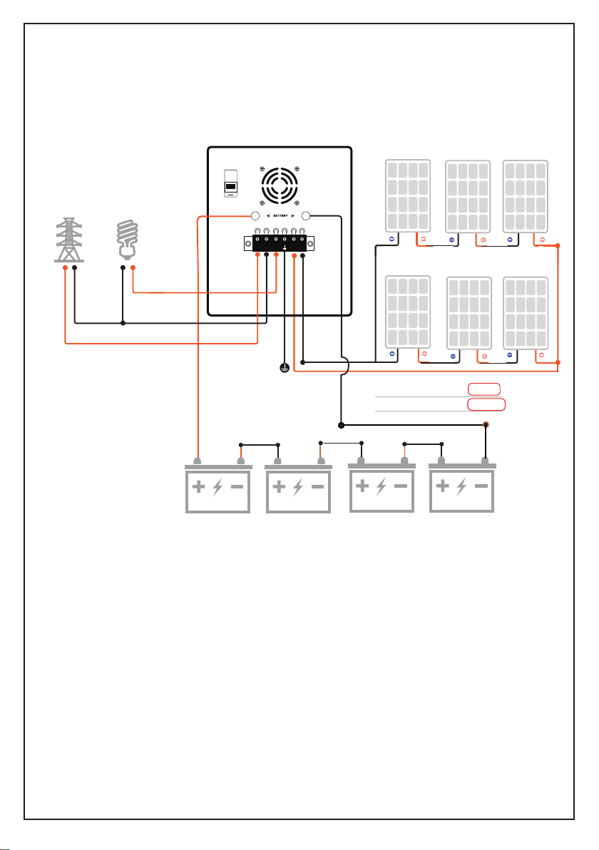
ASHAPOWER SOLAR MPPT PCU ROVER-LV-5000- 48V is a Premium quality
high power Solar energy extractor for your Home/Office having a connected
load of 4000Watts. It can be loaded with Air conditioner, Induction cooker, Fans,
LED lights, Computer, LED TV, Washing machine, Laser printer, Refrigerator,
Iron box, and an Induction motor pump when used with 4500 watts Solar PV
panels and 48V / 200Ah batteries. The integration of an efficient MPPT SCC
(185Voc/60AMP/3.5kwp), 48V/4000W pure sine wave inverter, powerful grid
charger and high performance with low energy consumption makes it unique in
its class.

Nominal Battery Voltage
Maximum solar Charging Current
No load battery Power Consumption
Overload Protection From PV Panel
Over Charge Protection from grid and solar
Panel Reverse Polarity Protection
Battery Reverse Polarity Protection
Dimensions – L x W x H (cm) 47.7cmx25.3cmx39.2cm
Connectors
Display
48V DC
98.9%
Humidity 0 to 90% RH (No dew)
Operating temperature -20 degree to 65 degree C
-30 degree to 80 degree C
Storage temperature
Optional
YES
YES
YES
4line LC Display
Net Weight (Kgs) / Gross Weight (Kgs) 36.9kg/39.7kg
Solar MPPT battery charging stages Bulk-Absorption-Float
6Way Input/Output Terminal block
Max. Applicable PV Panel Load on MPPT
Maximum MPPT tracking efficiency
3000wp/185Voc - 3500wp if Voc <140V
Max. Applicable PV Panel Voc
Maximum grid battery charging current
4 AMP TO 15AMP
(selectable)
Standby grid Power Consumption Zero at idle stage
GRID POWER ON BATTERY LOW OVER LOAD
FORCED
SHIFTING
DSP SINE WAVE
SOLAR MPPT PCU
LOAD ON SOLAR GRID CHARGING SOLAR CHARGING
4x16 LCD DISPLAY
LED INDICATORS
FUNCTION KEYS
COOLING FAN
AC MAINS MCB
BATTERY DC INPUT
CONNECTION TERMINAL BLOCK
7
6
5
4
3
2
1
2
1
35
7
6
PHASEONLY
SOLARPANEL
EARTH
+_
+_
GRID
PHASE
IN
GRID
NEUTRAL
IN
GRIDPOWERON BATTERYLOW OVERLOAD
FORCED
SHIFTING
DSPSINE WAVE
SOLARMPPT PCU
LOADONSOLAR GRID CHAR GING SOLARCHARGING
4
INVERTER
OUTPUT
TO LOAD
0.7AMP +.3
-
Grid power battery charging stages Bulk-Float
GRID INPUT
3
60Amps (configurable)
BATTERY INPUT
48V/3200W INVERTER + 60AMP/185Voc/3kwp - MPPT SCC
KNOW YOUR DEVICE
ASHAPOWER SOLAR MPPT - PCU ROVER-5000-48V
185V
48V

GRID POWER ON BATTERY LOW OVER LOAD
FORCED
SHIFTING
LOAD ON SOLAR
GRID CHARGING ON SOLAR CHARGING ON
2
1
3
4x16 LCD DISPLAY
LED INDICATORS
FUNCTION KEYS
3
2
1
FRONT PANEL INDICATIONS
INNOVATING TOMORROW
SOLAR MPPT PCU
4

5
7
6
PHASE ONLY
SOLAR PANEL
EARTH
+
_
+_
GRID
PHASE
IN
GRID
NEUTRAL
IN
4
INVERTER
OUTPUT
TO LOAD
COOLING FAN
GRID POWERMCB
BATTERY DC INPUT
CONNECTION TERMINAL BLOCK
7
6
5
4
BACK PANEL CONNECTORS
GRID IN MCB
5
BATTERY INPUT
SOLAR INPUT
GRID & SOLAR CONNECTION TERMINAL BLOCK
(48V)

EXAMPLE FOR PV PANEL GROUPING
ASHAPOWER SOLAR PCU
48V/3200W/ 60AMP/185Voc
50 Voc,500W PV PANELS x 6
(
4
X 12V BATTERY / 200 AH)
+_
48
V B
ATTERY BANK
Total PV Panel Voc
150V
3000 W
Total PV Panel Load
Max PV.Panel Applicable in Watts : 3000w
Max PV.Panel Voc : 185V
SOLAR PANEL
EARTH
INVERTER
OUTPUT
TO LOAD
+_
+_
GRID
PHASE
IN
GRID
NEUTRAL
IN
PNP N
NP P
LOAD
GRID
POWER
6
GRID IN MCB
If Voc is below 140V 3500W panel can be connected
ASHAPOWER SOLAR-MPPT-PCU-ROVER-5000LV -48V CONNECTIONS

stylish design : Makes you proud to place the device in a visible place at your
home/office
*Unique ZMPT based isolated grid sensing : Reduces chances of MOSFET
failure on lightning & external surges.
*Forced grid to solar shifting facility: Helps customer to use maximum solar
power *Sleek and stylish design : Makes you proud to place the device in a
visible place at your home/office
power *Sleek and stylish design : Makes you proud to place the device in a
visible place at your home/office
GRID (AC MAINS) MODE PARAMETERS
GRID (AC MAINS) MODE BATTERY CHARGING PARAMETERS
Battery Charging Algorithm Bulk,Absorption,Float
Constant Charging Current 8 AMP (Selectable)
Default charging Priority Solar priority
Float Charging Voltage 13.8VX4 =(55.2V) Volt (user selectable)
Battery Bulk charging voltage 14.4VX4=57.6V) (user selectable)
Inverter Output Volage 222 Volt
Inv Output Frequency 50 Hz
Inverter Surge Rating for 2 Second 250 %
Battery high voltage trip 66 Volt
Battery Low Warning Level 44 Volt
Battery Low Trip Level 43.2Volt
Overload Warning Level 95 %
Overload Trip Level 100 %
Inverter mode audio alarm Buzzer beep
INVERTER (BATTERY) MODE PARAMETERS
Inverter Power factor 0.8
Inverter Output Wave form DSP pure sine wave
Typical transfer time ≤20 m second
Mains detection delay 10 Seconds
Input mains high cut voltage (Wide input) 280V (Selectable)
Input mains low cut voltage (Wide input) 100V (Selectable)
Input mains high restore voltage (Narrow input) 260V
Input mains low restore voltage (Narrow input) 180V
Grid input voltage range 100V-300V Volt
Grid input requency 50 Hz
MPPT Max Voc 185 Volt
MPPT Max Output Current 60 AMP
Solar battery Charging Algorithm Bulk,Absorption,Float
Default solar float charging voltage 13.8VX4 =55.2V) (selectable)
Default solar Absorption charging voltage 14.1VX4 =(56.4V (selectable)
Default solar Bulk charging voltage 14.8VX 4=59.2V (selectable)
MPPT SCC PARAMETERS
MPPT Max PV Panel load 3000wp/185Voc, 3500wp if Voc below 140V
7

Battery bank Voltage
Mains input Voltage
Inverter output frequency
Inverter Output Load %
Battery charging current from grid
Grid bypass status
Inverter ON/OFF Status
Warning Messages Bat low/Overload
Trip Messages
LCD DISPLAY INDICATIONS
Grid charging ON/OFF status
LED INDICATIONS
Grid power presence Red Grid power LED ON
Battery grid charging Yellow Grid Charger LED ON
INV Std by on Mains Green Inverter ON LED Blink
INV load on Battery Green Inverter ON LED steady
Over load Warning Red Overload LED ON
Overload Trip Red Battery low LED ON
Battery Low Warning Red Battery low LED ON
Inverter output Voltage
Solar charging Amp
Solar PV Panel watts
Solar PV Panel voltage
IMPORTANT GENERAL ELECTRICAL SAFETY PRECAUTIONS
Lead Acid Batteries Produce Hydrogen Gas Which is Highly Flammable
1) Never use a flame or any kind of spark producing device near fully charged batteries as it may cause
an explosion of the batteries and fire hazard (eg: Checking battery water level under a candle flame,
spark from metal cutter or spark from loose contact of battery connecting wires).
2) Maintenance of the batteries and pv panel array at regular intervals make the solar power system
trouble free and fresh.
3) Solar panels should be grouped in such a way that the maximum Open Circuit Voltage (Voc) of the
panels connected in series should not exceed the Maximum PV panel voltage recommended for each
Battery Banks.
4) Safety precautions must be taken while grouping and connecting PV panels to the charge controller
with high Voc input. (500 Volt DC current from the PV panel is highly dangerous. Never touch the
terminals without safety glows).
5) Extreme care should be taken while connecting High voltage solar power systems.
6) Earthing and wiring of high power solar system must be done under the supervision of a qualified
electrical engineer.
7) Never connect the PV panel connection to the battery input or the connection of the batteries to the
PV input.
8) Never connect any of the grid line to any of the DC (PV or Battery) connection terminals.
9) The installation and use must comply with the local safety instructions and standards in force.
10) We disclaim all responsibility and liability for damage, costs or losses resulting from an installation
that does not comply with the instructions, a faulty operation or inadequate maintenance.
11) The use of the
Home UPS
is in any case under the responsibility of the customer.
12) This equipment is neither designed nor guaranteed to installations used for vital medical care nor any
other critical installation entailing potential risks of damage to people or to the environment.
8
Solar charging Blue LED ON and steady
Solar ready (load on solar) Green load on solar LED ON and steady
( Red grid power ON LED blinking)

9
ASHAPOWER SOLAR-PCU INSTALLATION & OPERATION GUIDE LINES
1) Battery bank setup :
25
sqmm/16sq
i
nter
li
nking
cables to join the batteries
and
tight them
well.
Check each
battery
separately for specific gravity,
same terminal
volt
and good backup
Do
not use old
and new batteries
together,
either in
parallel or in series.
distance from the
wall.
in the circuit of o grid power plant, under the guidance of a qualified electrical engineer/electrician for safety
3)
Place of Installation
:
4) DCDB / ACDB & Surge protectos :
Place the solar PCU on a fixed stand in a well ventilated area keeping a 6 inch
It is recommended to connect DCDB / ACDB & lightning surge protectors
Avoid
exposure to
rain,
dusty area, direct sunlight or
in
area having high temperature.
Now Connect the battery
wires with correct polarity to the connection
terminal blockof the device
(Reverse polarity
will spoil the device)
and long life of the power plant. Never use substandard electrical materials for wiring.
2)
PV panel grouping: Group the
PV panel array using
standard
s
olar MC4 connectors and
parallel
connectors as to the recommended grouping example chart provided. Good
quality weather proof
solar
DC cables must
be used
(6sqmm,10sqmm)
Use
LCD display shows battery voltage and default function parameters.
PV panel voltage and polarity is correct solar charging starts indicating SOLAR CHARGING LED
glowing ON.
Connect the cables
from PV
panels
to the
solar
positive
and
negative
terminals of
the solar PCU.
If
the
When
the connected
battery
vo
l
tage
reaches
GRID
to
SOLAR
preset vo
l
tage
(default
14.2V)
LOAD ON SOLAR
glows
ON
indicating
the
battery is nearly
full
charge
and
ready to
use
the
connected
indicator LED
When phase and neutral of grid power is connected to the concerned grid terminals
,GRID POWER ON
indicator
glows ON.
inverter load.
Quick customer settings menu is provided with 6 options
1) UPS / INVERTER mode ON/OFF selection
2) Grid Charging ON/OFF selection and Grid and solar charging priority selection.
GUIDE LINES FOR QUICK CUSTOMER SETTINGS AND MAIN TECHNICAL SETTINGS
Two priority charging options are given.
Solar charging priority and grid charging priority
If Solar priorityis selected, battery charging will be from solar power.If the battery terminal volt is below
the inverter low warning level (10.7default for 1 battery) grid power is also used for boosting the batteries.
When solar power is not available battery charging will be fully from grid power in 8 amps (default)
If Grid priorityis selected device charges the battery both from grid and solar power simultaneously
3) Grid bypass ON/OFF Selection and Automatic grid to solar shifting selection
Three options are givn. If BV+PV+GRID option is selected system shifts to solar mode only if there is the
presence of grid supply,high battery terminal volt and solar PV presence.
If BV+PV option is selected system shifts to solar mode only if there is the presence of solar PV and
high battery terminal volt. If BV option is selected system shifts to solar mode whenever the battery
terminal volt becomes high from any charging source.
giving priority to grid.eg.If the grid charger is preset to10 amps and solar charging current is available
above this value system charges battery drawing10 amps fully from grid power and available current
from solar.
4) Gri - solar-V (grid to solar shifting volt selection)
5) Sol - grid-V (solar to grid shifting volt selection)
Customer can select grid charging OFF option to avoid all kinds of grid power charging.
MODEL : ROVER-5000 LV-48V
6) Sol - grid-Kwh (solar to grid shifting based on Kwh) (for Lithium batteries)

10
What is INVERTER mode
In this mode device shifts the load to inverter when the mains voltage drops below 100V
If UPS mode is activated in low grid power voltage areas (below 190V) load will be working
on battery backup , resulting more grid energy consumption for charging.So it is better
to activate INVERTER mode for normal house hold equipments as fans LED lights,mixer grinder
washing machines etc.
Which mode is better for house hold equipments
What is CHARGER ON/OFF in quick settings menu
This option helps the customer to control charging of batteries (ON/OFF) from grid power saving
electricity.
MAIN TECHNICAL SETTINGS GUIDE LINES
How to enter main customer settings menu
Before entering settings menu ensure to OFF the device by pressing OFF button
Press OFF button again and press ENTER button also without releasing OFF button
for 3 seconds.With a beep sound device enters main settings mode.Cooling fan starts
functioning
Consecutive pressing of the ENTER button helps to go to next menu.If kept for
5 seconds system saves the changes and exits from settings menu.
Follow the settings table given below.Refer battery user guide lines also
before changing the settings.Remember blind settings will spoil
the device and batteries.
What is UPS mode in Quick settings menu.
UPS mode is to shift the connected load on inverter from grid power to battery
power when grid power drops below 190V.
Fluctuations on grid power badly affect digital equipments as computers.
When the device is used for digital equipments as computers select UPS mode
in ON position. In this mode device automatically shifts from grid mode to
inverter mode when AC mains voltage drops below 190V preventing frequent
computer system restarting.
When solar power availability is weak grid charging option must be kept in ON
Press OFF button on the front panel
Press and hold ENTER button for 3 seconds.Device enters Quick settings mode
Press ENTER button again to go to next menu
How to enter Quick customer settings menu
To exit Quick settings menu go through all menu or keep the device idle for 8 seconds
Select the required option by pressing ON/OFF button
displaying UPS mode ON/OFF selection option.Cooling fan starts functioning.
mode to avoid battery deep discharging.
What is SOL-GRD-Kwh in quick settings menu
20 MENU CUSTOMER RELATED SETTINGS ARE PROVIDED.
OTHER ADVANCED SYSTEM SETTINGS ARE PASSWORD PROTECTED.
When Lithium batteries are connected, solar to grid mode
shifting is better to control on the basis of average harvestable
units per day instead of battery terminal volt based shifting.
(The default value10KWH is an average of 3.5 units from 1KW
solar panels to 12V/200Ah battery)

11
MAIN FUNCTION SETTINGS
ASHAPOWER SOLAR PCU-ROVER-SERIES
6
BAT-TYPE
BATTERY TYPE SELECTION
1
MENU
DESCRIPTION
RANGE
MIN MAXDEFAULT
SETTINGS
TYPE OF
BAT-AH
BATTERY Ah. SETTING
INV-ABSN-V
ABSORPTION CHG. VOLT FROM GRID
INV-BULK-V
2
Limit the charging current to the battery if needed. (Inverters are always
5
BULK CHG.VOLT FROM GRID
SETTINGS
CUSTOMER
SETTINGS
CUSTOMER
SETTINGS
CUSTOMER
SETTINGS
CUSTOMER
( Lead acid,Gel,SMF) (0) MARKED
(Lithium,Nicad) (1) MARKED
"0"
--
Set the Ah of the connected battery bank to limit the bulk charging
time Eg: If 2 X 150Ah battery is connected in series set the value 150Ah
and if connected in parallel set as 300Ah
INV-OP-VOLT
OUTPUT VOLT OF THE
INVERTER
3
SETTINGS
CUSTOMER
Limit the grid charging float voltage recommended for the batteries.
222V 230V
210V
INV-FLOAT-V
FLOAT CHG.VOLT FROM GRID
4
SETTINGS
CUSTOMER
Limit the output voltage of the inverter.
Default value given is for C10 grade lead acid batteries.For SMF and Gel
batteries this value is between 13.0V to 13.8V.Refer bat.user guide
13V 16 .0V
13.8V
Limit the absorption charging voltage limit for the connected
battery.
13V 14V 16.5V
Limit the maximum bulk charging voltage recommended for
the batteries.Refer battery user manual for changing.Default value is for
C10 solar lead acid batteries.
13V
14.6V 16.5V
150Ah
Vers.5.1
Select optin "0" for Lead acid,SMF,GEL,batteries. Default battery type given is
Select option "1" for Lithium and Nicad batteries.
Ensure to connect LiFePO4 battery with the help of the battery supplier.
for Lead acid batteries.
Always use branded Lithium batteries with BMS.
Never enable Equalization charging for Lifpo4 batteries.
Ashapower recommends to change the charging parameters of this
device to make it compatible for LiFePO4 battery charging
10Ah 300Ah
INV-BAT-LOW
7
SETTINGS
CUSTOMER
Limit the minimum battery cut off volt limit
It is not recommended to keep this value below 10.5V per battery
9V
10.5V
16V
INV. BAT LOW VOLT

12
10
12
MENU
DESCRIPTION
RANGE
MIN MAXDEFAULT
SETTINGS
TYPE OF
8
9
11
MAIN FUNCTION SETTINGS
SETTINGS
CUSTOMER
SETTINGS
CUSTOMER
SETTINGS
CUSTOMER
ASHAPOWER SOLAR
-PCU ROVER-SERIES
INV-LOW WRN
BATTERY LOW WARNING
Limit the warning buzzer sound indication volt limit of the
connected battery
9V
10.7V
14.4V
INV-CHG-AMP
BATTERY GRID CHG AMP
Limit the charging current to the battery if needed. (Inverters are always
good gravity and backup
Refer battery user manual before changing the value
Maximum recommended charging current for a lead acid C10 grade
12V lead acid battery is 20% of the Ah .
connected to grid power and long time low amp charging ensures
4AMP 8AMP 20AMP
INV-M--LOW V
INV. GRID LOW VOLT
100V
Minimum AC mains voltage limit for inverter operation
Below this limit system goes to inverter mode to protect the load
80V 180V
INV-M-HIGH
INV.MAINS HIGH VOLT
Maximum AC mains voltage limit for inverter operation
Above this limit system goes to inverter mode to protect the load
240V 280V 280V
SETTINGS
CUSTOMER
INV-U-LOW-V
INV-UPS MODE LOW VOLT
100V
190V
200V
SETTINGS
CUSTOMER When AC mains voltage goes below the preset value system
goes to inverter mode from grid mode to protect the load
Vers.5.1
13
240V
280V
INV-U--HIGH
INV-UPS MODE HIGH VOLT
260V
SETTINGS
CUSTOMER When AC mains voltage goes above the set value system goes
to inverter mode from grid mode protecting connected load
14 INV-OVR-WRN
INV-OVER LOAD WARNING VOLT
50% 95%95%
SETTINGS
CUSTOMER When connected load on inverter goes above 95% system
gives over load warning sound to limit the load
15SOL-FLOAT-V
SOLAR CHG.FLOAT VOLT
SETTINGS
CUSTOMER
11V 13.8V 16V
Limit the float charging voltage recommended for the batteries. This
value varies in dierent types of batteries. Default value given is for C10
grade solar lead acid batteries. For SMF and Gel batteries this value is
between 13.0V to 13.8V. Refer battery user manual to change the value

13
16
MENU
DESCRIPTION
RANGE
MIN MAXDEFAULT
SETTINGS
TYPE OF
MAIN FUNCTION SETTINGS
17
ASHAPOWER SOLAR
-PCU- ROVER SERIES
11 V
14V
16V
SOL-ABSN-V
SOLAR CHG.ABSORPTION VOLT
SETTINGS
CUSTOMER
13V
14.
6
V 16.5V
Limit the maximum bulk charging voltage recommended for the
batteries.This value varies in dierent types of batteries.Default value
given is for C10 grade solar Lead acid batteries.For SMF and Gel
batteries this value is between 13.5V to 14.5V (Refer battery user manual
SOL-BULK-V
SOLAR CHG. BULK VOLT
SETTINGS
CUSTOMER
Vers.5.1
18
SOL-MAX-AMP
LIMIT TOTAL OUTPUT AMP
30A
50A 50A
Limit the total output current from the charge controller to the battery
and connected load
SETTINGS
CUSTOMER
19
Limit the charging current to the battery if needed. (maximum charging
current is recommended as 20% of the Ah of a single 12V lead acid battery.
Eg: for a 150Ah battery,30 ampere is the maximum charging current
recommended. Refer battery user manual before changing the value
BAT-MAX-AMP
LIMIT CHG. AMP TO BATTERY
40A
50A
SETTINGS
CUSTOMER
0A
20
CAL-PSWD-0
CAL-PSWD-1
CAL-PSWD-2
CAL-PSWD-3
TECHNICIAN
SETTINGS
ADVANCED SYSTEM SETTINGS
WITH PASSWORD
2
1FACT-RESET
RESTORE FACTORY SETTINGS
SETTINGS
CUSTOMER
-
0
To reset all settings to factory settings change the default
value from "0" to "1"
1
Limit the absorption charging voltage limit for the connected
batteries.Default value given is for C10 grade lead acid batteries.
(
whenever the battery voltage goes below the float voltage the
and ret
urns to float level and maintains acid gravity)
the device enters again to bulk and absorption charging modes

13
COMPARE THE UNIQUENESS OF ASHAPOWER MPPT PCU ROVER-5000LV-48V
No load DC current
0.7A 0.3A
High grade CRNO Laminated
Pure Copper transformer
70 Micron High grade PCB
0.8 Constant output power factor
(5000VA =4000W max. O/P load)
Pick & Place type circuit
Design for quick service
Maximum MPPT tracking
Efficiency up to 98.9%
Constant output Voltage
(222V) even on heavy loads
User configurable
Function settings
PV Panel Voc upto 185V
-
+
0.7 Output power factor
(5500VA = 3850W max. O/P load)
No load DC current 1.5A - 3A
Low grade CRNO Aluminium /
Copper transformer
35 Micron Low grade PCB
Bulky single mother board
Low MPPT tracking
Efficiency
Output Voltage fall on
Heavy loads
Non configurable settings
PV Panel Voc from 50 -
150 V
(ROVER-5000LV-48V
ASHAPOWER
OTHER BRANDS
Charging Priority control facility
Grid charging ON-OFF control
Grid priority,Solar priority
No priority control on charging
Table of contents
Other ASHAPOWER Inverter manuals
Popular Inverter manuals by other brands

Generac Power Systems
Generac Power Systems 004702-0, 004703-0, 004704-0, owner's manual

Deye
Deye SUN-3K-G05-1 user manual

Mitsubishi Electric
Mitsubishi Electric 800 Series instruction manual

Nibe
Nibe SOLAR 40 Installer manual

YASKAWA
YASKAWA VS mini C Series instruction manual

Generac Power Systems
Generac Power Systems Guardian 004373-2 owner's manual

Contour Hardening
Contour Hardening realpower owner's manual

Mitsubishi
Mitsubishi FR-A700 Series instruction manual

Huawei
Huawei SUN2000-4.95KTL-JPL1 user manual

SamplexPower
SamplexPower SSW-350-12A owner's manual

Mitsubishi Electric
Mitsubishi Electric FR-A700 Series INSTALLATION GUIDELINE

Deye
Deye SUN-30K-G041 user manual