ASHAPOWER SURYA-40 HV User manual

USER MANUAL
SOLAR MPPT
CHARGE CONTROLLER
MULTI VOLTAGE RANGE
ISO
CERTIFIED
9001:2015
R
O
HS
COMPLIANT
SURYA-40 HV
I N N OV ATING TOMORROW
12V/24V AUTO
VERS.7

SURYA-40 HV Vers.7
SOLAR MPPT CHARGE CONTROLLER
ASHAPOWER® SURYA-40 HV Vers.7 Solar MPPT Charge Controllers are multi voltage range devices with unique features.
The same device can be used for battery banks ranging from 1 Battery (12V) up to a battery bank of 2 batteries (24V) in
series. The battery voltage is selected by the device itself when connected to the battery bank. The device gives a
configurable charging current up to 40A. The Max PV panel input open circuit voltage up to 165V makes it easier to
group the panels conveniently. Also, sleek & stylish design of the product gives a better aesthetic view so that can be
mounted in a visible place inside your home or office.
SALIENT FEATURES
Compatible for 12V/24V battery bank
Auto-detection and setting of battery bank
4 stage smart charging for prolonged battery life
(Bulk-Absorption-Float-Equalization)
Programmable Initial limited ampere charging and
periodic or voltage controlled equalization charging
facility
Ultra-fast & efficient (98.9%) power point tracking
dsPIC33EP family micro controller based device
PV panel reverse polarity protection
Automatic disconnection of PV panels at night
Over voltage and overload protection from PV panels
Protection for battery against hardware failures
14 menu user programmable function settings and
inbuilt settings keys
Grid power control to the connected inverter
(SMU-SolarManagement Unit)
Forced grid to solar shifting facility
SPECIFICATIONS
Nominal Battery Voltage
Maximum Charging Current
Standby Power Consumption
Overload Protection From PV Panel
Over Charge Protection
Panel Reverse Polarity Protection
Battery Reverse Polarity Protection
Dimensions – L x W x H (cm)
Connector
Display
12V/24V
(Auto Setting)
98.9%
40Amps
<2W
Optional
YES
YES
YES
2 x 16 LCDisplay
Net Weight (Kgs) / Gross Weight (Kgs)
32x15x11
2.4Kgs/2.7Kgs
Battery charging stages
Maximum Tracking Eciency
Bulk-Absorption-Float-Equalization
Input/Output Terminal block
12V / 800 Wp / 120V Voc
24V / 1200 Wp / 165V Voc
2
Max. Applicable PV Panel Load &
Open Circuit Voltage(Voc)

LED INDICATORS
2x16 LCD
SETTINGS BUTTON [ENTER]
SETTINGS BUTTON [ ]
SETTINGS BUTTON [ ]
TERMINAL COVER
IN/OUT POWER TERMINALS
7
6
5
4
3
2
1
INSTALLATION & OPERATION SURYA-40 HV VERS.7
1) PV Panel Grouping: Group the PV panel array using standard Solar MC4 connectors and parallel
connectors as to the recommended grouping example chart provided. Good quality weather proof solar DC
cables must be used (4sq,6sq,10sq).
2) Battery Bank Setup: If more than one battery is used, Connect the batteries with 16sq.mm/10 sq.mm
interlinking cables and tight them well. Check each battery separately for specific gravity, same terminal volt
and good backup.Do not use old and new batteries together, either in parallel or in series
3) MPPT Charge controller installation: Mount the MPPT charge controller vertically on the wall using
the wall mounting clamp provided. It is better to isolate MPPT from the wall , mounting it on a PVC board
(kitchen cutting board) in order to avoid lightning hazards and earth leakage problems.
❎
Avoid exposure to rain, dusty area, direct sun light or in area having high temperature
✅
Use 25 sq.mm/16 Sq.mm standard electric cables below 1.5 metre length as battery wires, red colour for
positive connection and black for negative. Remove the connection terminal cover of the charger.and
connect the battery wires with correct polarity to the desired battery bank (Reverse polarity will spoil the
charge controller)
Three LED Indicators and cooling fan of the device starts functioning for 5 seconds and goes o.
MPPT starts scanning connected battery bank.Display shows the voltage of the connected battery bank and
applicable range of PV Panel Open Circuit Voltage (Voc) limit for the connected battery bank.Ensure the
displayed battery bank voltage and connected battery bank voltage is same when MPPT is powered on.
(12V/24V)
(continued...)
KNOW YOUR DEVICE
SURYA-40 HV VERS.7
INDICATOR ON OFF BLINKING
SOLAR/GRID
POWER STATUS
LOAD IS ON
SOLAR
(BATTERY POWER)
PV PANEL
VOLTAGE IS HIGHE
THAN BATTERY BANK VOLTAGE
PV PANEL VOLTAGE IS LOWER
THAN BATTERY BANK
VOLTAGE / PV PANEL
CONNECTION NOT READY
LOAD IS ON GRID
POWER
(IF ONLY GRID IS CONNECTED
TO INVERTER THROUGH
MPPT CHARGER )
BATTERY LOW
WARNING INDICATION
TO DISCONNECT
HEAVY LOADS
SOLAR PANEL
VOLTAGE PRESENSE
SOLAR CHARGING
CURRENT DETECTED IS
MORE THAN 2 AMPS.
SOLAR CHARGING CURRENT
IS LESS THAN 2 AMPS.
CHARGING IS STILL GOING ON
IN LOW AMPS.
BULK CHARGING
INDICATION
SOLAR
CHARGING
STATUS
BLUE
GREEN
RED
3
4
56
7
7

SURYA-40 HV VERS.7
Connect the cables from PV panels to the solar positive and negative terminals of the charge controller. If the
panel voltage and polarity is correct green LED indicator glows on. When the PV Panel voltage detected is
higher than the connected battery bank voltage MPPT starts charging.
When the PV panel voltage goes below the battery bank voltage the green LED indicator goes o.When the
device detects more than 2Amp charging current to the battery, charging LED (RED) glows on.
If the current is less than 2Amp the Red LED goes o ,but charging continuous in low amp till the solar power
availability.
When the connected battery voltage reaches 14.2V (adjustable) the Blue LED glows on indicating battery is
near full charge (default value 14.2V) and ready to use load either directly from the battery or through an
inverter.
How MPPT charger controls the connected Inverter:
Charge controller is provided with a relay inside to connect and disconnect grid power to inverter monitoring
the terminal volt of the battery.When the battery terminal volt rises up to 14.2V (adjustable) charger
disconnects Grid power to the inverter and the load on it starts running on battery power (solar power). When
the solar charging current stops load will be working from the battery bank and the battery voltage goes
down. When it reaches 11.5V (adjustable) the device reconnects AC mains (grid power) to inverter and the
blue LED goes o. Blinking of blue LED indicates low battery bank voltage. ie. below 11.7 V (adjustable) giving
warning indication to remove heavy load on inverter
Display Parameters
E-Today:- Indicates everyday total solar energy harvested in units. This value disappears overnight and added
to units on the next day.
Units:- Total solar energy harvested in units. This value resets when comes over 600 units or when battery
power to MPPT is disconnected.
Automatic Grid power/ Solar Power Change Over using MPPT charge controller
(Converting a Home Inverter to a Smart Solar Inverter - Solar Management Unit - SMU )
Remove the connected grid phase input wire from the the inverter and connect to the ‘PHASE IN’ terminal on
the charge controller.Connect another wire from the ‘PHASE OUT’ terminal of the charger to the input phase
connector of the inverter.
Automatic Solar to Grid / Grid to Solar change over function
In default mode MPPT charge controller is in AUTO BYPASS ON mode.
When it is in OFF mode press and hold ( ) UP button on the front panel for 2 seconds.
What Happens If Auto Bypass Mode Is In ON Position:
✔
MPPT disconnects grid power to inverter when the battery voltage goes above GRID-SOL set voltage
(default 14.2V/Battery). MPPT display shows INV MODE ON , AUTO BYPASS ON and LOAD ON SOLAR LED
(Blue) glows on.
✔
MPPT connects grid power to inverter when the battery voltage goes below SOL-GRID set voltage
(default 11.5V/Battery).MPPT display shows INV MODE OFF , AUTO BYPASS ON and LOAD ON SOLAR LED
(Blue) goes off.
To turn off automatic bypass function in MPPT press and hold (
) Down button on the front panel for
2 seconds.
When Auto Bypass Mode o :
✔
MPPT reconnect grid power to the connected inverter.MPPT displays shows INV MODE OFF , AUTO BYPASS
MODE OFF.
In this mode inverter will be always on grid power.
What is Forced Grid to Solar Shifting
When a heavy load is applied on inverter when running on solar mode (eg;- iron box,pump set,normal fridge,
etc.) a sudden voltage drop will make MPPT to shift from solar mode to grid mode. It will only be shifted to solar
mode the very next day when battery is fully charged .If the battery terminal voltage is above the solar to grid
change over set voltage (default 11.5V) inverter load can be shifted again to solar mode by pressing and
holding ( ) ENTER button for 3 seconds.
4

12V 30-100V
24V
5
EXAMPLES FOR GROUPING OF PV PANELS
Follow these examples to achieve maximum MPPT performance
Battery
Bank Volt
Max.PV Panel
Voltage
Range (Voc)
Max.PV Panels Applicable in Watts Max.PV Panels
Applicable in
Watts
Note: Solar panels should be grouped in such a way that the Open
Circuit Voltage (Voc) of the panels connected in series should not
exceed the Maximum panel voltage mentioned above for each
battery bank!
800W
1200W
50-165V
1)
36 V VOC (260W PANEL) X 2
PANEL IN SERIES =72VOC = 520W
2)
21V VOC (150W PANEL) X 4
PANEL IN
SERIES =84VOC = 600W
3) 47 V VOC (375W PANEL) X 2
PANEL IN SERIES = 94 VOC =
670W
4) 51 V VOC (400W PANEL) X 1
1)
47V VOC (375W PANEL) X 2
PANEL IN SERIES =94VOC = 750W
2)
36 V VOC (260W PANEL) X 2
PANEL
IN SERIES = 72 VOC =
520W X 2 STRINGS IN PARALLEL
=1040W
3) 51V VOC (385W PANEL) X 3
PANEL IN SERIES = 153VOC = 115W

1200W/24V OFF GRID SOLAR POWER PLANT
800W/12V OFF GRID SOLAR POWER PLANT
6
CONNECTION DIAGRAMS
36VOC,260W PV PANELS INVERTER
LOAD
GRID
(1 X 12V BATTERY)
Max PV Voc Range 30V to 120V
7
1 2 3 4 5 6
8 9 10 11
PPN
N
12V BATTERY BANK
Total Voc
72V
520W
Total Watts
IN
P N P
OUTBAT IN
36 Voc, 260W PV PANELS
ASHAPOWER
CHARGE CONTROLLER
INVERTER
LOAD
GRID
7
1 23 4 5 6
8 9 10 11
PPN
N
Total Voc
72V
1040W
Total Watts
2 PANELS IN SERIES X 2 STRINGS
(2 X 12V BATTERY)
(24V BATTERY BANK)
Max PV Voc Range 50V to 165V
ASHAPOWER
CHARGE CONTROLLER
IN
P N P
OUTBAT IN

IMPORTANT NOTE FOR ACTIVATION OF LIMITED
AMPERE BATTERY CHARGING AND EQUALIZATION CHARGING
1. What is initial limited ampere charging in MPPT charge controller ?
Maximum recommended charging current for a solar C10 inverter battery is up to 20% of the battery AH.
Batteries used in solar power system is often discharged below 11.5V every day. So it is recommended to start
initial charging with limited ampere instead of charging with maximum capacity of MPPT charge controller.
Eg: Recommended maximum charging current for a 12V,150AH lead acid battery is 30 Amp. If such a battery
is connected to the MPPT delivering above 30 amps the excess ampere entering the battery can be controlled
in the initial charging stage by activating initial limited ampere charging feature. MPPT delivers only 20% of
the battery Ah. ie.30amps to the battery
1. Ampere Limiting based on load shifting voltage:
(grid to solar shifting volt) In this mode battery charging ampere is limited in the initial stage .(if battery is
150Ah charging current will be limited to 30 amps.) When load is shifted to solar, entire ampere is shared
between load and battery.
2. Ampere limiting based on Charging mode :
In this mode also, battery charging ampere is limited in the initial stage and the limitation is stopped after the
completion of bulk charging stage. (when float charging starts)
ie.The entire charging current is never delivered to battery in float charging mode as the battery is already
charged to float charging level.
MPPT charge controllers are sun light dependent devices and they can’t deliver high ampere in the morning.
They start to charge the batteries in low ampere early in the morning. As the terminal volt of the battery
increases, charge controller shifts the connected inverter load to solar power and the current is shared to load
and battery charging.Hence the activation of limited ampere charging is not necessary in low ampere charge
controllers connected with high Ah batteries.
eg: If the charge controller delivers more than 30amp current in starting stage and the connected battery is
below 150Ah it is recommended to activate limited ampere charging option.
2. What is Equalization charging in MPPT charge controller?
When a lead acid battery is left in a discharged state for extended periods of time, non-removable sulphate
crystals are formed on the surface of battery plates that reduce the charging and discharging capacity of the
battery. Equalization charging is an over charging process of lead-acid batteries above their recommended
charging voltage, to remove sulfation and bring all cells of the battery to similar levels by increasing the
voltage to 2.50V/cell, or 10 percent higher than the recommended charging voltage. Equalization charging
also equalize acid stratification, a condition where acid concentration is greater at the bottom of stationary
batteries than at the top level. Battery experts recommend periodic equalization charging to keep the
batteries healthy (once in every three month)
ERROR
CODE DESCRIPTION
TROUBLE SHOOTING
SOLUTION
EV PV PANEL VOLTAGE
ERROR
EB BATTERY BANK VOLTAGE
ERROR
ET HIGH TEMPERATURE
EM
HARDWARE
FAILURE
HARDWARE ERROR
PV PANEL VOLTAGE IS NOT INTHESPECIFIED LIMIT. CHECK FOR PV PANEL GROUPING.
REFER PV PANEL GROUPING MANUAL PROVIDED.
CONNECTED BATTERY BANK VOLTAGE IS NOT IN THE SPECIFIED LIMIT. CHECK FOR
DEFECTIVE BATTERIES LOOSE CONNECTION OF JUMPER WIRES AND NUMBER OF
BATTERIES.
CONNECTED PV PANEL CAPACITY (WATTS) IS NOT IN THE SPECIFIED LIMIT OR CHECK
FOR THE FUNCTION OF THE COOLING FAN.
LIGHTNING MAY CAUSE HARDWARE FAILURE. IF CONTINUOUS BEEP SOUND AND
ERROR MESSAGE EM IS SEEN, CHECK FOR LOOSE CONTACT OF BATTERY
CONNECTORS OR FAULTY BATTERIES.DISCONNECT AND RECONNECT THE BATTERY
WIRES FROM THE DEVICE. IF THE PROBLEM PERSISTS CONTACT THE INSTALLER FOR
SERVICE ASSISTANCE.
EARTH LEAKAGE FROM THE WALL MAY CAUSE HARD WARE ERROR MESSAGE .
UN-MOUNT THE DEVICE AND ISOLATE IT FROM THE WALL MOUNTING ON A PVC OR
WOODEN BOARD
7

SMF, VRLA, AGM, GEL Batteries.
SMF (sealed maintenance free), SLA (Sealed lead acid) and VRLA (Valve regulated lead acid) batteries are
same. Its 2 types of cells are (AGM (Absorbed glass mat) and GEL cells. They are maintenance free batteries
which do not require regular water filling, its composition of electrodes and electrolyte is same as flooded lead
acid batteries. These batteries do not need to be kept upright as the electrolyte is in the form of gel or paste.)
Un-attended equalization charging of battery is risky as there is chance for overheating of battery
plates, overflowing of electrolyte and damaging of batteries.
Remove all loads from the batteries before starting equalization charging. Fill all the battery cells with distilled
water in the required level. It is better to remove the all the lids of batteries before starting equalization
charging as the batteries will begin gassing and bubbling vigorously at the peak stage of boost charging.
Ensure the batteries are installed in a good ventilated area. Even a spark from a metal cutter, loose contact of
battery wires may cause fire hazard and explosion of batteries. During equalization charging, check the
changes in the specific gravity of acid of each cells every hour and stop charging if the gravity and voltage of
cells no longer rises during the gassing stage. Further improvement of the cell is not possible and continued
charging will spoil batteries
Enabling limited ampere charging in MPPT charge controller.
Enter settings menu 13. AMP-LT (Read page 10 for MPPT function settings)
1. Select option “0” to disable limited ampere charging.
2. Select option "1" for limited ampere charging up to the set value of 7th menu. (7.GRD-SOL) ( Grid to Solar
shifting volt 14.2V default) When kept in this mode MPPT delivers only 30 amps of continuous charging
current to the battery if the Ah is set to 150 and delivers the maximum available ampere to load and battery
charging after shifting to solar power.
3. Select option "2" for limited ampere charging up to the set value of 2nd menu. (Bulk charging limit. 14.8V
default) MPPT delivers only 30 amps of continuous charging current to the battery if the Ah is set to 150 and
release the ampere limit only after the completion of bulk charging (14.8V in default). In this mode, load is
shifted to inverter only after starting float charging (end of bulk charging)
Enabling equalization charging in MPPT charge controller.
Enter settings menu and configure menu 5.N-DAYS “0” to disable all modes of equalization charging.
Enter settings menu and configure following settings for enabling equalization tcharging:
3.EQLZ-V : Set the equalization voltage
As the equalization is an over charging process, ask a battery expert before setting the maximum applicable
upper voltage limit. Blind settings will spoil the batteries.
4.BVLC-V : Select the battery low voltage level to enable equalization charging based on battery terminal
volt. (Configure a value slightly less than inverter low voltage cut o to avoid frequent equalization charging)
5.N-DAYS : Set period of Equalization charging
N-DAYS = 0 =>Disables all modes of Equalization charging
N-DAYS = 1 =>Equalization charging starts every alternate days
N-DAYS = 2 =>Equalization charging starts every 2 days
………………………………………………………………………………..
N-DAYS = 30 => Once in a month (Recommended)
N-DAYS = 90 => Once in 3 months
N-DAYS = 180 => Once in 6 months
13.AMP-LT : Recommended to set AMP-LT “1” or “2” for controlled (limited ampere) charging to battery in
Equalization charging mode.This option is recommended because system will not shift from grid to solar till
the equalization charging is completed which helps to rise battery terminal voltage gradually and attains
maximum gravity of electrolyte and gets good backup from batteries.
8

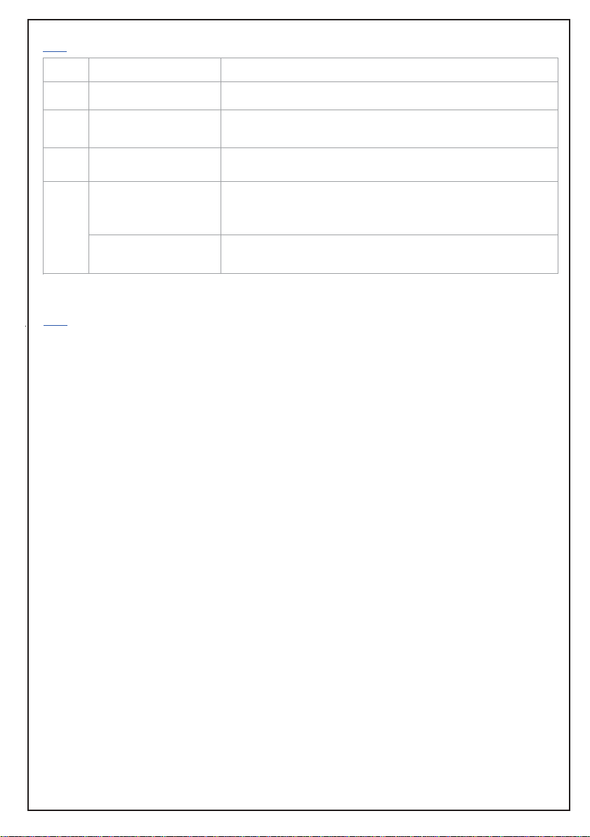
Changing the default settings of MPPT charge controller
Note: Before changing the default settings values of the device, ensure the maximum ampere and voltage
ratings applicable for your battery type and brand (SMF, LEAD-ACID, GEL) This device is not designed for
direct charging of lithium Phosphate battery . Blind settings may cause severe damage to the batteries and
charge controller. Default values given are for lead acid C10 grade solar batteries.To reset to default settings
enter settings menu 14 F-RST and set the value to "1".(Refer user manual function settings page)
Refer battery user manual for recommended charging ampere and voltage for the connected batteries.
Never try to change the default settings of the device without the help of technical advice. Note down the default
settings of the device before changing. Read function settings page before changing default settings of the
device.
Entering setup mode of MPPT charge controller.
Connect the charge controller to the desired battery bank. Consecutive pressing of the ENTER button ( )
displays the existing function settings of the charger.
To enter Setup mode , keep pressing DOWN arrow button ( ) for 3 seconds & press ENTER button ( )
also without releasing DOWN arrow button ( ) for 3 seconds. Now MPPT enters setup mode , displaying
version number and model name. Press the ENTER button ( ) to scroll through the various setup menu as
shown in the function settings page.Use the UP button ( ) to increase and DOWN button ( ) to decrease the
default values. When kept idle for 5 seconds or gone through all settings menu new settings will be saved and
the device goes to normal mode.
When default settings is changed MPPT will be in Auto bypass OFF mode. To turn ON the Auto bypass mode
press and hold UP button ( ) for 2 seconds.
Before starting it is better to make a plan of your solar energy needs and ensure your existing inverter and
batteries are suitable for solar application. When a battery is charged with limited charging ampere (6AMP to
10AMP ) for long hours it delivers good energy backup. Solar charging and discharging is a daily process with
high current from solar panels. We get only 4 to 5 hours average sun light in a day and have to charge the
batteries in this time. C10 grade solar batteries above 100 Ah have the capacity to handle high current charging
and discharging. Usually inverter batteries are either C20 grade or C10 grade normal batteries. An inverter
battery is always connected to grid power and continuously charging the batteries in limited ampere for
longhours (6AMP to 10AMP) and gives good back up. That is why we don't get enough backup from normal
batteries when charged from solar power with high current. If we use normal batteries for solar charging with
limited charging current they can't be gotfully charged before evening. So always insist on C10 grade solar
batteries for solar applications. Now check your home inverter is provided with a grid charging ON/OFF switch.
Most of the branded normal type inverters are not provided with a grid charging ON/OFF switch on them.When
we use this type of normal inverter in solar o-grid system it will charge batteries from grid power and we do
not get actual solar benefit.
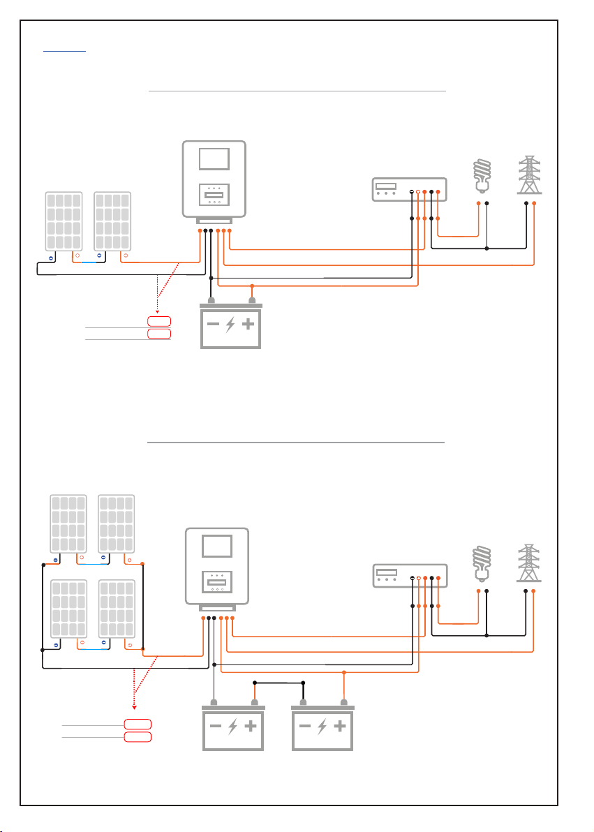
HOW THE CHARGE CONTROLLER DRIVES THE CONNECTED INVERTER
Most of the SMU type solar MPPT charge controllers are provided with an inbuilt relay to control grid power
to the inverter.Remove grid power phase wire from your inverter and connect to PHASE IN terminal of
MPPT.Connect a wire from the PHASE OUT terminal of MPPT to the PHASE IN terminal of the inverter. (Never
connect the neutral wire of grid power to any connectors of MPPT). When charging starts terminal volt of the
battery rises to the preset voltage 14.2 V (this value is adjustable) MPPT disconnects the AC mains to the
inverter and the connected load on the inverter works on battery power (solar power). when the battery
terminal volt goes down (in the evening or cloudy sky) and reaches 11.5 V (this value is adjustable) MPPT
reconnect grid power to the inverter. If your inverter is a normal type without a grid charging disabling switch
it will charge the batteries and we don't get the solar benefit. To overcome this it is better to limit the load on
the inverter and keep the battery terminal volt always high. Some customers use solar power only in the
daytime and shift the load to AC mains by keeping the shifting to AC mains voltage 12.0 V or more. Fitting an
external grid change over the relay system for bypassing grid power directly to load is also applicable. If we
use an inverter with a grid charging ON/OFF switch we can keep the switch in o position to avoid charging
from the grid. Only on cloudy days we can keep the switch in on position and charge the batteries from grid
power.
CONVERTING A NORMAL INVERTER TO A SMART SOLAR INVERTER
USING MPPT CHARGE CONTROLLER
9

MENU TYPE
DESCRIPTION RANGE
1.FLOAT-V
Battery float
charging limit
SETTINGS 13.0V 14.2V 15.5V
13.5V 14.8V 16.5V
14.0V 15.5V 16.5V
9.0V 10.5V 13.0V
"0"
day
"0"
day
180
day
3A 40A 40A
12.0V 14.2V 16.0V
MIN MAXDEFAULT
SETTINGS
SETTINGS
SETTINGS
Battery equalization
charging settings
2.BULK-V
Battery bulk
charging limit
3.EQLZ-V
Battery equalization upper
volt limit
4.BVLC-V
Battery equalization lower
volt limit
5.N-DAYS
Select the equalization in
days period
6.MAX - AMP
Set the output ampere of
MPPT
7.GRD-SOL
Set grid power to
solar shifting voltage
Limit the float charging voltage recommended for the batteries. This
value varies in dierent types of batteries. Default value given is for C10
grade solar lead acid batteries. For SMF and Gel batteries this value is
between 13.0V to 13.8V. Refer battery user manual to change the value
Limit the maximum bulk charging voltage are commended for the
batteries.This value varies in dierent types of batteries.Default value
given is for C10 grade solar Lead acid batteriesF.or SMF and Gel
batteries this value is between 13.5V to 14.5V (Refer battery user manual
before changing
(Never try to equalise sealed (SMF,SLA,GEL) batteries). Limit the
maximum voltage required to boost the lead acid batteries. Equalization
is an over charging of battery above their recommended bulk charging
voltage to equalise terminal volt of all cells. (Read page No 8)
If grid power is connected to inverter through MPPT to shift the load
automatically from grid power to battery power (solar power) set the
change over battery voltage preferred.
Limit the charging current to the battery if needed. (maximum charging
current is recommended as 20% of the Ah of a single 12V lead acid battery.
Eg: for a 150Ah battery, 30ampereis the maximum charging current
recommended. Refer battery user manual before changing the value.
Select the battery low volt level to activate auto equalization based on
battery volt.(Select a volt limit just below the inverter low volt cuto level
to control frequent equalization)
Select the number of days to activate periodic equalization
NEVER TRY TO CHANGE THE DEFAULT SETTINGS OF
THE DEVICE WITHOUT TECHNICAL ADVICE TO AVOID
MALFUNCTION AND HAZARDOUS RESULT
CAUTION
MPPT FUNCTION SETTINGS VERS.7
10

MENU TYPE
DESCRIPTION RANGE
8.SOL-GRID
Set solar power to grid
power shifting voltage
SETTINGS
9.0V 11.5V 16.0V
LB 11.7V 16.0V
10Ah 150Ah 200Ah
90 98 110
- - -
-"0"
ZERO
"0"
ZERO
"0"
ZERO
"1"
ONE
-
MIN MAXDEFAULT
SETTINGS
SETTINGS
CALIBRATION
CALIBRATION
SETTINGS
SETTINGS
9.BLK-LED
Battery low volt warning
limit
10.BAT-AH
Set the Ah of the connected
ba ttery
11.CAL-AMP
Ampere calibration settings
of MPPT
12.CAL-VOLT
Volt calibration settings
of MPPT
13.AMP-LT
Settings for initial limited
ampere charging
Initial Charging ampere is
limited to 20% of the
Ah of the connected battery
14.F-RST
Factory Reset
Set the changeover battery voltage preferred to change the load
automatically from solar power (battery power) to grid power
Blinking of blue LED indicates low battery volt. Set this value above the
vale given in the 8th menu SOL-GRID changeover
Set the Ah of the connected battery bank to limit the bulk charging
time Eg:if 2 150Ah battery is connected in series set the value 150Ah
and if connected in parallel set as 300Ah.
Note the battery volt reading on the MPPT display.Measure
batteryterminal volt using a true RMS DC voltmeter.If there is dierence
inreading UP or DOWN the default value till both readings are equal.
To reset all settings to default settings
A) Select option "0" to stop all initial limited ampere batterycharging
B) Select option "1" to start initial limited ampere charging upto the
set value of 7 the menu.(Grid to solar shifting volt)
C) Select option "2" to start initial limited amp charging up tothe setvalue
of 2nd menu. (Bulk charging)MPPT continuouson limited ampcharging
till the end of bulk charging
When MPPT charging is going on connect a true RMS DC clamp
meter(Fluke brand is better ) over the positive battery wire and ensure
the same reading is seen on the MPPT display.Calibrate and correct if
there is dierence.If the reading is less in clamp meter increase 2 or
3points using UP button and save changes.If the reading is high in the
clamp meter decrease 2 or 3 points and save the changes.the Repeat
the charging process till both display shows same reading
NEVER TRY TO CHANGE THE DEFAULT SETTINGS OF
THE DEVICE WITHOUT TECHNICAL ADVICE TO AVOID
MALFUNCTION AND HAZARDOUS RESULT
CAUTION
MPPT FUNCTION SETTINGS VERS.7
11

IMPORTANT SAFETY PRECAUTIONS
Lead Acid Batteries Produce Hydrogen Gas Which is Highly Flammable
1) Never use a flame or any kind of spark producing device near fully charged batteries as it may cause
an explosion of the batteries and fire hazard (eg: Checking battery water level under a candle flame,
spark from metal cutter or spark from loose contact of battery connecting wires )
2) Maintenance of the batteries and pv panel array at regular intervals make the solar power system
trouble free and fresh
3) Solar panels should be grouped in such a way that the maximum Open Circuit Voltage (Voc) of the
panels connected in series should not exceed the Maximum PV panel voltage recommended for each
Battery Banks.
4) Safety precautions must be taken while grouping and connecting PV panels to the charge controller
with high Voc input. (500 Volt DC current from the PV panel is highly dangerous. Never touch the
terminals without safety glows)
5) Extreme care should be taken while connecting High voltage solar power systems.
6) Earthing and wiring of high power solar system must be done under the supervision of a qualified
electrical engineer
7) Never connect the PV panel connection to the battery input or the connection of the batteries to the
PV input.
8) Never connect any of the grid line to any of the DC (PV or Battery) connection terminals.
9) The installation and use must comply with the local safety instructions and standards in force.
10) We disclaim all responsibility and liability for damage, costs or losses resulting from an installation
that does not comply with the instructions, a faulty operation or inadequate maintenance.
11) The use of the charger is in any case under the responsibility of the customer.
12) This equipment is neither designed nor guaranteed to installations used for vital medical care nor any
other critical installation entailing potential risks of damage to people or to the environment
16/404-H Ashapower Tower, Kondotty-Areekode Main Road,
Kizhisseri, Kuzhimanna PO, Malappuram
DIST,Kerala-673641,
INDIA.
Support :+91 7594 82 1003
www.ashapower.in
I N N OV ATING TOMORROW
12
Table of contents
Other ASHAPOWER Inverter manuals
Popular Inverter manuals by other brands

Santerno
Santerno Sinus Penta Assembly instructions

IFR
IFR 2026 operating manual

Hitachi
Hitachi AN072803-1 Application note

Fuji Electric
Fuji Electric Frenic Mega Series user manual

Champion Global Power Equipment
Champion Global Power Equipment 200987 Operator's manual

ComSonics
ComSonics QAM Marker user guide