2
DANGER
Before installation, read the following instructions carefully.
Failure to follow instruction and safety information could
cause serious bodily injury, death and/or property damage.
Each Ashland Pump is individually factory tested to ensure
proper performance. Closely following these instructions
will eliminate potential operating problems assuring years
of trouble-free service.
Most accidents can be avoided by using common sense.
IMPORTANT - Ashland Pump is not responsible for
losses, injury or death resulting from failure to observe
these safety precautions, misuse, abuse or misapplica-
tion of pumps or equipment.
All returned products must
be cleaned, sanitized, or
decontaminated prior to shipment, to
insure employees will not be exposed to
health hazards in handling said materials.
All applicable laws and regulations shall apply.
Bronze/brass fitted pumps may
contain lead levels higher than
considered safe for potable water systems. Government
agencies have determined that leaded copper alloys
should not be used in potable water applications.
Installation, wiring, and junction
connections must be in accord-
ance with the National Electric Code and all applicable
state and local codes. Requirements may vary depend-
ing on usage and location.
Installation and servicing is to be
conductedbyqualiedpersonnelonly.
Rotating machinery, amputation
or severe lacerations can result.
Keep clear of suction and discharge
openings. DO NOT insert fingers into
pump with power connected.
Always wear eye protection when
working on pumps. Do not wear loose clothing that
may become entangled in moving parts.
Pumps build up heat and
pressure during operation.
Allow time for pumps to cool before handling
or servicing.
Hazardous Voltage can shock,
burn or cause death. This pump is
not intended for use in swimming pools or
water installations where human contact with
pumped fluid is possible.
Risk of electrical shock. To
reduce risk of electrical shock,
always disconnect pump from source
before handling. Lock out power & tag.
WARNING
Do Not use these pumps in water
over 145°F. Do not exceed manu-
factures recommended maximum performance, as this
could cause the motor to overheat.
WARNING
WARNING
WARNING
WARNING
DANGER
DANGER
DANGER
These pumps are NOT to be
installed in locations classified
as hazardous in accordance with the
National Electric Code, ANSI/NFPA 70.
WARNING
Pumps often handle materials which
could cause illness or disease. Wear
adequate protective clothing when working on a used
pump or piping. Never enter a basin after it has been
used.
WARNING
Do not introduce into any sewer,
either directly, or through a kitchen
waste disposal unit or toilet: Seafood Shells, Aquarium
Gravel, Cat Litter, Plastic Objects, Sanitary Napkins or
Tampons, Diapers, Rags, Disposable Wipes or Cloth,
Medications, Flammable Material, Oil or Grease, Strong
Chemicals, Gasoline.
DANGER
DANGER
Do not lift, carry or hang pump by
the electrical cables. Damage to
the electrical cables can cause shock, burns or
death. Never handle connected power cords with wet
hands. Use appropriate lifting device.
DANGER
Failure to permanently ground the
pump, motor and controls before
connecting to power can cause shock, burns
or death.
DANGER
Make sure lifting handles are securely
fastened each time before lifting.
CAUTION
• Operation against a closed discharge valve will cause
premature bearing and seal failure on any pump.
• Any wiring of pumps should be performed by a
qualiedelectrician.
• Cable should be protected at all times to avoid
punctures, cuts, bruises, and abrasions-inspect
frequently.
• Never handle connected power cords with wet hands.
• Never let cords or plugs lie in water outside the sump
pit.
• These pumps are offered in a three phase and single
phasewiringconguration.Voltageswillvary
according to the application and can be seen in the
tables in this manual.
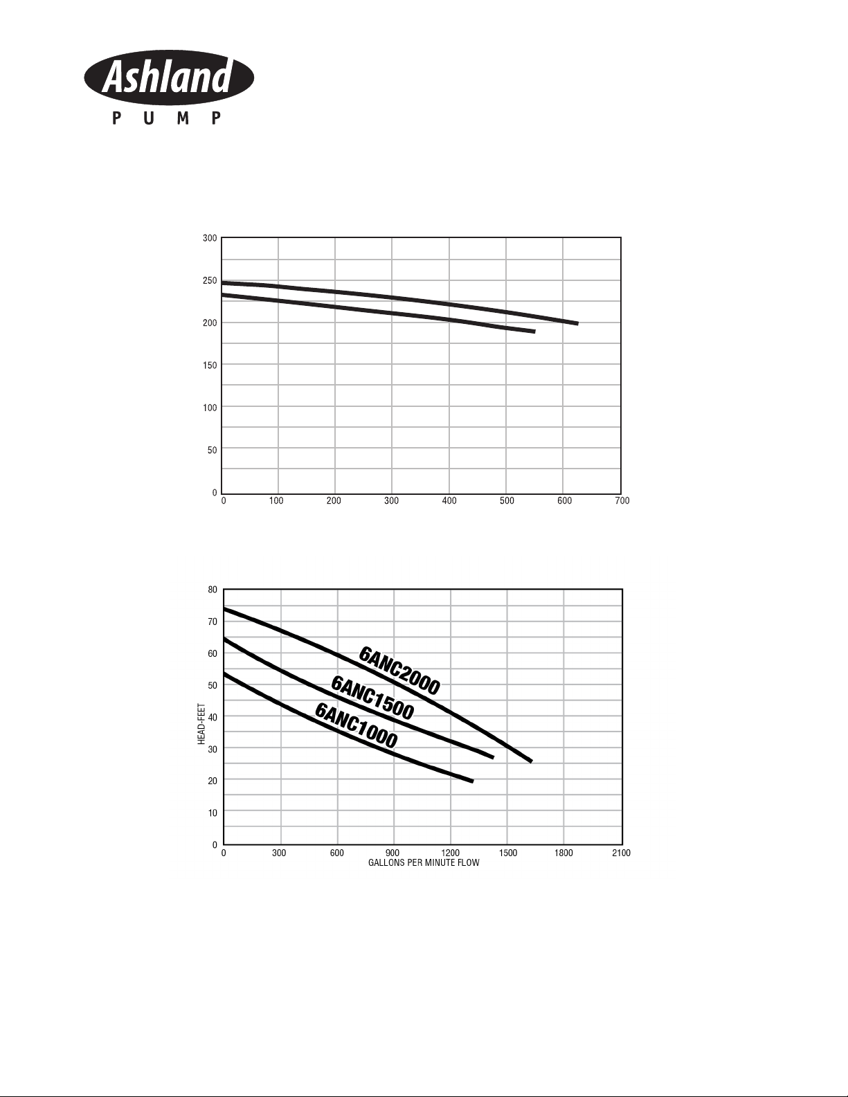
Solids Handling Pumps
Models: 3ANC300/500/750,
4ANC2500/3000/4000/5000/6000,
6ANC1000/1500/2000/3000/4000/5000/6000,
8ANC5000/6000 General Safety Information