Ashley AP5710 Operation and maintenance manual

* All Pictures In This Manual Are For Illustrative Purposes Only. Actual Product May Vary.
© 2021 United States Stove Company, 227 Industrial Park Rd., South Pittsburg, TN 37380 Ph. 800-750-2723
THIS MANUAL IS SUBJECT TO CHANGE WITHOUT NOTICE.
Owner’s Instruction and Operation Manual
U.S. Environmental Protection Agency
Certied to comply with 2020 particulate
emissions standards.
SAFETY NOTICE: If this heater is not properly installed, a house re may result.
For your safety, follow the installation instructions. Never use make-shift
compromises during the installation of this heater. Contact local building or
re ofcials about permits, restrictions and installation requirements in your
area. NEVER OPERATE THIS PRODUCT WHILE UNATTENDED.
CAUTION! Please read this entire manual before you install or use your new room
heater. Failure to follow instructions may result in property damage, bodily injury,
or even death. Improper Installation Will Void Your Warranty!
Save These Instructions In A Safe Place For Future Reference.
CALIFORNIA PROPOSITION 65 WARNING:
This product can expose you to chemicals including carbon
monoxide, which is known to the State of California to cause
cancer, birth defects, and/or other reproductive harm. For
more information, go to www.P65warnings.ca.gov
AP5710
R
Report Number: F19-549
Certied to ASTM E1509-12 (2017)
and Certied to ULC-S627-00-REV1
Mobile Home Approved
Model Number:
852523J-2302K

-2-
© 2021 United States Stove Company
INTRODUCTION
Your pellet stove has been approved for installation in the USA and Canada. It may also be installed in a
manufactured or mobile home. Your stove is Certied to ASTM E1509-12 (2017)and Certied to ULC S627-
00. This manual describes the installation and operation of the U.S. Stove, 5710-XH wood heater. This heater
meets the 2020 U.S. Environmental Protection Agency’s crib wood emission limits for wood heaters sold after
May 15, 2020. Under specic test conditions this heater has been shown to deliver heat at rates ranging from
13,281 to 27,492 Btu/hr. This heater achieved a particulate emissions rate of 1.0 g/hr when tested to method
ASTM E2779-10 (*and an efciency of 69%).
WARNING:
IT IS AGAINST FEDERAL REGULATIONS TO OPERATE THIS WOOD HEATER IN A MANNER INCONSISTENT
WITH THE OPERATING INSTRUCTIONS IN THE OWNER’S MANUAL.
Heating Specications
Fuel Burn Rate* (lowest setting) 1.5 lbs./hr. (0.7 kg/hr) * Pellet size may effect the actual rate of fuel
feed and burn times. Fuel feed rates may vary
by as much as 20%. Use PFI listed fuel for best
results.
Burn Time (lowest setting) 33 hrs. (approximate)
Hopper Capacity 50 lbs. (22.7 kg)
Flue Size 3” or 4”
Electrical Specications
Electrical Rating 110-120 Volts AC, 60 HZ, 3.0 Amps
Watts (operational) 125
Watts (igniter running) 310
Dimensions
Overall: Height x Width X Depth 32-3/16” (819 mm) x 19” (482 mm) x 23” (585 mm)
For Customer Service, please
call:
1-800-750-2723 Ext 5050 or;
Text to 423-301-5624 or;
Email us at:
customerservice@usstove.
com
Note: Register your product online at
www.usstove.com or download the
free app today. This app is available
only on the App Store for iPhone
and iPad. Search US Stove. Save your
receipt with your records for any
claims.

-3- © 2021 United States Stove Company
INSTALLATION CHECKLIST
Your Wood Stove should be installed by a qualied installer only. An NFI qualied Installer can be found at
www.ncertied.org/public/nd-an-n-pro/
CUSTOMER SERVICE
1-800-750-2723 ext 5050
Text to 423-301-5624
Email to: Customerservice@usstove.com
COMMISSIONING CHECKLIST
This Checklist is to be completed in full by the qualied person who installs this unit. Keep this page for future
reference.
Failure to install and commission according to the manufacturer’s instructions and complete this checklist
will invalidate the warranty.
Please Print
Customer Name: Telephone Number:
Address:
Model:
Serial Number:
Installation Company Name: Phone Number:
Installation Technician’s Name: License Number:
DESCRIPTION OF WORK
Location of installed appliance: _________________________________________________________________________
Venting System: New Venting System Yes No If yes, Brand __________________________________
If no, Date of inspection of existing venting system:______________________________________________________
COMMISSIONING
Conrm Hearth Pad Installation as per Installation Instructions............................................................................................
Conrm proper placement of internal parts ........................................................................................................................................
Check soundness of door gasket and door seals...............................................................................................................................
Conrm clearances to combustibles as per installation instructions in this manual ................................................
Check the operations of the air controls .................................................................................................................................................
Conrm the venting system is secure and sealed ............................................................................................................................
Conrm the stove starts and operates properly.................................................................................................................................
Check to ensure a CO alarm is installed as per local building codes and is functional ............................................
Explain the safe operation, proper fuel usage, cleaning, and routine maintenance requirements .................
Declaration of Completion: As the qualied person responsible for the work described above, I conrm that
the appliance as associated work has been installed as per manufacturer’s instructions and following any
applicable building and installation codes.
Signed: ___________________________________Print Name: ______________________________ Date: _____________
Home Owner: RETAIN THIS INFORMATION FOR FUTURE REFERENCE

-4-
© 2021 United States Stove Company
ASSEMBLY INSTRUCTIONS
FOR CUSTOMER SERVICE CALL: 800-750-2723 EXT 5050
1. Pull the factory installed wires out of the top of
the stove. There will be two wire harnesses, as
shown.
2. Unpack the top mount controls and ensure that
the wiring harness shown is attached securely.
3. Connect the factory installed wiring harnesses to
the control panel as shown.
4. Secure the control panel to the top of the stove
with two sheet metal screws.

-5- © 2021 United States Stove Company
INSTALLATION
SAFETY NOTICE
• IF THIS STOVE IS NOT PROPERLY INSTALLED,
A HOUSE FIRE MAY RESULT. TO REDUCE THE
RISK OF FIRE, FOLLOW THE INSTALLATION
INSTRUCTIONS.
• CONTACTYOURLOCALBUILDING OFFICIALSTO
OBTAIN A PERMIT AND INFORMATION ON ANY
ADDITIONAL INSTALLATION RESTRICTIONS OR
INSPECTION REQUIREMENTS IN YOUR AREA.
• DO NOT PLACE CLOTHING OR OTHER
FLAMMABLE ITEMS ON OR NEAR THIS STOVE.
• NEVER USE GASOLINE, GASOLINE-TYPE
LANTERN FUEL, KEROSENE, CHARCOAL
LIGHTER FLUID, OR SIMILAR LIQUIDS TO START
OR ’FRESHEN UP’ A FIRE IN THIS STOVE. KEEP
ALL SUCH LIQUIDS WELL AWAY FROM THE
STOVE WHILE IT IS IN USE.
• THIS APPLIANCE IS A FREESTANDING HEATER.
IT IS NOT INTENDED TO BE ATTACHED TO ANY
TYPEOFDUCTING.ITISNOTAFURNACE.DONOT
CONNECT THISUNITTOANYAIR DISTRIBUTION
DUCT OR SYSTEM. THIS APPLIANCE IS NOT
INTENDED FOR COMMERCIAL USE.
• INSTALL VENT AT CLEARANCES SPECIFIED BY
THE VENT MANUFACTURER.
• DO NOT INSTALL A FLUE DAMPER IN THE
EXHAUST VENTING SYSTEM OF THIS UNIT.
• YOUR STOVE REQUIRES PERIODIC
MAINTENANCE AND CLEANING (SEE
”MAINTENANCE”). FAILURE TO MAINTAIN
YOUR STOVE MAY LEAD TO IMPROPER AND/OR
UNSAFE OPERATION.
• A POWER SURGE PROTECTOR IS REQUIRED.
THIS UNIT MUST BE PLUGGED INTO A 110 -
120V, 60 HZ GROUNDED ELECTRICAL OUTLET.
DO NOT USE AN ADAPTER PLUG OR SEVER
THE GROUNDING PLUG. DO NOT ROUTE THE
ELECTRICAL CORD UNDERNEATH, IN FRONT
OF, OR OVER THE HEATER. DO NOT ROUTE THE
CORD IN FOOT TRAFFIC AREAS OR PINCH THE
CORD UNDER FURNITURE.
CAUTION:
BURNING FUEL CREATES CARBON MONOXIDE
AND CAN BE HAZARDOUS TO YOUR HEALTH IF
NOT PROPERLY VENTED.
ATTENTION:
• A WORKING SMOKE DETECTOR MUST BE
INSTALLED IN THE SAME ROOM AS THIS
PRODUCT.
• INSTALL A SMOKE DETECTOR ON EACH FLOOR
OF YOUR HOME; INCASE OF ACCIDENTAL FIRE
FROM ANY CAUSE IT CAN PROVIDE TIME FOR
ESCAPE.
• THESMOKEDETECTORMUSTBEINSTALLEDAT
LEAST 15 FEET (4,57 M) FROM THE APPLIANCE
IN ORDER TO PREVENT UNDUE TRIGGERING OF
THE DETECTOR WHEN RELOADING.
CAUTION:
• USE OF OUTSIDE AIR IS NOT REQUIRED FOR
THIS UNIT.
• DO NOT UNPLUG THE STOVE IF YOU SUSPECT
A MALFUNCTION. TURN THE ON/OFF SWITCH
TO ”OFF’ AND CONTACT CUSTOMER SERVICE.
• THE HEATER WILL NOT OPERATE DURING A
POWER OUTAGE. IF A POWER OUTAGE DOES
OCCUR, CHECK THE HEATER FOR SMOKE
SPILLAGE AND OPEN A WINDOW IF ANY
SMOKE SPILLS INTO THE ROOM.
• NEVER BLOCK FREE AIRFLOW THROUGH THE
OPEN VENTS OF THE UNIT.
US Stove highly recommends your stove be installed by a
qualified NFI (US) or WETT (Canada) technician. To find
the nearest qualified installer, go to:
https://nficertified.org,
https://www.wettinc.ca/

-6-
© 2021 United States Stove Company
INSTALLATION
IMPROPER INSTALLATION
The use of other components other than stated
herein could cause bodily harm, heater damage, and
void your warranty. The manufacturer will not be held
responsible for damage caused by the malfunction
of a stove due to improper venting or installation.
FLOOR PROTECTION
This heater must have a non-combustible oor
protector (UL1618 ember protection) installed
beneath it if the oor is of combustible material.
US - Floor protector should be UL listed or equal too,
needs to extend 6” to the front, 6” to each side, 1” to
the rear of the unit. Under and 2” beyond each side
of the cleanout tee if an interior vertical installation.
Canada - Floor protector should comply with CAN/
ULC standards. Needs to extend 18” to the front, 8”
beyond each side of the unit.
A Back to Stove U.S.A 1” 26 mm
CAN 8” 204 mm
BSide to Stove U.S.A 6” 153 mm
CAN 8” 204 mm
C Front to Stove U.S.A 6” 153 mm
CAN 8” 204 mm
DBack to Flue 2” 51 mm
CLEARANCES
Your pellet stove has been tested and listed for
installation in residential, mobile home in accordance
with the clearances given below. For safety reasons,
please adhere to the installation clearances
and restrictions. Any reduction in clearance to
combustibles may only be done by means approved
by a regulatory authority.
ESide Wall to Stove 10” 245 mm
FSide Wall to Vent Pipe 11-1/2” 292 mm
GBack Wall to Stove 11-7/8” 302 mm
H Back Wall to Vent Pipe 3” 76 mm
JCeiling to Floor 84” 2134 mm
KCeiling to Stove 53-7/8’ 1434 mm
LSide Wall to Stove 7-1/2” 191 mm
M Side Wall to Vent Pipe 11-1/4” 286 mm
NBack Wall to Vent Pipe 7-1/2” 191 mm
FOR CUSTOMER SERVICE CALL: 800-750-2723 EXT 5050

-7- © 2021 United States Stove Company
OUTSIDE AIR SUPPLY (OPTIONAL, UNLESS
INSTALLING IN A MOBILE HOME)
Depending on your location and home construction,
outside air may be necessary for optimal
performance. Your stove is approved to be installed
with an outside air intake (69FAK) which is necessary
for a mobile home. You can purchase the 69FAK
through your heater dealer. Installation instructions
are supplied with the air intake kit.
ATTENTION:
DO NOT VENT UNDER ANY PORCH, DECK,
AWNING, OR IN ANY SEMI ENCLOSED OR
ROOFED AREA. DOING SO MAY RESULT IN
UNPREDICTABLE AIRFLOW AT THE VENT CAP
UNDER CERTAIN CONDITIONS AND CAN AFFECT
THE PERFORMANCE OF YOUR STOVE, AS WELL
AS, OTHER UNFORESEEABLE ISSUES.
SECURING APPLIANCE TO THE FLOOR
Use the designated holes to secure the unit to the
oor.
Fresh Air
Intake
Exhaust
Pipe
WARNING! DO NOT INSTALL IN SLEEPING ROOM.
CAUTION! THE STRUCTURAL INTEGRITY OF THE
MOBILE HOME FLOOR, WALL, AND CEILING/ROOF
MUST BE MAINTAINED.
WHEN INSTALLED IN A MOBILE HOME, THE STOVE
MUST BE GROUNDED DIRECTLY TO THE STEEL
CHASSIS AND BOLTED TO THE FLOOR.
In addition to the previously detailed installation
requirements, mobile home installations must meet
the following requirements:
• This stove must be securely fastened to the oor
of the mobile home through the two holes in the
rear of the stove using 2, 1/4” lag bolts that are long
enough to go through both a hearth pad, if used,
and the oor of the home.
• The heater must be electrically grounded to the
steel chassis of the mobile home with 8 GA copper
wire using a serrated or star washer to penetrate
paint or protective coating to ensure grounding.
• Vent must be 3 or 4-inch “PL” Vent and must extend
a minimum or 36” (914 mm) above the roof line of
the mobile home and must be installed using a
certied ceiling re stop and rain cap.
• When moving your mobile home, all exterior
venting must be removed while the mobile home
is being relocated. After relocation, all venting
must be reinstalled and securely fastened.
• Outside Air is mandatory for mobile home
installation. See Outside Air Supply section and
your dealer for purchasing.
• Check with your local building ofcials as other
codes may apply.
VENTING REQUIREMENTS
WARNING:
• INSTALL VENT AT CLEARANCES SPECIFIED BY
THE VENT MANUFACTURER.
• DO NOT CONNECT THE PELLET VENT TO A VENT
SERVING ANY OTHER APPLIANCE OR STOVE.
• DO NOT INSTALL A FLUE DAMPER IN THE
EXHAUST VENTING SYSTEM OF THIS UNIT.
The following installation guidelines must be
followed to ensure conformity with both the safety
listing of this stove and to local building codes. Do
not use makeshift methods or compromise in the
installation.
IMPORTANT:
THIS UNIT IS EQUIPPED WITH A NEGATIVE DRAFT
SYSTEM THAT PULLS AIR THROUGH THE BURN
POT AND PUSHES THE EXHAUST OUT OF THE
DWELLING. IF THIS UNIT IS CONNECTED TO A FLUE
SYSTEM OTHER THAN THE WAY EXPLAINED IN
THIS MANUAL, IT WILL NOT FUNCTION PROPERLY.
MAXIMUM VENTING DISTANCE
Installation MUST include at least 3-feet of vertical
pipe outside the home. This will create some natural
draft to reduce the possibility of smoke or odor during
appliance shutdown and keep exhaust from causing
a nuisance or hazard by exposing people or shrubs
to high temperatures. The maximum recommend
vertical venting height is 12-feet for 3-inch type “PL”
vent. Total length of horizontal
INSTALLATION

-8-
© 2021 United States Stove Company
vent must not exceed 4-feet. This could cause back
pressure. Use no more than 180 degrees of elbows
(two 90-degree elbows, or two 45-degree and one
90-degree elbow, etc.) to maintain adequate draft.
IMPORTANCE OF PROPER DRAFT
Draft is the force which moves air from the appliance
up through the chimney. The amount of draft in your
chimney depends on the length of the chimney, local
geography, nearby obstructions and other factors.
Too much draft may cause excessive temperatures
in the appliance. Inadequate draft may cause
backpufng into the room and ‘plugging’ of the
chimney. Inadequate draft will cause the appliance
to leak smoke into the room through appliance and
chimney connector joints. An uncontrollable burn
or excessive temperature indicates excessive draft.
Take into account the chimney’s location to ensure
it is not too close to neighbours or in a valley which
may cause unhealthy or nuisance conditions.
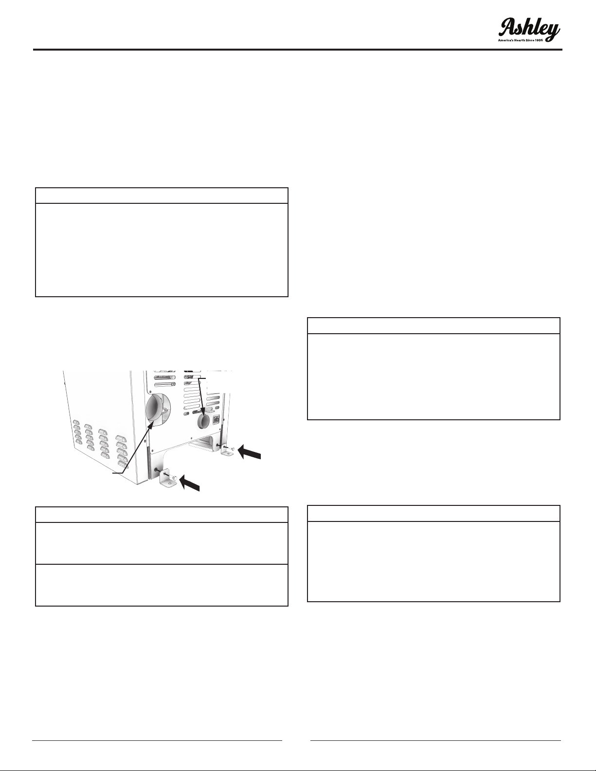
PELLET VENT TYPE
A certied 3-inch or 4-inch type “PL” pellet vent
exhaust system must be used for installation and
attached to the pipe connector provided on the
back of the stove (use a 3-inch to 4-inch adapter for
4-inch pipe). Connection at back of stove must be
sealed using Hi-Temp RTV. Use 4-inch vent if the
vent height is over 12-feet or if the installation is over
2,500 feet above sea level. We recommend the use of
Simpson Dura-Vent® or Metal-Fab® pipe (if you use
other pipe, consult your local building codes and/
or building inspectors). Do not use Type-B Gas Vent
pipe or galvanized pipe with this unit. The pellet vent
pipe is designed to disassemble for cleaning and
should be checked several times during the burning
season. Pellet vent pipe is not furnished with the unit
and must be purchased separately.
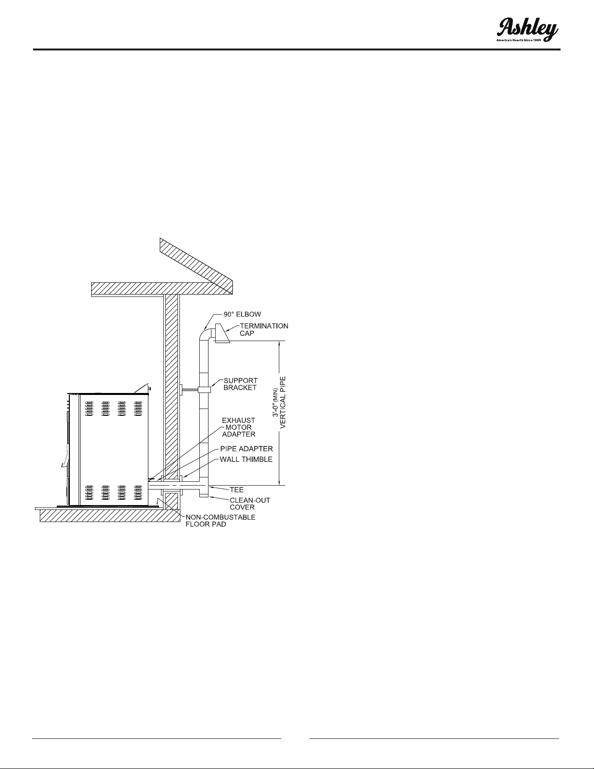
PELLET VENT INSTALLATION
The installation must include a clean-out tee to
enable collection of y ash and to permit periodic
cleaning of the exhaust system. 90-degree elbows
accumulate y ash and soot thereby reducing
exhaust ow and performance of the stove. Each
elbow or tee reduces draft potential by 30% to 50%.
All joints in the vent system must be fastened by
at least 3 screws, and all joints must be sealed with
Hi-Temp RTV silicone sealant to be airtight. The
area where the vent pipe penetrates to the exterior
of the home must be sealed with silicone or other
means to maintain the vapor barrier between the
exterior and the interior of the home. Vent surfaces
can get hot enough to cause burns if touched by
children. Noncombustible shielding or guards may
be required.
PELLET VENT TERMINATION
Do not terminate the vent in an enclosed or semi-
enclosed area, such as; carport, garage, attic, crawl
space, under a sun deck or porch, narrow walkway, or
any other location that can build up a concentration
of fumes. Termination in one of these areas can also
lead to unpredictable pressure situations with the
appliance, and could result in improper performance
and/or malfunction. The termination must exhaust
above the outside air inlet elevation. The termination
must not be located where it will become plugged
by snow or other materials. Do not terminate the
venting into an existing steel or masonry chimney.
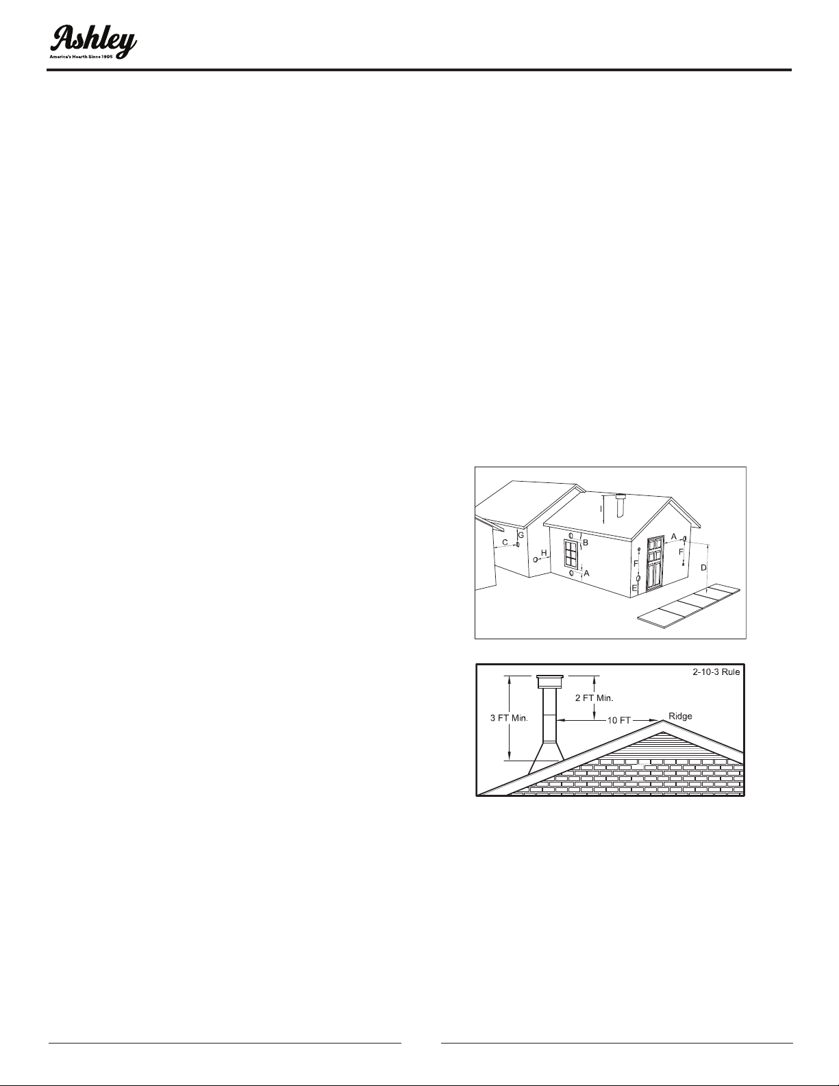
VENT TERMINATION CLEARANCES
A. Minimum 4-foot (1.22m) clearance below or
beside any door or window that opens.
B. Minimum 1-foot (0.3m) clearance above any door
or window that opens.
C. Minimum 3-foot (0.91m) clearance from any
adjacent building.
D. Minimum 7-foot (2.13m) clearance from any
grade when adjacent to public walkways.
E. Minimum 2-foot (0.61m) clearance above any
grass, plants, or other combustible materials.
INSTALLATION

-9- © 2021 United States Stove Company
A. Minimum 3-foot (0.91m) clearance from an forced
air intake of any appliance.
B. Minimum 2-foot (0.61m) clearance below eves or
overhang.
C. Minimum 1-foot (0.3m) clearance horizontally
from combustible wall.
D. Must be a minimum of 3 foot (0.91m) above the
roof and 2 foot (0.61m) above the highest point or
the roof within 10 feet (3.05m).
THROUGH THE WALL INSTALLATION
(RECOMMENDED INSTALLATION)
TYPICAL THROUGH THE
WALL INSTALLATION
Canadian installations must conform to CAN/
CSA-B365. To vent the unit through the wall, connect
the pipe adapter to the exhaust motor adapter. If
the exhaust adapter is at least 18” (457 mm) above
ground level, a straight section of pellet vent pipe can
be used through the wall. Your heater dealer should
be able to provide you with a kit that will handle
most of this installation, which will include a wall
thimble that will allow the proper clearance through
a combustible wall. Once outside the structure, a 3”
(76 mm) clearance should be maintained from the
outside wall and a clean out tee should be placed
on the pipe with a 90-degree turn away from the
house. At this point, a 3ft (0.91m) (minimum) section
of pipe should be added with a horizontal cap, which
would complete the installation. A support bracket
should be placed just below the termination cap
or one every 4ft (1.22m) to make the system more
stable. If you live in an area that has heavy snowfall,
it is recommended that the installation be taller
than 3ft (0.91m) to get above the snowdrift line.
This same installation can be used if your heater is
below ground level by simply adding the clean-out
section and vertical pipe inside until ground level is
reached. With this installation you have to be aware
of the snowdrift line, dead grass, and leaves. We
recommend a 3ft (0.91m) minimum vertical rise on
the inside or outside of the house. The “through the
wall” installation is the least expensive and simplest
installation. Never terminate the end vent under a
deck, in an alcove, under a window, or between two
windows. We recommend Simpson Dura-Vent® or
Metal-Fab® kits.
THROUGH THE ROOF/CEILING
INSTALLATION
• When venting the heater through the ceiling, the
pipe is connected the same as through the wall,
except the clean-out tee is always on the inside
of the house, and a 3” (76 mm) adapter is added
before the clean-out tee.
• You must use the proper ceiling support anges and
roof ashing (supplied by the pipe manufacturer;
follow the pipe manufacturer’s directions). It is
important to note that if your vertical run of pipe
is more than 12ft (3.7m), the pellet vent pipe size
should be increased to 4” (102 mm) in diameter.
• Do not exceed more than 4ft (1.22m) of pipe on a
horizontal run and use as few elbows as possible. If
an offset is required, it is better to install 45-degree
elbows rather than 90-degree elbows.
INSTALLATION

-10-
© 2021 United States Stove Company
PANEL CONTROLS
The blowers and automatic fuel supply are controlled
from a panel on the top of this unit. The control panel
functions are as follows.
A. ON/OFF SWITCH (“POWER” BUTTON)
• When pushed, the stove will automatically ignite.
No other re starter is necessary. The igniter
will stay on for at least 10 and up to 12 minutes,
depending on when Proof of Fire is reached. The
re should start in approximately 5 minutes.
• The red light located above the “POWER” button
will turn green when pressed and remain green
until the stove is turned off.
• After pushing “POWER”, the auger motor is on for
3.5 minutes, off for 1 minute. During the remainder
of the start-up period, the auger motor operates
on the heat range “1” setting.
• During start up the heat level advance (Up and
Down keys) will change the heat range indicator
level accordingly, but there is no change in the
stoves operating conditions until start-up is
completed.
• During start-up ignition must occur within 12
minutes or the stove will error out and show E4.
• During the start-up phase, the Mode key does not
function.
B. LEVEL / TEMP ARROW BUTTONS
• These buttons when pushed will set the pellet feed
rate, hence the heat output or heat range of your
stove.
• The levels of heat output will incrementally change
on the bar graph starting from heat range “1” to
heat range “5”.
C. °C / °F Button
• The °C / °F button changes the two digit display
from degrees Celsius to degrees Fahrenheit.
D. MODE (M/T) BUTTON
• The Mode of the stove can be switched between
manual and controlled with a Thermostat. Separate
LEDs to the left of the two digit display indicate the
mode of operation – Manual or T-Stat. The stove
has to be in normal operation to be switched from
Manual to T-Stat mode.
• Manual mode operates according to the 5 set
levels of feed on the bar graph from heat range “1”
to heat range “5”.
T-Stat mode works as follows:
• The stove has a built in Thermostat into the controls
of the appliance. The temperature sensor for the
T-Stat is located on the back of the stove behind
the display board.
• Once the stove has gone into run mode the stove
can be switch into T-Stat mode.
• The Up and Down Level / Temp Arrow buttons are
used to change the desired set-point temperature.
Once the desired temperature is reached the two
digit display will ash for four seconds and reset to
the actual room temperature.
• Once the stove reaches within 3°F of the desired
temperature set point, it returns to the heat range
that the stove was set on before it was switched
to T-Stat mode (if the stove was running on heat
range “5” when switched to T-stat mode when it
gets within 3°F of the set point it will return to heat
range “5”).
• Once the stove reaches the desired set-point, the
stove will drop to heat range “1”.
• When room temperature drops below desired set-
point the stove will ramp back up until it reaches
the desired temperature.
HOW TO ADJUST THE FUEL ADJUSTER
It is a common occurrence in the pellet industry for
the average pellet size to vary. Due to the varying
sizes of pellets, this appliance is equipped with a fuel
adjuster to adjust the amount of fuel allowed to pass
into the auger assembly. The fuel adjuster is located
inside the hopper. Note: The factory default setting
for this is full open. To decrease the ow of pellets,
move the fuel adjuster down.
OPERATION INSTRUCTIONS
NEVER OPERATE THIS PRODUCT WHILE UNATTENDED

-11- © 2021 United States Stove Company
1. Turn off and unplug the appliance.
2. Loosen the two wing-nuts.
3. Adjust up to increase, or down to reduce the fuel
usage based on the size of the pellets.
4. Tighten the two wing-nuts.
WARNING:
• DO NOT USE CHEMICALS OR FLUIDS TO START
THE FIRE - NEVER USE GASOLINE, GASOLINE-
TYPE LANTERN FUEL, KEROSENE, CHARCOAL
LIGHTER FLUID, OR SIMILAR LIQUIDS TO START
OR “FRESHEN UP” A FIRE IN THIS STOVE. KEEP
ALL SUCH LIQUIDS WELL AWAY FROM THE
STOVE WHILE IT IS IN USE.
• HOT WHILE IN OPERATION. KEEP CHILDREN,
CLOTHING AND FURNITURE AWAY. CONTACT
MAY CAUSE SKIN BURNS.
This heater is designed to burn only PFI Premium
grade pellets. DO NOT BURN:
1. Garbage;
2. Lawn clippings or yard waste;
3. Materials containing rubber, including tires;
4. Materials containing plastic;
5. Waste petroleum products, paints or paint
thinners, or asphalt products;
6. Materials containing asbestos;
7. Construction or demolition debris;
8. Railroad ties or pressure-treated wood;
9. Manure or animal remains;
10. Salt water driftwood or other previously salt
water saturated materials;
11. Unseasoned wood; or
12. Paper products, cardboard, plywood, or
particleboard. The prohibition against burning
these materials does not prohibit the use of re
starters made from paper, cardboard, saw dust,
wax and similar substances for the purpose of
starting a re in an affected wood heater.
Burning these materials may result in release of toxic
fumes or render the heater ineffective and cause
smoke.
PROPER FUEL
ATTENTION:
THIS APPLIANCE IS DESIGNED FOR THE USE OF
PELLETIZED FUEL THAT MEET OR EXCEED THE
STANDARD SET BY THE PELLET FUEL INSTITUTE
(PFI).
Your pellet stove is designed to burn premium
hardwood pellets that comply with the Pellet Fuels
Institute (PFI) standard (minimum of 40 lbs density
per cubic ft, 1/4” to 5/16” diameter, length no greater
than 1.5”, not less than 8,200 BTU/lb, moisture under
8% by weight, ash under 1% by weight, and salt under
300 parts per million). Pellets that are soft, contain
excessive amounts of loose sawdust, have been, or
are wet, will result in reduced performance. Store your
pellets in a dry place. DO NOT store the fuel within
the installation clearances of the unit or within the
space required for refuelling and ash removal. Doing
so could result in a house re. Do not over re or use
volatile fuels or combustibles, doing so may cause a
personal and property damage hazards. THIS STOVE
IS APPROVED FOR BURNING PELLETIZED WOOD
FUEL ONLY ! Factory-approved pellets are those 1/4”
or 5/16” in diameter and not over 1” long. Longer or
thicker pellets sometimes bridge the auger ights,
which prevents proper pellet feed. Burning wood
in forms other than pellets is not permitted. It will
violate the building codes for which the stove has
been approved and will void all warranties. The
design incorporates automatic feed of the pellet
fuel into the re at a carefully prescribed rate. Any
additional fuel introduced by hand will not increase
heat output but may seriously impair the stoves
performance by generating considerable smoke.
Do not burn wet pellets. The stove’s performance
depends heavily on the quality of your pellet fuel.
Avoid pellet brands that display these characteristics:
• Excess Fines – “Fines” is a term describing crushed
pellets or loose material that looks like sawdust or
sand. Pellets can be screened before being placed
in hopper to remove most nes.
OPERATION INSTRUCTIONS

-12-
© 2021 United States Stove Company
• Binders – Some pellets are produced with materials
to hold the together, or “bind” them.
• High ash content – Poor quality pellets will often
create smoke and dirty glass. They will create a need
for more frequent maintenance. You will have to
empty the burn pot plus vacuum the entire system
more often. Poor quality pellets could damage the
auger. We cannot accept responsibility for damage
due to poor quality pellet.
CAUTION:
• KEEP FOREIGN OBJECTS OUT OF THE HOPPER.
• THE MOVING PARTS OF THIS STOVE ARE
PROPELLED BY HIGH TORQUE ELECTRIC
MOTORS. KEEP ALL BODY PARTS AWAY FROM
THE AUGER WHILE THE STOVE IS PLUGGED
INTO AN ELECTRICAL OUTLET. THESE MOVING
PARTS MAY BEGIN TO MOVE AT ANY TIME
WHILE THE STOVE IS PLUGGED IN.
PRE-START-UP CHECK
Remove burn pot, making sure it is clean and none
of the air holes are plugged. Clean the rebox, and
then reinstall burn pot. Clean door glass if necessary
(a dry cloth or paper towel is usually sufcient). Never
use abrasive cleaners on the glass or door. Check fuel
in the hopper, and rell if necessary.
BUILDING A FIRE
Never use a grate or other means of supporting the
fuel. Use only the burn pot supplied with this heater.
Hopper lid must be closed in order for the unit to
feed pellets. During the start-up period:
1. Make sure the burn pot is free of pellets.
2. DO NOT open the viewing door.
3. DO NOT add pellets to the burn pot by hand.
NOTE: During the rst few res, your stove will emit
an odor as the high-temperature paint cures or
becomes seasoned to the metal. Maintaining smaller
res will minimize this. Avoid placing items on the
stovetop during this period because the paint could
be affected. Attempts to achieve heat output rates
that exceed heater design specications can result
in permanent damage to the heater.
AUTOMATIC IGNITOR
Fill hopper and clean burn pot.
1. Press “On/Off” button. Make sure green light
comes on.
2. Adjust feed rate to desired setting by pressing
“Heat Level Advance” button.
If re doesn’t start in 12 minutes, press “On/Off”,
wait a few minutes, clear the burn pot, and start
procedure again.
DAMPER CONTROL
The damper control lever is located on the back of
the stove on the lower left side. The default setting for
the damper control should be full open. The damper
adjusts the combustion air. This control is necessary
due to the varied burn characteristics of individual
installations, different pellet brands and pellet feed
rates. It allows you to improve the efciency of your
stove. Providing correct combustion air will reduce
the frequency of cleaning your glass door and
prevent the rapid buildup of creosote inside your
stove and chimney. You should adjust the damper
based on the re’s appearance. A low, reddish, dirty
re can be improved by turning the damper slightly
to the right. A “blow torch” re can be improved by
turning the dampener to the left a little bit.
OPENING DOOR
CAUTION:
• DO NOT OPERATE YOUR STOVE WITH THE
VIEWING DOOR OPEN. THE AUGER WILL NOT
FEEDPELLETSUNDERTHESECIRCUMSTANCES
AND A SAFETY CONCERN MAY ARISE FROM
SPARKS OR FUMES ENTERING THE ROOM.
• THE FEED DOOR MUST BE CLOSED AND SEALED
DURING OPERATION.
If the door is opened while the stove is in operation
it must be closed within 30 seconds or the stove will
shut down. If the stove shuts down push the “On/
Off” button to re-start your stove. The stove will have
to fully shut down and turn off before you will be able
to restart the stove.
OPERATION INSTRUCTIONS

-13- © 2021 United States Stove Company
ROOM AIR FAN
When starting your stove the Room Air Fan will not
come on until the stove’s heat exchanger warms up.
This usually takes about 10 minutes from start-up.
IF STOVE RUNS OUT OF PELLETS
The re goes out and the auger motor and blowers
will run until the stove cools. This will take 30 minutes
or longer depending on the heat remaining in the
appliance. After the stove components stop running
all lights on the display will go out and the two digit
display will begin ashing “E3”
REFUELLING
CAUTION:
• THE HOPPER AND STOVE TOP WILL BE HOT
DURING OPERATION; THEREFORE, YOU
SHOULD ALWAYS USE SOME TYPE OF HAND
PROTECTION WHEN REFUELING YOUR STOVE.
• DO NOT TOUCH THE HOT SURFACES OF THE
STOVE. EDUCATE ALL CHILDREN ON THE
DANGERS OF A HIGH-TEMPERATURE STOVE.
YOUNG CHILDREN SHOULD BE SUPERVISED
WHEN THEY ARE IN THE SAME ROOM AS THE
STOVE.
• NEVER PLACE YOUR HAND NEAR THE AUGER
WHILE THE STOVE IS IN OPERATION.
• WE RECOMMEND YOU NOT LET THE HOPPER
DROP BELOW 1/4 FULL.
WARNING:
• KEEP HOPPER LID CLOSED AT ALL TIMES
EXCEPT WHEN REFILLING.
• DO NOT OVERFILL HOPPER.
TAMPER WARNING
This wood heater has a manufacturer-set minimum
low burn rate that must not be altered. It is against
federal regulations to alter this setting or otherwise
operate this wood heater in a manner inconsistent
with operating instructions in this manual.
SHUTDOWN PROCEDURE
WARNING:
NEVER SHUT DOWN THIS UNIT BY UNPLUGGING
IT FROM THE POWER SOURCE.
Turning your stove off is a matter of pressing the
“POWER” button on the display board. The green
light will turn back to red when the “POWER” button
is pushed. The auger motor will stop, and the blowers
will continue to operate until the internal rebox
temperatures have fallen to a preset level.
1. Your stove is equipped with a high temperature
thermodisc. This unit has a manual reset
thermodisc. This safety switch has two functions.
A. To recognize an overheat situation in the stove
and shut down the fuel feed or auger system.
B. In case of a malfunctioning convection blower, the
high-temperature thermodisc will automatically
shut down the auger, preventing the stove from
overheating.
NOTE: On some units, once tripped, like a circuit
breaker, the reset button will have to be pushed
before restarting your stove. On other units the
thermodisc has no reset button and will reset
itself once the stove has cooled. The manufacturer
recommends that you call customer service if this
occurs as this may indicate a more serious problem.
A service call may be required.
2. If the combustion blower fails, an air pressure
switch will automatically shut down the auger.
NOTE: Opening the stove door for more than
30 seconds during operation will cause enough
pressure change to activate the air switch, shutting
the fuel feed off. The stove will shut down and show
“E2” on the two digit display. The stove has to fully
shut down before restarting.
OPTIMAL OPERATION
This pellet stove has been certied by the US EPA
to meet strict 2020 guidelines. To Insure this unit
produces the optimal minimal emissions, it is critical
to follow the following guidelines.To achieve a “high
burn” your stove should be set on setting 5 with the
damper fully open.To achieve a “medium burn” your
stove should be set on setting 1 with the damper fully
closed.To achieve a “low burn” your stove should be
set on setting 1 with the damper open.Settings 2,3 &
4 will give you a higher heat output above medium
and the damper should be open for these settings.
If the door is opened while the stove is in operation
it must be closed within 30 seconds or the stove will
shut down. If the stove shuts down push the “On/
Off” button to re-start your stove. The stove will have
to fully shut down and turn off before you will be able
to restart the stove
OPERATION INSTRUCTIONS

-14-
© 2021 United States Stove Company
INTERIOR CHAMBERS
• Burn Pot - Periodically remove and clean the burn
pot and the area inside the burn pot housing. In
particular, it is advisable to clean out the holes
in the burn pot to remove any build up that may
prevent air from moving through the burn pot
freely.
• Heat Exchanger - There is a clean out plate on
both sides of the heat exchanger that need to be
removed to clean y ash out of the heat exchanger.
The cleanouts are located inside the cabinet doors,
on the lower front corners of the heat exchanger.
To access these clean outs, you must remove both
side panels. The clean outs are secured to the
rebox with (2) 5/16” screws. Remove the clean
outs and vacuum out any accumulated ash. This
should be done at least once per month or more
frequently if large amounts of ash are noticed
while cleaning or if the stove does not seem to be
burning properly.
If a vacuum is used to clean your stove, we suggest
using the AV15E AshVac vacuum. The AV15E AshVac
is designed for ash removal. Some regular vacuum
cleaner (i.e. shop vacs) may leak ash into the room.
DO NOT VACUUM HOT ASH.
WARNING:
FAILURETOPROPERLYMAINTENANCETHECLEAN
OUTS WILL RESULT IN POOR PERFORMANCE OF
THIS STOVE.
Clean-Out
Plate
Clean-Out
Plate
OPERATION INSTRUCTIONS

-15- © 2021 United States Stove Company
MAINTENANCE
CAUTION:
• FAILURE TO CLEAN AND MAINTAIN THIS
UNIT AS INDICATED CAN RESULT IN POOR
PERFORMANCE, SAFETY HAZARDS, FIRE, AND
EVEN DEATH.
• NEVER PERFORM ANY INSPECTIONS,
CLEANING, OR MAINTENANCE ON A HOT
STOVE.
• DISCONNECT THE POWER CORD BEFORE
PERFORMING ANY MAINTENANCE! NOTE:
TURNING THE ON/OFF SWITCH TO ”OFF”
DOES NOT DISCONNECT ALL POWER TO THE
ELECTRICAL COMPONENTS OF THE STOVE.
• DO NOT OPERATE STOVE WITH BROKEN GLASS,
LEAKAGE OF FLUE GAS MAY RESULT.
CREOSOTE FORMATION, INSPECTION, &
REMOVAL
CAUTION:
THE EXHAUST SYSTEM SHOULD BE CHECKED
MONTHLY DURING THE BURNING SEASON FOR
ANY BUILD-UP OF SOOT OR CREOSOTE.
When any wood is burned slowly, it produces tar
and other organic vapors, which combine with
expelled moisture to form creosote. The creosote
vapors condense in the relatively cool chimney ue
or a newly started re or from a slow-burning re.
As a result, creosote residue accumulates on the
ue lining. When ignited, this creosote makes an
extremely hot re, which may damage the chimney
or even destroy the house. Despite their high
efciency, pellet stoves can accumulate creosote
under certain conditions. The chimney connector
and chimney should be inspected by a qualied
person annually or per ton of pellets to determine if a
creosote or y ash build-up has occurred. If creosote
has accumulated, it should be removed to reduce
the risk of a chimney re. Inspect the system at the
stove connection and at the chimney top. Cooler
surfaces tend to build creosote deposits quicker, so
it is important to check the chimney from the top
as well as from the bottom. The creosote should be
removed with a brush specically designed for the
type of chimney in use. A qualied chimney sweep
can perform this service. It is also recommended
that before each heating season the entire system be
professionally inspected, cleaned and, if necessary,
repaired. To clean the chimney, disconnect the vent
from the stove.
FLY ASH
This accumulates in the horizontal portion of an
exhaust run. Though non-combustible, it may
impede the normal exhaust ow. It should therefore
be periodically removed.
ASH REMOVAL & DISPOSAL
CAUTION:
ALLOWTHESTOVETOCOOLBEFOREPERFORMING
ANY MAINTENANCE OR CLEANING. ASHES
MUST BE DISPOSED IN A METAL CONTAINER
WITH A TIGHT FITTING LID. THE CLOSED
CONTAINER OF ASHES SHOULD BE PLACED ON
A NON-COMBUSTIBLE SURFACE OR ON THE
GROUND, WELL AWAY FROM ALL COMBUSTIBLE
MATERIALS, PENDING FINAL DISPOSAL.
Remove the ashes periodically to avoid unnecessary
ash build up. Remove ashes when unit has cooled.
Ashes should be placed in a metal container with a
tight tting lid. The closed container of ashes should
be placed on a noncombustible oor or on the
ground, well away from all combustible materials,
pending nal disposal. If the ashes are disposed of
by burial in soil or otherwise locally dispersed, they
should be retained in the closed container until all
embers have been thoroughly cooled. The container
shall not be used for other trash or waste disposal. If
combined with combustible substances, ashes and
embers may ignite. Ash removal is as follows:
1. Let the re burn out and allow the unit to cool to
room temperature.
2. Make sure the pellet stove is at room temperature
before touching. Open the door, remove the burn
pot and empty it into a metal container.
3. Vacuum ashes from the rebox. BE SURE THAT
ASHES ARE COOL TO THE TOUCH BEFORE
VACUUMING. Some vacuum cleaners may leak
ash into the room. Your vacuum cleaner should
have a special lter or bag to eliminate leakage.
4. Reinstall the burn pot.
SMOKE & CO MONITORS
Burning wood naturally produces smoke and carbon
monoxide(CO) emissions. CO is a poisonous gas when
exposed to elevated concentrations for extended
periods of time. While the modern combustion
systems in heaters drastically reduce the amount of
CO emitted out the chimney, exposure to the gases
in closed or
NEVER OPERATE THIS PRODUCT WHILE UNATTENDED

-16-
© 2021 United States Stove Company
conned areas can be dangerous. Make sure you
stove gaskets and chimney joints are in good
working order and sealing properly to ensure
unintended exposure. It is recommended that you
use both smoke and CO monitors in areas having
the potential to generate CO.
CHECK & CLEAN THE HOPPER
Check the hopper periodically to determine if there
is any sawdust (nes) that is building up in the feed
system or pellets that are sticking to the hopper
surface. Clean as needed.
DOOR & GLASS GASKETS
Inspect the main door and glass window gaskets
periodically. The main door may need to be removed
to have frayed, broken, or compacted gaskets
replaced by your authorized dealer. This unit’s door
uses a 5/8” diameter rope gasket.
BLOWER MOTORS
Clean the air holes on the motors of both the exhaust
and distribution blowers annually. Remove the
exhaust blower from the exhaust duct and clean out
the internal fan blades as part of your fall start-up.
If you have indoor pets your power motors should
be inspected monthly to make sure they are free of
animal hair build up. Animal hair build up in blowers
can result in poor performance or unforeseen safety
hazards.
PAINTED SURFACES
Painted surfaces may be wiped down with a damp
cloth. If scratches appear, or you wish to renew your
paint, contact your authorized dealer to obtain a can
of suitable high-temperature paint.
GLASS
We recommend using a high quality glass cleaner.
Should a buildup of creosote or carbon accumulate,
you may wish to use 000 steel wool and water to
clean the glass. DO NOT use abrasive cleaners. DO
NOT perform the cleaning while the glass is HOT. Do
not attempt to operate the unit with broken glass.
Replacement glass may be purchased from your U.S.
Stove dealer. If glass is broken, follow these removal
procedures:
1. Remove the four (4) screws and glass retainers.
2. While wearing leather gloves (or any other gloves
suitable for handling broken glass), carefully
remove any loose pieces of glass from the door
frame. Dispose of all broken glass properly. ONLY
high temperature ceramic glass of the correct size
and thickness may be used. DO NOT substitute
alternative materials for the glass. Contact your
authorized dealer to obtain this glass.
3. Re-install the new glass by re-attaching the
retainers and screws, be careful not to over
tighten the screws for this could damage the
glass.
DO NOT abuse the door glass by striking, slamming,
or similar trauma. Do not operate the stove with the
glass removed, cracked, or broken.
FALL START UP
Prior to starting the rst re of the heating season,
check the outside area around the exhaust and air
intake systems for obstructions. Clean and remove
any y ash from the exhaust venting system. Clean
any screens on the exhaust system and on the
outside air intake pipe. Turn all of the controls on and
make sure that they are working properly. This is also
a good time to give the entire stove a good cleaning
throughout.
SPRING SHUTDOWN
After the last burn in the spring, remove any
remaining pellets from the hopper and the auger
feed system. Scoop out the pellets and then run
the auger until the hopper is empty and pellets
stop owing (this can be done by pressing the “ON”
button with the viewing door open). Vacuum out the
hopper. Thoroughly clean the burn pot, and rebox.
It may be desirable to spray the inside of the cleaned
hopper with an aerosol silicone spray if your stove is
in a high humidity area. The exhaust system should
be thoroughly cleaned.
MAINTENANCE

-17- © 2021 United States Stove Company
MAINTENANCE SCHEDULE
Use the following as a guide under average use
conditions. Gaskets around door and door glass
should be inspected and repaired or replaced when
necessary.
Daily Weekly Monthly or
as needed
Burn Pot Stirred Empty
Combustion
Chamber Brushed
Ashes Check Empty
Interior
Chambers Vacuumed
Combustion
Blower Blades
Vacuumed
/ Brushed
Convection
Blower Impeller
Vacuumed
/ Brushed
Vent System Cleaned
Gaskets Inspected
Glass Wiped Cleaned
Hopper (end of
season)
Empty &
Vacuumed
For Parts Assistance Call: 800-750-2723 Ext 5051 or Email: parts@usstove.com
The information in this owner’s manual is specic to your unit. When ordering replacement parts the
information in this manual will help to ensure the correct items are ordered. Before contacting customer
service write down the model number and the serial number of this unit. That information can be found on
the certication label attached to the back of the unit. Other information that may be needed would be the
part number and part description of the item(s) in question. Part numbers and descriptions can be found in
the “Repair Parts” section of this manual. Once this information has been gathered you can contact customer
service by phone 1-800-750-2723 Ext 5051 or Email parts@usstove.com.
Model Information
Model
Number
Serial
Number
HOW TO ORDER REPAIR PARTS
MAINTENANCE

-18-
© 2021 United States Stove Company
When your stove acts out of the ordinary, the rst reaction is to call for help. This guide may save time and
money by enabling you to solve simple problems yourself. Problems encountered are often the result of only
ve factors: 1) poor fuel; 2) poor operation or maintenance; 3) poor installation; 4) component failure; 5) factory
defect. You can usually solve those problems related to 1 and 2. Customer service can solve problems relating
to 3, 4 and 5. Refer to diagrams on page 25 to help locate indicated parts. For the sake of troubleshooting and
using this guide to assist you, you should look at your heat level setting to see which light is ashing.
• Disconnect the power cord before performing any maintenance! NOTE: Turning the ON/OFF Switch to
”OFF” does not disconnect all power to the electrical components of the stove.
• Never try to repair or replace any part of the stove unless instructions for doing so are given in this manual.
All other work should be done by a trained technician.
Display is Flashing “E1”
Possible Causes Possible Remedies: (Unplug stove rst when possible)
The stove is consuming too much fuel
Adjust the fuel adjuster slide (see the “How To Adjust The
Fuel Adjuster” section of this manual). Close the slide about
1/4” after your stove cools down. Restart your stove. If your
display shows E1 again, close the slide another 1/4” and
restart.
The convection blower is overheating and
tripping the internal temperature shutoff.
Clean any dust off of the windings and fan blade. If oiling
the blower does not help, the blower may be bad.
The stove is being left on the highest setting
for extended periods of time.
If operating the heater on the highest heat setting, the room
temperature could increase enough and lead to potential
overheating situations. If this happens try operating at a
lower heat setting.
Fuel other than wood pellets is being burned
in the stove.
This pellet stove is designed and tested to use wood pellets.
Check for signs of fuel other than wood pellets. No other
types of fuel have been approved for this pellet stove. If
there are signs of other types of fuel being used, stop using
them immediately.
Power surge or brown out situation.
A power surge, spike, or voltage drop could cause the high
limit switch to trip. Check to see if a surge protector is being
used on the stove. If not, recommend one to the customer.
High Limit Switch is malfunctioning. If the other items check out OK, replace the high limit
switch.
ATTENTION: THIS WOOD HEATER NEEDS PERIODIC INSPECTION AND REPAIR FOR PROPER
OPERATION. IT IS AGAINST FEDERAL REGULATIONS TO OPERATE THIS WOOD HEATER IN A MANNER
INCONSISTENT WITH OPERATING INSTRUCTIONS IN THIS MANUAL.
TROUBLESHOOTING GUIDE

-19- © 2021 United States Stove Company
Display is Flashing “E2”
Possible Causes Possible Remedies: (Unplug stove rst when possible)
Airow switch hose or stove attachment
pipes for hose are blocked.
Unhook air hose from the air switch and blow through it. If
air ows freely, the hose and tube are ne. If air will not ow
throw the hose, use a wire coat hanger to clear the blockage.
The air inlet, burnpot, interior combustion air
chambers, combustion blower, or exhaust
pipe are blocked with ash or foreign material.
Follow all cleaning procedures in the maintenance section
of the owner’s manual.
The rebox is not properly sealed. Make sure the door is closed and that the gasket is in good
shape.
Vent pipe is incorrectly installed. Check to make sure vent pipe installation meets criteria in
owner’s manual.
The airow switch wire connections are bad. Check the connectors that attach the gray wires to the air
switch.
Combustion blower failure.
With the stove on, check to see if the combustion blower is
running. If it is not, you will need to check for power going
to the combustion blower. It should be a full current. If there
is power, the blower is bad. If there is not, make sure the
control board is sending power to the air switch.
Control board not sending power to
combustion blower.
If there is no current going to the combustion blower, check
all wire connections. If all wires are properly connected, you
have a bad control board.
Control board not sending power to air
switch.
There should be a 5-volt current (approximately) going to
the air switch after the stove has been on for 30 seconds.
Air switch has failed.
To test the air switch, you will need to disconnect the air
hose from the body of the stove. With the other end still
attached to the air switch, very gently suck on the loose end
of the hose (you may want to remove the hose entirely off
the stove and the air switch rst and make sure it is clear). If
you hear a click, the air switch is working. BE CAREFUL TOO
MUCH VACUUM CAN DAMAGE THE AIR SWITCH.
TROUBLESHOOTING GUIDE

-20-
© 2021 United States Stove Company
Display is Flashing “E3”
Possible Causes Possible Remedies: (Unplug stove rst when possible)
The hopper is out of pellets Rell the hopper.
The air dampener is too far open for a low
feed setting
If on the low setting, you may need to close the dampener
all the way.
The burnpot holes are blocked. Remove the burnpot and thoroughly clean it.
The air inlet, the interior chambers, or exhaust
system has a partial blockage.
Follow all cleaning procedures in the maintenance section
of the owner's manual
The hopper safety switch has failed or hopper
is open.
When operating the unit, be sure the hopper lid is closed so
that the hopper safety switch will activate. Check the wires
leading from the hopper safety switch to the control panel
and auger motor for secure connections. Use a continuity
tester to test the hopper safety switch; replace if necessary.
The auger shaft is jammed.
"Start by emptying the hopper. Then remove the auger
motor by removing the auger pin, then remove the two
bolts that hold the auger bracket to the auger tube. The
auger bracket will now be able to be removed form the
auger tube. Remove the two bolts on the side of the auger
tube to remove the lower bearing of the auger. Pull the
auger out of the tube to free the jam.
The auger motor has failed.
Remove the auger motor from the auger shaft and try to
run the unit. If the motor will turn the shaft is jammed on
something. If the motor will not turn, the motor is bad.
The Proof of Fire (POF) thermodisc has
malfunctioned.
Temporarily bypass the POF thermodisc by disconnecting
the two wires and connecting them with a short piece of
wire. Then plug the stove back up. If the stove comes on and
works, you need to replace the POF thermodisc. This is for
testing only. DO NOT LEAVE THE THERMODISC BYPASSED.
Your blowers will never shut off and if the re went out the
auger will continue to feed pellets until the hopper is empty
if you leave the POF thermodisc bypassed.
The control board is not sending power to
the POF thermodisc or other auger system
components.
There should be a 5-volt (approximately) current going
to the POF thermodisc after the stove has been on for 10
minutes.
TROUBLESHOOTING GUIDE
Table of contents
Other Ashley Pellet Stove manuals
Popular Pellet Stove manuals by other brands

kozy heat
kozy heat Woodland WLD-P operating & maintenance manual

Enerzone
Enerzone Euromax Installation and operation manual

SOLZAIMA
SOLZAIMA K50 instruction manual

United States Stove Company
United States Stove Company 55510 owner's manual

Sherwood
Sherwood Enviro Service manual

United States Stove
United States Stove Ashley Heritage 5700 owner's manual