Spartherm Mellino Quick guide

Installation and service instructions
Pellet Stove Mellino

GB 2
PREAMBLE – QUALITY PHILOSOPHY
You have chosen to purchase a SPARTHERM stove – thank you for the trust
you have placed in us.
In a world characterised by an abundance of choice and mass production, our
company name is associated with the principles:
“High technical quality combined with contemporary design and service for
the satisfaction of our customers and to achieve their recommendation.” In
combination with our specialist trade partners, we offer you first-class prod-
ucts that touch people on an emotional level, creating feelings of security and
comfort. To ensure this is achieved, we recommend that you carefully read
these operating instructions so that you can become quickly and comprehen-
sively acquainted with your stove. Besides information on using the stove,
these instructions also include important care and operating information for
your safety and to maintain the value of your stove, as well as providing you
with valuable tips and assistance.
In addition, we will demonstrate how you can operate your stove in an environ-
mentally friendly way. If you have any further questions, please contact your
specialist dealer.
Hoping you enjoy a beautiful fire at all times!
Your SPARTHERM Team
G.M. Rokossa

GB 3
GB
CONTENT
1. Information 4
1.1 General Remarks 4
1.2 Technical data Mellino 4
1.3 Scope of Delivery 5
1.4 Accessories 5
1.5 Dimensions 5
2. Assembling instructions 6
2.1 Protecting the base at the site of installation 6
2.2 Safety distances 6
2.3 Chimney connection 7
2.4 Combustion air 8
2.5 Electrical connection 9
3. Commissioning and operation 9
4. Special features of the control system 9
4.1 Differential pressure control 9
4.2 Infinitely variable capacity control 10
5. Operating elements 10
5.1 Das Display 10
5.2 The remote control 11
6. Service menu 11
7. Mechanical components 16
7.1 Rear wall 16
7.2 Removing the combustion chamber door 17
7.3 Combustion chamber lining 17
7.4 Screw feeder 18
7.5 Removing the side cladding 18
8. Electrical components 20
8.1 Mains fuse 20
8.2 Fuse of the convection air blower 21
8.3 Screw feeder drive 21
8.4 Igniting element 22
8.5 Flue gas fan 22
8.6 Convection air blower 23
8.7 Flue gas temperature sensor 23
8.8 Room temperature sensor 24
9. Warranty 24
10. Appendix 24
10.1 Parameter list 24
10.2 Error code list 26
10.3 Shifting from Modulation / Standby 26
10.4 Circuit diagram terminal strip X1 27
10.5 Circuit diagram terminal strip X2: Controller 27

GB 4
1. INFORMATION
1.1 GENERAL REMARKS
This instruction describes the assembly and the possible service work
required for the pellet stove Mellino. In the first instance, it is intended for
the stove fitter, installation engineer or service technician.
Information for operating and maintaining can be obtained in the „Operating
instructions Mellino“.
Non-observance of the operating instructions may lead to malfunc-
tion and cause severe damage to the device up to its total destruc-
tion. Non-observance of the operating instructions renders the war-
ranty void.
Before assembling the pellet stove, you must have conducted a conversation
with the chimney sweeper responsible for your region. They will advise you
on building regulations, the suitability of your chimney and will carry out the
acceptance test of your pellet stove in the future.
When assembling and commissioning the fire area, please observe the
national and European standards as well as the appropriate country-specific
and local directives and guidelines of the respective firing installation direc-
tive of the federal state and the fire protection guidelines of the VFK.
The assembly and service instruction must be stored in a safe place and
when requested, presented to the chimney sweep or the responsible
authority.
Information on the fuel wood pellets can be obtained in the „Operating
instructions Mellino“.
1.2 TECHNICAL DATA MELLINO
Mains connection 230V AC / 50Hz
Safety class I
electrical power consumption in standby approx. 2 W
electrical power consumption when starting
(ignition) approx. 265 W
electrical power consumption during operation approx. 20 W
Fuse (10.3 x 38 mm) 2 A slow-blow
Dimensions (WxHxD) 560 mm x 1,241 mm x 510 mm
Total weight, empty 178 kg
Smoke pipe outflow Ø 100 mm
Combustion air connection Ø 100 mm
Fuel Wooden pellets according to DINplus or ÖNorm
standards
Pellet tank capacity 22 kg
Nominal heat output (full load) 8.4 kW
Room heating capacity 71 to 182 m3(depending on the building
insulation)
Performance level 1
2
3
4
5 and Hi
2,5 kW
4,0 kW
5,5 kW
7,0 kW
8,4 kW
Efficiency > 86 %
Average flue gas temperature 140°C
Average necessary supply pressure 12 Pa
CO emissions relating to 13% O2 63 mg/Nm3
Dust emissions 26 mg/Nm3
Mass flow of flue gas 9,6 g/s

GB 5
GB
1.3 SCOPE OF DELIVERY
The Mellino is supplied ready mounted on a wooden pallet. The following
parts belong to the scope of supply and must be enclosed with the device:
• Scrubber cleaner
• Handle for the burner pot (lifting
tool)
• Door opener „Cold Hand“
• Heat protection glove
• Operating instructions
• Assembly & service instructions
ATTENTION: the heat-resistant glove enclosed is only intended to
provide protection from the heat when using the lifting handle and
the cold hand. The glove is not fire-proof!
1.4 ACCESSORIES
The following accessories are optionally available for the Mellino:
• Hot air or convection air blower Part no.: 1015055
• Ø100 mm Flue pipe straight 250 mm* Part no.: 1015269
• Ø100 mm Flue pipe straight 500 mm* Part no.: 1015270
• Ø100 mm Flue pipe straight 1000 mm* Part no.: 1015271
• Ø100 mm Knee 90° with cleaning door* Part no.: 1015273
• Ø100 mm Knee 45°* Part no.: 1015274
• Wall rosette Part no.: 1015275
• Wall lining Part no.: 1015276
* The flue pipes are equipped with a silicone sealing lip.
1.5 DIMENSIONS
printed glass ceramics,
framed at sides, top and
bottom
Combustion air connection (Ø 100)
Flue gas fan (Ø 100)
Door

GB 6
2. ASSEMBLING INSTRUCTIONS
The assembly of the pellet stove must only be carried out by an authorised
specialist company. The device must be positioned fixed and safe on a non-
combustible base. It must not be standing tilted on one side (use a spirit
level). The adjustable feet can be used to compensate any unevenness.
2.1 PROTECTING THE BASE AT THE SITE OF
INSTALLATION
The floor must comprise non-combustible material. With combustible floor-
ing (timber, carpet, etc.), a non-combustible underlay made of metal or
ceramic with a minimum thickness of 1 mm or respectively loadable glass
must be provided. In the area of direct radiant heat of the combustion cham-
ber door, the non-combustible layering must be installed at least 500 mm to
the front and at least 300 mm on each side.
2.2 SAFETY DISTANCES
A minimum distance of 150 mm must be maintained to combustible objects
(furniture, decoration, curtains, etc.) positioned on the sides. The safety
distance to the side is reduced to 150 mm with non-combustible objects.
No combustible objects (furniture, curtains, decorations, etc.) may be
placed within a distance of 800 mm in the area of direct radiant heat of
the combustion chamber door or inspection glass. In interest of protecting
furniture or other furnishings, we recommend a distance greater than 1 m.
Fig. 4
Floor covering
Distance from wall
1000 mm
Area of direct radiant heat
800 mm
Install radiant heat panel,
made of non-combustible material
Area of direct radiant heat

GB 7
GB
2.3 CHIMNEY CONNECTION
The pellet stove must be connected to a chimney that has been approved for
solid fuels. Multiple allocation not permitted in the process! The dimension-
ing is carried out according to DIN 4705 / EN13384 when considering DIN
18160 and when using the Technical data specified in 1.2 as a basis.
A continuous supply pressure of 5 Pa to max. 20 Pa is required for a
trouble-free operation. In event of unfavourable operating conditions of the
chimney (e.g., strong drafts, intensive weather-related fluctuations of the
supply pressure, etc.), we recommend the installation of an auxiliary ven-
tilation system. Tip: have the flue gas system checked by the responsible
chimney sweeper in advance.
Direct chimney connection
With a direct chimney connection, the pellet stove can be connected with a
wall distance of 100 mm (see „2.2 Safety distances“). The hole for the wall
lining on the chimney must be located 192 mm above the flooring. A fine
adjustment can be carried out using the height-adjustable feet.
Conventional wall connection
With a chimney orifice positioned a little higher, the wall distance increases
according to the connecting pieces used. In doing so, the longer flue gas
routes as well as several sharp bends of 90° to the connection on the
chimney must be avoided.
The flue gas connection must be carried out air tight as the pellet stove con-
veys the flue gas into the chimney system via the integrated flue gas venti-
lator (in particular during the starting phase) with a slight positive pressure.
Suitable flue pipes are available as accessories (see „1.4 Accessories“).
A respective cleaning opening must also be installed for cleaning the flue
gas path. All transitions must be carried out air tight. Only heat-resistant
sealing agent must be used for sealing.
Flue gas connection

GB 8
In order to establish the flue gas connection, the cladding on the back must
be removed. The rear wall is in two parts. The top part can be hung-out by
lifting it. Then the bottom part can also be removed by lifting it.
2.4 COMBUSTION AIR
Generally, in stoves the combustion air is taken from the installation room.
With this type of air supply, the combustion air connection of the Mellinos
siply stays open.
Attention: it must be ensured that the installation room has a sufficient
supply of fresh air. More detailed information can be found in the country-
specific FeuVO (Fire Ordinance), DIN 18896 or the technical regulations of
the TROL.
The fresh air supply must be checked by the technician and the operator.
When operating several fireplaces in a single room or linked space , ensure
that sufficient air is available for complete combustion! It is possible that
there is not a sufficient supply of fresh air if the windows and doors are
sealed (e.g., in combination with energy saving measures). As a result, the
ventilation of the pellet stove can be affected. If necessary, you have to
ensure for an additional fresh air supply.
Operating an exhaust fan system (e.g., extractor fan, etc.) at the same time
in the same room or linked space with a pellet stove is forbidden due to
smoke or flue gas escaping (despite the combustion chamber room being
closed).
a) Via an external combustion air connection
If the pellet stove Mellino should be supplied with a separate combustion air
line, this must be connected to the flue gas connection (Ø 100 mm) at the
rear (see „1.5 Dimensions“).
When connecting the combustion air neck, the combustion air is supplied
from outside or from other rooms (not from the heating cellar).
In order to ensure for sufficient supply of air, the combustion air line should
be routed with few bends and be no longer than 5 m.
The combustion air openings and lines must not be closed or blocked other
than if it has been ensured that the fireplace can only be operated with
opened fastening by special safety equipment.
The cross-section must not be narrowed by a fastening or a grille. A shut-
off valve must be installed, where the combustion air feed pipe runs outside
the building. In doing so, it must be possible to easily determine the shut-off
valve setting from outside.
In accordance with regulations, combustion air piping crossing a fire protec-
tion wall in buildings with more than two storeys must be established in
such a manner that smoke or fire cannot be transmitted to other floors or
fire compartments. Country-specific and local fire safety regulations must
be observed!

GB 9
GB
2.5 ELECTRICAL CONNECTION
The pellet stove is supplied with an approx. 2 m connecting lead with earth-
ing contact plug. The connection to the power network must only be carried
out on a earthing contact plug installed correctly and earthed according to
VDE guidelines. The mains connection line must be checked for damage at
regular intervals. A damaged connection line must be replaced immediately
by customer services or an authorised person (e.g., electrician).
Note: pull the plug out of the socket before carrying out any work where the
back wall of the device or the side cladding have to be opened.
3. COMMISSIONING AND OPERATION
Commissioning of the pellet stove must only be carried out in a completely
mounted state.
Wooden pellets with the quality specified must only be used as fuel. When
using other fuels, all claims for warranty and guarantee will be rendered
invalid.
Observe all maintenance and cleaning guidelines in order to enjoy an undis-
turbed heating experience.
Further information on commissioning, operating and maintaining the pellet
stove can be obtained in the „Operating instructions Mellino“.
Note: during the first commissioning, the paint of the stove will be burned-
in. This may lead to the development of smoke that is harmless to health,
but has an inconvenient odour. In this case, open the window and vent well.
4. SPECIAL FEATURES OF THE
CONTROL SYSTEM
The control system in the Mellino is characterised by several special
features.
4.1 DIFFERENTIAL PRESSURE CONTROL
The differential pressure control serves to provide constant conditions for
combustion and to compensate and control different chimney conditions at
the place of installation.
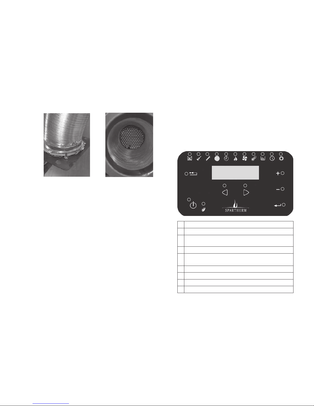
In the combustion air channel, a baffle plate made from perforated plate
is installed direct on the combustion air hood. A differential pressure is
measured in front of and behind this baffle plate. The control system is
connected direct to the measuring point using silicone hoses.
The flue gas fan is not given any rotational speeds as parameter, it is given
the value of a differential pressure. Depending on the draught in the chim-
ney, the flue gas fan is controlled so so that the differential pressure is
kept constant. This means that in event of a strong draught in the chimney,
the fan only rotates slowly whereas when the draught is weak, respec-
tively higher speeds are controlled. This creates constant conditions for the
combustion in the burner pot and the pellet stove is independent from the
draught in the chimney at the place if installation to a large extent as the
control system adapts to this.
The differential pressure also detects a complete chimney blockage and
then switches the device off. If the combustion chamber door is opened
during running operation, this is also detected as the differential pressure
now collapses. That is why this pellet stove does not have a door contact
switch. After a timer has elapsed, the extinguishing of the stove is initiated
when the door is opened:

GB 10
4.2 INFINITELY VARIABLE CAPACITY CONTROL
The heating capacity of the stove has been graded 5-fold (see operating
instructions). However, only the parameters for the data for stage 1 (min.)
and stage 5 (max.) are entered. The intermediate stages are calculated
automatically by the control system. The intermediate stages are started-up
softly via ramps and are not switched suddenly. In combination with the flue
gas fan that is also controlled via ramps, this results in a very low noise level
and a simple parameterization, as parameters do not have to be determined
separately for all intermediate stages.
5. OPERATING ELEMENTS
The pellet stove can be operated via the display on the stove. An infrared
remote control is also available for the most important functions:
5.1 THE DISPLAY
The first 3 symbols, at top left, are warnings. Adjacent to these 3 symbols
is the receiver for the remote control unit and a display that shows whether
a timer program is activated. With the menu buttons you can move to the
other 6 displays and then set them.
1
2
3 4 5 6 7 8 9 10 11 12 13
14
15
16
18
19
17
1On/Off switch
2ESC key (jump back) Also error code query
3Warning message: flue gas temperature too low or pellet deficiency
/ tank empty
4Warning message: clean the stove or flue gas outlet blocked
5Warning message: fault, please read the error code and contact
customer services
6Receiver for the infrared remote control
7Illuminates when the time switch program is active
8Current heating capacity (1, 2, 3, 4, Auto or Hi)
9Hot air blower performance stage (1, 2, 3, 4, 5 or Auto)

GB 11
GB
10 Room temperature and target temperature in °C
11 Pellet type selection (1, 2 or 3)
12 Time and time switch program
13 Service menu
14 Setting key (Jump back)
15
16 Enter key
17 Menu keys
18
19 Status lamp
5.2 THE REMOTE CONTROL
The most important settings of the stove can also be carried out using the
infrared remote control supplied.
To control the stove using the remote control, you need a free view of the
stove display. The receiver is located in the top section of the display. The
commands of the remote control are shown in the display.
For changing the battery, first pull the stop hook to the middle and hold t
there and then pull out the battery compartment, as shown on the back of
the remote control. Battery type: button cell CR2032, 3 Volt.
6. SERVICE MENU
The service menu is sub-divided into 13 levels. The level is displayed as a
value in square brackets, e.g., [ 5 ]. Levels 1 to 6 are freely accessible,
level 7 contains a password request for activating the levels 8 - 13.
Level Function
1Keypad lock (OFF, Lo or Hi)
2Display background brightness (1 to 5)
3Display indicator idling (1, 2, 3 and OFF)
4Volume of the signal transmitter (1 to 5)
5Software version of display (d…) and control system (c…)
6Manual continuous running of the screw feeder
(key function)
7Password query (r--0) for activation of higher levels
9Parameters, can be called up and edited
9Status display of all digital inputs
10 Status display of all analogue inputs
11 Status display of all digital outputs
12 Counter for different events, e.g., operating hours
13 Recording of different events, e.g., error messages
On/Off switch
(key 1)
Heating capacity higher
(Key 2)
Nominal room temperature
higher (Key 4)
Heating capacity lower
(Key 3)
…lower (Key 5)

GB 12
Level 1: Keypad lock
Here the display can be blocked against unauthorised operation as well
as for cleaning purposes. The keypad lock can be set in multi-levels. Use
the menu key to scroll to the service symbol (far to the right). Then set the
keypad lock using the adjustment keys + / -.. To confirm, press Enter.
• OFF: all display keys are activated and can be used
• Lo: the Enter key is blocked and thus, no values such as e.g., the set-
point room temperature can be adjusted. You can still switch On and Off.
• Hi: the Enter and the On / Off keys are blocked. The stove can no longer
be operated or adjusted via the display. We recommend that this setting
is used if the display has to be cleaned during running operation.
Note: the display locks are not effective for the remote control. That
operates independent from the keypad lock
Level 2: Display background brightness
When tapping on the key, the display lights up with full brightness. After the
key is not pressed for approx. 30 seconds, the display is dimmed again to
an adjustable value (1 - 5).
• Go to level 2 in the service menu using the + / - setting keys, a [ 2 ]
appears and then the current setting
• Press Enter, the current setting flashes.
• Select the desired background brightness with the + / - setting keys
• To confirm, press Enter
• Press the ESC key at the top left 2 times to return to the main menu
Level 3: Display representation when idling
Depending on the setting, the display shows different information approx. 2
minutes after pressing the key for the last time.
OFF: the display remains in the indicator last selected
1: the display shows the time and the current room temperature alternately
every 5 - 6 seconds
2: the display shows the current room temperature
3: the display shows the current time
For editing the settings, proceed as follows:
• Go to level 3 in the service menu using the + / - setting keys, a [ 3 ]
appears and then the current setting
• Press Enter, the current setting flashes.
• Select the desired operating mode with the + / - setting keys
• To confirm, press Enter
• Press the ESC key at the top left 2 times to return to the main menu
Level 4: Signal transmitter volume
The volume of the signal transmitter can be adapted here. The setting
range is between 1 to 5 and OFF. We recommend that you do not set this
too quite so that it can be perceived.
• Go to level 4 in the service menu using the + / - setting keys, a [ 4 ]
appears and then the current setting
• Press Enter, the current setting flashes.
• Select the desired volume with the + / - setting keys
• To confirm, press Enter
• Press the ESC key at the top left 2 times to return to the main menu
Level 5: Software versions
The version of the control system and display software can be queried here.
This information could be important for the customer services technician.
Service symbol

GB 13
GB
This value cannot be adjusted.
• Go to level 5 in the service menu using the + / - setting keys, a [ 5 ]
appears and then the current control software (c ....) version.
• Press Enter and the current version of the display software (d ….)
appears.
• You can toggle back and forth between the information using the Enter
key
• Press the ESC key at the top left 2 times to return to the main menu
Level 6: Screw feeder continuous running
This function can be used to continuously run the screw feeder. This is
required if the screw feeder has to be run empty.
The screw feeder pushes the pellets out of the tank forwards towards the
burner pot. If, e.g., you do not top up in time, first the feeder runs the tank
empty and then its feeder spiral. The firs extinguishes due to lack of fuel
and the stove generates a warning message (insufficient temperature) and
sets the warning lamp right to the left on the display.
Before a restart, the spiral of the feeder must be refilled with pellets again
to allow pellets to immediately fall into the burner pot when controlling the
pellet motor. The burner pot must be cleaned before carrying out this
function!
Proceed as follows to fill the feeder spiral:
• Go to level 6 in the service menu using the + / - setting keys, a [ 6 ]
appears and then OFF
• Press and hold Enter, an animation appears
As long as the Enter key is pressed, the pallet motor runs continuously. The
feed is interrupter automatically after 30 seconds for safety reasons and
Enter has to be pressed again. An audible signal sounds when cancelling.
You have to keep pressing Enter until the first pellets fall into the burner pot.
Then you can end this function Let go of Enter in order to stop the pellets
• Press the ESC key at the top left 2 times to return to the main menu
• Now the stove can be started
Level 7: Password request
The password activates levels 8 - 13. These are reserved for customer
services and especially trained personnel.
A warning is issued when adjusting the settings in these levels.
Incorrect settings can lead to severe property and personal injury.
Proceed as follows for activating:
• Go to level 7 in the service menu using the + / - setting keys,
[ r - - 0 ] appears
• Press Enter, a random number appears
• Calculate the checksum of this random number and add 1
• Press Enter and set the number calculated using th + / - setting keys
• Press Enter to confirm, ON appears
Level 8 - 13 are now activated. The random number is always different.
The service menu is activated as long as you are performing tasks in it. If
no key is pressed for 30 minutes, the service menu is locked again and the
password must be re-entered.
Example the random number shown is 4926. The access code is therefore
the checksum, thus, 4 + 9 + 2 + 6 = 21, plus 1, therefore 22.
Level 8: Parameter
Once the service menu has been activated (see level 7), in level 8 you can
view and edit the parameters.
A warning is issued when adjusting the settings in this level if you
do not have the respective professional knowledge. Incorrect set-
tings can lead to severe property and personal injury.

GB 14
Proceed as follows for editing the parameters:
• Go to level 8 in the service menu using the + / - setting keys,
[ P A r ] appears
• Press Enter, [ P 0 0 0 ] appears. That is the parameter no. 000.
• Use the menu keys to go to the desired parameter.
• Press Enter and the current setting value of the parameter appears
• The value can be edited using the adjustment keys + / -.
• To confirm, press Enter
• Press the ESC key at the top left 3 times to return to the home position
Note: the service menu stays open for 30 minutes. If you exit the service
menu in this time and then return to level 8 again, the password query is
omitted and you can access directly.
There is a separate list for the parameters and their function in the Appen-
dix at the end of this instruction. Several parameters are dependent on
each other. Therefore, always contact the customer services before making
changes.
Level 9: Digital inputs
Once the service menu has been activated (see level 7), in level 9 you can
query the status of the digital inputs. The allocation is as follows:
i01: Digital input for the safety temperature limiting device
i02: Wire jumper
i03: Open
i04: Open
F02: Flue gas fan rotational speed (only in combination with a Hall- IC
speed sensor, not relevant here)
Proceed as follows for viewing the status:
• Go to level 9 in the service menu using the + / - setting keys,
[ d i n ] appears
• Press Enter, [ i 01 ] appears. That is the digital input 01.
• Use the menu keys to go to the desired parameter.
• Press Enter and the current setting value of the parameter appears
• The value can only be read and not edited
• To confirm, press Enter
• Press the ESC key at the top left 3 times to return to the home position
The digital input i01 must be at OFF. If it is at On then the STB has triggered
and has not (yet) been reset.
Level 10: Analogue inputse
Once the service menu has been activated (see level 7), in level 10 you can
query the status of the analogue inputs. The allocation is as follows:
t03: Thermocouple 1 type K, current flue gas temperature in °C
t04: Thermocouple 2 type K, not used
t01: NTC 1 sensor, current room temperature in 1/10 °C,
thus, a display of 214 means 21.4°C
t02: NTC 2 sensor, not used
t05: NTC 3 sensor, not used
F01: External analogue signal, not used
PreS: Internal pressure sensor
Proceed as follows for viewing the status:
• Go to level 10 in the service menu using the + / - setting keys,
[ A i n ] appears
• Press Enter, [ t 03 ] appears. That is the snalogue input 03.
• Use the menu keys to go to the desired parameter.
• Press Enter and the current setting value of the parameter appears
• The value can only be read and not edited
• To confirm, press Enter
• Press the ESC key at the top left 3 times to return to the home position

GB 15
GB
PreS shows the current pressure difference that is kept constant by the
control system, see 4.1.
Level 11: Digital outputs
Once the service menu has been activated (see level 7), in level 11 you can
query the status of the digital outputs and also temporarily edit them (for
testing purposes). The test is cancelled after 30 seconds and the output is
reset to OFF. The allocation is as follows:
o01: Ignition element, can be set to OFF or On
o02: Flue gas fan, can be set from 1 to 255 and OFF
o03: Convection fan, can be set from 1 to 255 and OFF
o04: Pellet motor, can be set to OFF or On
o05: Not allocated
o06: Not allocated
Proceed as follows for viewing the status:
• Go to level 11 in the service menu using the + / - setting keys,
[ d o u t ] appears
• Press Enter, [ o 01 ] appears. That is the digital output 01.
• Press Enter and the current setting value of the digital output appears
(see above)
• The value can be read and edited. A reset is carried out automatically
after 30 seconds.
• Use the menu keys to go to the desired parameter.
• To confirm, press Enter
• Press the ESC key at the top left 3 times to return to the home position
With the digital output functions o02, o03 and o04, one can e.g., test if
these components are still functional.
Level 12: Service counter
Once the service menu has been activated (see level 7), in level 12 you can
query different counters for different events. The allocation is as follows:
Sc00: Number of ignition processes
Sc01: Number of overtemperature deactivations
Sc02: Number of faulty ignitions
Sc03: Operating hours on the main voltage
Sc04: Operating hours in heating mode
Sc05: Time until the next service
Sc06: Reseting the service timer
Proceed as follows for viewing the counter:
• Go to level 12 in the service menu using the + / - setting keys,
[ S c ] appears
• Press Enter, [ S c 0 0 ] appears. That is the counter 00.
• Press Enter and the current value of the counter appears
• The value can only be read and not edited Exception: Sc06 can be used
to reset the service timer
• Use the menu keys to go to the desired parameter.
• To confirm, press Enter
• Press the ESC key at the top left 3 times to return to the home position
The service timer indicates the time until the next service, it is however not
selected and programmed.
Level 13: Recording of events / error buffer
Once the service menu has been activated (see level 7), in level 13 you can
query an error buffer. Up to 15 events can be recorded, thereafter the oldest
event is overwritten automatically. The data records are L001 to L014. The
allocation is as follows:
L000: Newest error, last entry
L014: Oldest entry, first entry

GB 16
7.1 REAR WALL
The rear wall is in two parts. The top part can be hung-out by lifting it. Then
the bottom part can also be removed by lifting it.
Proceed as follows for reading out:
• Go to level 13 in the service menu using the + / - setting keys, [ L O
G S ] appears
• Press Enter, [ L 0 0 0 ] appears. That is the newest error recorded last.
• Use the menu keys to go to the desired error buffer.
• Press Enter, first the year value of the error recording appears
• Using the right menu key, you can scroll to the following data: date, time
and the three digit error code
• Press the ESC key at the top left 3 times to return to the home position
A table with the error codes can be found at the end of the service
instructions.
7. MECHANICAL COMPONENTS
The pellet stove Mellino is supplied ready mounted. The cladding does not
have to be assembled on location.
If it should be necessary to remove parts of the cladding, the following notes
must be observed:
• Opening the cladding or the replacement of parts on the Mellino must
only be carried out by an instructed specialist.
• Disconnect the power plug from the socket before opening the cladding
each time!
• The cladding must only be removed when the stove is switched off and
has cooled down.
• Take care that the pellet supply tank is close so that no tools can fall
into it.

GB 17
GB
7.2 REMOVING THE COMBUSTION CHAMBER DOOR
• Open the combustion chamber door.
• Remove the retaining spring on the top door pin (image).
• Lift the door upwards and out of the bottom guide.
• Pull the door slightly to the front and when lowering, pull out of the top
guide.
•
The assembly is carried out in the reverse order.
7.3 COMBUSTION CHAMBER LINING
The firebox lining comprises Vermiculite and has the following structure:
1= Side part, left side
2= Side part, right side
3= Deflection plate
4= Back wall
5= Cornice
Removing the securing spring Lift the door and pull to
the front

GB 18
7.5 REMOVING THE SIDE CLADDING
• Remove the top plate.
• Remove the protective grid by undoing the two hexagon socket screws
(image 1)
• Hang out both sides of the back wall (see 5.1)
• Removing the combustion chamber door (see 5.2)
• Unscrew the screw fittings (6 x hexagon socket screws) in the door
frame (image 2)
• Undo the cladding at the back of the body (image 3 Detail D and E).
• Unscrew the holding angle (image 4 and 5 Detail F)
• Unscrew the holding angle of the tank cover frame (image 6)
• Unscrew the nuts of the left and right screw fittings of the tank cover
frame (image 7 and 8)
• Slightly lift the side cladding from behind and pull out of the guide to
the front.
• If necessary, remove the connecting line from the operating panel.
The assembly is carried out in the reverse order.
7.4 SCREW FEEDER
• Removing the gear motor (see „8.3. Screw feeder drive“).
• Remove the adjusting ring.
• Slowly loosen the retaining plate (4 screws, see image below).
• Hold up the empty pellet bag to collect the pellets
• Remove the distance disc.
• Carefully screw out the feeder, collecting the pellets in the process
The assembly is carried out in the reverse order. When inserting the feeder,
take care that the feeder slips safely into the top sliding bearing. We recom-
mend that you apply a thin coat of copper paste to all sides of the bottom
feeder bearing.
Note: after assembling and tightening the retaining plate, the feeder should
be able to be turned lightly by hand. Pic. 1

GB 19
GB
Pic. 2
Pic. 3
Pic. 4 Pic. 5

GB 20
8. ELECTRICAL COMPONENTS
If it should be necessary to remove or exchange electric components, the
following notes must be observed:
• The replacement of parts on the Mellino must only be carried out by an
instructed specialist.
• Disconnect the power plug from the socket before opening the cladding
each time!
• The components must only be removed when the stove is switched off
and has cooled down.
• Take care that the pellet supply tank is close so that no tools can fall
into it.
8.1 MAINS FUSE
The Mellino is safeguarded using a mains fuse F1 = T2A (10.3 x 38 mm). A
replacement fuse is also in the fuse holder.
• Remove the power plug from the socket.
• Remove the top and bottom back wall.
• Unscrew the cover plate of the fuse box.
• Open the F1 fuse holder (see „Appendix b: Circuit diagram terminal
strip X1“).
• Remove the fuse and insert the replacement.
Attention: if the fuse has tripped, find out the reason for the fuse tripping
and eliminate this before replacing the fuse.
Pic. 6
Pic. 7
Pic. 8
Other manuals for Mellino
1
Table of contents
Other Spartherm Pellet Stove manuals
Popular Pellet Stove manuals by other brands

EasyFire
EasyFire EF5001C-AL Installation & operating instructions

Napoleon
Napoleon NPS45 Installation and operating instructions

ADURO
ADURO H1 user manual

Breckwell
Breckwell Tradition P23I owner's manual

EdilKamin
EdilKamin MYA Installation, use and maintenance

IronStrike
IronStrike Bella Installation and operation manual

Breckwell
Breckwell Tradition P24FS owner's manual

WiseWay
WiseWay GW1949 Installation and operating manual

Quadra-Fire
Quadra-Fire MTVERNON-AE-CSB owner's manual

Alfa Plam
Alfa Plam LUCA Installation, operation and maintenance manual

HAMPTON BAY
HAMPTON BAY GCI60 owner's manual

Haas+Sohn
Haas+Sohn HSP 8 CATANIA-II-RLU Installation and operating manual