ASHOK LEYLAND Optare Tempo X1260 User manual

This handbook covers the following Optare Tempo models with standard
Euro 5 mechanical specification.
The information appearing in this handbook is applicable to vehicles
manufactured at the time of printing. The manufacturer therefore
reserves the right, while retaining basic features of the models described
and illustrated herein, to make at any time and without necessarily
bringing this book up to date, any alterations to units, parts or accessories
deemed convenient for improvement or commercial reasons.
X1260 12605 2490 3060
Introduction Page 2
Instruments and Controls Page 8
Routine Maintenance Page 27
Saloon Amenities Page 30
Electrical Page 31
Driving Instructions Page 36
Emergency Instructions Page 39
General Maintenance Page 47
Technical Data Page 63
MODEL LENGTH WIDTH HEIGHT
All dimensions in millimetres
SCOPE
DESIGNATION
CONTENTS
CONTENTS
1
Hurricane Way South, Sherburn in Elmet, Leeds, LS25 6PT, UK
TELEPHONE: +44 (0) 8434 873 200 FAX: +44 (0) 8434 873 290

Your Optare Tempo is designed and built for safe and reliable use.
Items of safety are indicated with the symbol:
This hand book is a guide towards the safe and efficient use of your
Optare Tempo.
Service information, other than routine/daily checks is not contained
within this handbook.
Service information is contained in separate documentation and is
available from Unitec.
Spare parts are available from Unitec.
Prior to the vehicle being driven on the public highway, all drivers
(and crew) must be conversant with position, access and
operation of emergency exits, fire extinguisher(s), first aid kit(s),
emergency engine stops, battery isolation switch and safety
devices.
Drivers, crew and passengers should always use seatbelts when
travelling in the vehicle. The seatbelts must be correctly adjusted
and never used to restrain more than one person. Children
(according to size) should always be carried in a restrained carry
cot, child seat or child booster cushions with adult belts.
Do not place flammable or pressurised liquid near any hot air
outlets or windscreen demister louvres.
INTRODUCTION
INTRODUCTION
PASSENGER SAFETY
SEAT BELTS (IF FITTED)
HEATER DUCTS AND HOT AIR OUTLETS
2

When checking items in the engine compartment with the engine
running, ensure that no article of clothing can become entangled with
the drive belts to auxillary components.
BEING TOWED (PAGE 45 )
JACKING THE VEHICLE (PAGE 46 )
REFITTING WHEELS (PAGE 47 )
REPLACING ANY FUSES (PAGE 31 )
WHEN LEAVING YOUR VEHICLE UNATTENDED
DO Always remove the ignition key where fitted even in your own
garage, close all windows completely and secure all doors.
Always park your vehicle where it can be seen at night, park in a
well lit area.
a. DO NOT Leave children or animals in the vehicle
when unattended.
b. DO NOT Leave valuables on view.
c. DO NOT Leave the vehicle documents in the vehicle. Stringent regulations governing the design and manufacture of
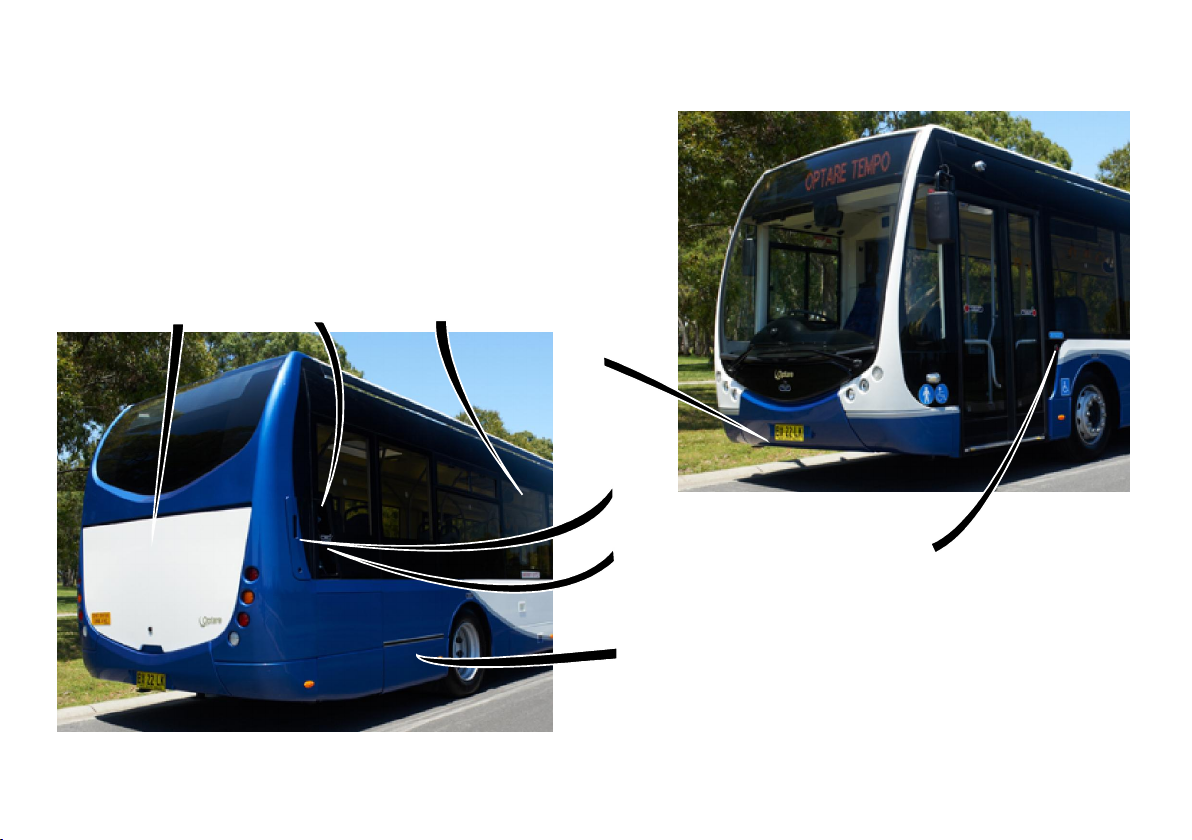
passenger service vehicles are imposed in the United Kingdom.
The Tempo is built to the C&U / DDA standards. Alterations to the
vehicle after purchase (e.g. change of settings or adjustments,
fitting unsuitable or unapproved parts) can result in a deviation
from the C&U / DDA specification. Such deviations may have
legal consequences, in which case Optare can except no liability
in respect of vehicle failure caused directly or indirectly by such
alterations.
Parts fitted to the Optare Tempo must be of the same
manufacture and specification as fitted by Optare as original
equipment. Spare parts and materials are available from Unitec
and/or in certain cases from suppliers of original equipment to
Optare. There are no alternatives to these parts and materials,
and even those marketed making such claims must not be used.
Always keep cleaning fluids, oils, hydraulic fluids, greases safely locked
away.
Always read the health & safety precautions on the containers. Avoid skin
contact.
MAINTENANCE
UNDER THE VEHICLE
THE ENGINE COMPARTMENT
Never work under a vehicle that is only supported on a hydraulic jack.
Use rigid supports which correlate to the maximum unladen weight.
INTRODUCTION
READ THIS HANDBOOK PRIOR TO:-
VEHICLE MODIFICATIONS
3

EXAMPLE PLATE
Vehicle Identification Number (V.I.N.) plate is located
below the entrance partition and is embossed to
provide the relevant information.
In addition the chasis/Vehicle Identification Number is
stamped on the main structure in the engine bay.
Vehicle
Identification
Number
X SAB28000000000001 X
17,000 17,000
6,300 6,700
11000
1.3
11000
MERCEDES OM906LA
2.5 METRES
12.0 METRES
X1200
INTRODUCTION
VEHICLE IDENTIFICATION
4

STEERING BOX DATA PLATE
ENGINE TYPE PLATE
Use the information on the engine type plate when requiring
service or sourcing parts for your engine.
MERCEDES ENGINE
The type plate is located on the rear left of the engine (arrow), on
the joint to the valve case, diagonally above the air compressor.
1: Engine type reference. 2: Engine number.
Use the information on the data
plate when discussing service or
sourcing parts for your gearbox.
The data plate is to be found on the lefthand side of gearbox at
the output shaft end viewed from the front of the vehicle.
Steering box data plate is to be found on the steering box body
just below the input shaft end cover.
example type plate
TRANSMISSION DATA PLATE - ALLISON
INTRODUCTION
5

INTRODUCTION
CUSTOMER HELPLINE
OPERATION
FRONT AXLE DATA PLATE
REAR AXLE DATA PLATE
The front axle data plate can be found on the left side of the axle beam
facing towards the rear of the vehicle.
Use the information on the data plate when discussing service or sourcing
parts for the axle.
The rear axle data plate can be found on the underside of the diff
casing.
Use the information on the data plate when discussing service or
sourcing parts for .the axle
Rear axle data plate
Front axle data plate
6
In the event of a vehicle warranty defect occurrence, the
operator should contact by OPTARE PRODUCT SUPPORT
telephoning , between the hours of 8am & 08712 301324
5pm Mon - Fri.
The product support operator will obtain all relevant details
including:
a) Operators name & contact Tel No.
b) Vehicle identification number (VIN).
c) Registration number
d) Mileage
e) Vehicle location
F) Nature of fault
Necessary arrangements will be made to rectify the fault,
Optare agents will not attempt to repair unattended
vehicles unless previously advised.
VOR occurrences will be attended to the next working day
(depending on parts availability).
Optare will invoice an operator for any job which is
subsequently found not to be covered by the vehicle
warranty, (an additional administration charge will be
levied).
1.
2.
3.
4.

INTRODUCTION
VEHICLE EXTERNAL LAYOUT
1. Entrance door open control
2. Emergency escape
3. Fuel filler
4. Battery access cover
5. Towing eye (1" B.S.F. Female thread)
6. Engine access
7. Emergency engine stop
8. Adblue filler (Mercedes engined vehicles only)
1
5
7
2
7
3
8
4
6

INSTRUMENTS & CONTROLS
INSTRUMENT PANEL
8
(TFT) = shown on central TFT display
15. Indicator Right
16. Tachograph Warning
17. Front Brake Circuit Pressure
18. Engine Coolant Temperature Gauge (TFT)
19. Fuel Gauge (TFT)
20. Not Populated
21. Not Populated
22. Not Populated
23. Switch between CCTV view / TFT display
24. Not Populated
25. Engine Oil Level / Pressure Gauge
26. Adblue Gauge (TFT)
27. Rear Brake Circuit Air Pressure
1. Speedometer (MPH / KPH)
2. Indicator Left
3. Trip, Time, Date, Temp, Mileage (TFT)
4. Park Brake On
5. Retarder On
6. Gearbox Oil Temperature High
7. Coolant Temperature High
8. High Beam On
9. Engine Fault Warning (Red)
10. Engine Fault Warning (Amber)
11. Engine Oil Pressure Low
12. ABS System Fault
13. Dip Beam On
14. Emissions Fault
1
2
345678910 11 12 13 14 15
16
17 18 19 20 21 22 23 24 25 26 27

INSTRUMENTS & CONTROLS
WARNING / INFORMATION LIGHTS
9
The warning / function lights on the Optare vehicle consist of four colours, RED, AMBER, BLUE and GREEN. The colour of the light indicates the level of
response required based on the type of warning indicated:
RED - WARNING LIGHTS - Stop immediately it is safe to do so, do not use the vehicle until the fault has been rectified and the warning light
extinguishes normally.
AMBER
BLUE - FUNCTION LIGHTS - Illuminates when a function is operating normally, however, if the function is switched off and the light remains
GREEN on (steady or flashing), then attention is required at the earliest opportunity. The vehicle can be operated normally with this light illuminated.
PARK BRAKE
(RED)
Illuminates when the park brake is on.
HIGH BEAM
(BLUE)
Illuminates when the HIGH beam is switched on when the or
headlamp flash is operated.
HEADLAMP
( )GREEN
ABS ACTIVE / FAULT
(AMBER)
ABS
This lamp will briefly illuminate when the ignition is switched on and will
extinguish after the ABS self check has found no system faults.
DIRECTIONAL INDICATORS left / right
(GREEN)
TACHOGRAPH WARNING
( )RED
LOW BRAKE CIRCUIT AIR PRESSURE
( )RED
Flashes when L/H or R/H indicators are switched on.
Illuminates when a fault is detected with the tachograph
communication system.
Illuminates when low air pressure is detected in the braking circuit.
T
Illuminates when the switched on HEADLAMPS are in the dipped beam
position.
ASR
ANTI SLIP REDUCTION
(RED)
(When specified)
Illuminates when the ASR system is active, eg, eliminating wheel spin.

INSTRUMENTS & CONTROLS
10
WHEELCHAIR PASSENGER BELL
SALOON BELL
Illuminates when the wheelchair station bell is activated, lamp is
extinguished when the entrance doors are opened.
State - Pressed
State - latched (not reset)
State - Pressed
State - latched (not reset)
Illuminates when the bell has been activated, extinguishes when saloon
the entrance doors are opened.
BRAKE LIGHT FAULT
( )AMBER
Illuminates when there is a brake light fault. If the lamp illuminate whilst
driving, have the brake lights checked at the earliest opportunity.
Illuminates when water is detected in the fuel filter. If the lamp illuminate
whilst driving, have the fuel system checked at the earliest opportunity.
Illuminates when a front or rear brake pad has reached it’s minimum wear
thickness.
If the light illuminates while driving, stop immediately it is safe
to do so, have the brake pads checked / replaced as necessary.
Illuminates when the windscreen washer fluid level is low.
If lamp illuminates, have the windscreen washer bottle replenished as
soon as possible.
BRAKE PAD WEAR LIMIT
(AMBER)
WINDSCREEN WASH LOW
( )AMBER
EMERGENCY ESCAPE HAMMER
( )RED
Illuminates when the emergency escape hammer is removed from it's
holster.
WARNING / INFORMATION LIGHTS

INSTRUMENTS & CONTROLS
11
WARNING / INFORMATION LIGHTS
REAR ENGINE DOOR OPEN
(RED)
Illuminates when the rear engine door is opened.
If lamp illuminates while driving, stop immediately it is safe to do so.
COMMUNICATIONS FAULT
(RED)
Flashes quickly and sounds the warning buzzer when the vehicle
develops an J1939 communications failure.
If light illuminates whilst driving, contact your nearest Optare dealer.
MUX
COMMS
KNEELING SUSPENSION
(RED)
Illuminates when the kneeling suspension switch is activated, the lamp
extinguishes when the vehicle is raised to normal ride height.
AIR SUSPENSION PRESSURE
(AMBER)
Lamp illuminates when low air pressure is detected in the suspension
circuit.
!
VEHICLE LOWER
(RED)
Illuminates when the vehicle lower switch is activated, the lamp
extinguishes when the vehicle is returned to normal ride height.
BATTERY GUARD
(AMBER)
The battery guard system shuts down all electrical systems if the
battery voltage falls below 23 Volts.
Battery guard is disabled when the engine is running.
Warning light illuminates 30 sec’s before system shutdown.
EMERGENCY DOOR OPEN
( )RED
Illuminates when a door is opened.
If the lamp illuminates while driving stop immediately it is safe to do so.
EMERGENCY WINDOW OPEN
( )RED
Illuminates when an emergency window is opened.
If the lamp illuminates while driving stop immediately it is safe to do so.
AIR FILTER RESTRICTED
(AMBER)
Acts as a warning light to indicate the engine air filter has become
blocked. If lamp illuminates whilst the engine is running, have the engine
air intake system checked immediately it is safe to do so.

INSTRUMENTS & CONTROLS
12
WARNING / INFORMATION LIGHTS
Lamp warns of low air pressure on the front, rear or park brake
circuits.
If the light illuminates while driving, stop immediately it is safe to do so.
LOW AIR PRESSURE
(RED)
COMMUNICATIONS FAULT
(AMBER)
Flashes quickly and sounds the warning buzzer when the vehicle
develops an J1939 communications failure.
If light illuminates whilst driving, contact your nearest Optare dealer.
J1939
COMMS
FERRY LIFT
(RED)
Illuminates when the ferry lift switch is activated, the lamp extinguishes
when the vehicle is returned to normal ride height.
ENGINE IDLE SHUTDOWN
(AMBER)
If the vehicle is left at idle with a gear selected, after a pre-determined period
of time (usually 7 mins), the transmission temperature warning light will flash
and if ignored the engine will shut down.
Selecting neutral on the gearshift is necessary before a drive gear can then be
selected.
CHECK TRANS
(AMBER)
LOW TRANSMISSION OIL LEVEL
(AMBER)
Illuminates when the transmission develops a fault
If the light illuminates while driving, immediately have the vehicle
returned for service.
The drive function of the vehicle will not be disabled.
Illuminates when the transmission oil level is low.
If the light illuminates while driving, immediately have the vehicle
returned for service.
RANGE INHIBIT
(GREEN)
RANGE
INHIBIT
Illuminates when gear selection is attempted but conditions for gear
selection are not met e.g. Engine speed too high, foot brake not pressed
etc.
OVER TEMP
( )RED
OVER
TEMP
Illuminates when any of the transmission components has
reached a thermal limit. If lamp illuminates whilst driving, stop
immediately it is safe to do so and allow the transmission to cool. Once
the transmission has cooled, the warning light will extinguish allowing
normal operation of the vehicle.

INSTRUMENTS & CONTROLS
13
WARNING / INFORMATION LIGHTS
Illuminates when the engine coolant level is too low.
If the lamp illuminates while driving stop immediately it is safe to do so.
After allowing the engine to cool down, top up the coolant before
continuing the journey.
LOW COOLANT LEVEL
(AMBER)
LOW FUEL LEVEL
(AMBER)
Illuminates when the fuel level in the tank is low.
10% fuel remaining - lamp illuminates constant.
5% fuel remaining - lamp flashes.
REAGENT WARNING LIGHT
(AMBER)
See pages 19,20, & 21.
LOW BATTERY CHARGE
FROM ENGINE ALTERNATOR
(RED)
1
Illuminates when the ignition switch is turned on. If the lamp does not
extinguish when the engine is running, the fault must be identified and
rectified.
ENTRANCE / EXIT DOOR
( RED)WHITE /
ENTRANCE DOOR RAMP
( RED)WHITE /
Illuminates WHITE when door is open.
Illuminates RED when door develops a fault or operated via the
emergency controls.
Warning function is reset when drivers control is operated.
Position of symbol within plan view outline, indicates location of door on
vehicle.
Illuminates WHITE when ramp is deployed.
Illuminates RED when ramp develops a fault, or if deployment is
attempted under unsatisfactory conditions e.g. Entrance door closed,
vehicle moving etc.
Warning function is reset when drivers control is operated.

INSTRUMENTS & CONTROLS
14
WARNING / INFORMATION LIGHTS
AIR FILTER RESTRICTED
(RED)
Acts as a warning light to indicate the engine air filter has become blocked.
If lamp illuminates whilst the engine is running, have the engine air intake
system checked immediately it is safe to do so.
Lamp illuminates when the halt brake system is active.
The halt brake system applies the service brakes when:-
The vehicle is knelt.
The entrance ramp is deployed.
Neutral gear is selected.
(When )fitted
HALT BRAKE
( )RED
H
FUEL LEVEL
ENGINE OIL LEVEL / PRESSURE
ENGINE COOLANT TEMPERATURE
Number of bars reduce as the fuel tank is depleted.
Ignition ‘ON’ only -
The colour of the bars indicate the oil level status:
WHITE bars - Oil level within correct range.
RED bars - Oil level out of range.
High number of bars indicate oil level is too high.
Low number of bars indicate oil level is too low.
Engine running -
Displays oil pressure gauge:
WHITE bars indicate correct oil pressure.
RED bars indicate incorrect oil pressure.
Number of bars increases as the engine coolant
temperature increases.
Bars turn ‘RED’ when engine coolant temperature is too
hot.
FUEL
TEMP
ADBLUE LEVEL
Number of bars reduces as the adblue tank is depleted.
ADBLUE
FIRE SUPPRESSION ACTIVATED
( )RED
FIRE
Illuminates when the fire suppression system is activated.
If lamp illuminates whilst driving, stop immediately it is safe to do so and
follow your company emergency procedures.

INSTRUMENTS & CONTROLS
15
WARNING / INFORMATION LIGHTS
RETARDER ACTIVE
(RED, AMBER, BLUE)
RED, Stage 1 failure - This indicates a fault with the retarder ECS. The
vehicle should be stopped immediately it is safe to do so and have the
problem rectified (a time period has been allowed to safely stop 5 Min
and isolate the vehicle).
AMBER, Stage 2 failure - This condition is activated if the vehicle is
kept in “vehicle moving phase” for more than , 5 Min’s In this condition
throttle control will be lost.
BLUE, Foot brake fault - This lamp indicates a brake pedal fault.
!
WAIT
TO
START ( )Cummins only
BATTERY GUARD
(AMBER)
WAIT TO START
(AMBER)
The battery guard system shuts down all electrical systems if the
battery voltage falls below 23 Volts.
Battery guard is disabled when the engine is running.
Warning light illuminates 30 sec’s before system shutdown.
Wait to start lamp illuminates after ignition is switched on, the lamp
stays on while the engine ECU performs it’s system checks.
The engine cannot be started until this lamp is extinguished.
The lamp will extinguish after all the ECU system checks are satisfied.
ENTRANCE / EXIT DOOR
( RED)WHITE /
ENTRANCE DOOR RAMP
( RED)WHITE /
Illuminates WHITE when door is open.
Illuminates RED when door develops a fault.
Position of symbol within plan view outline, indicates location of door on
vehicle.
Illuminates WHITE when ramp is deployed.
Illuminates RED when ramp develops a fault.

INSTRUMENTS & CONTROLS
16
WARNING / INFORMATION LIGHTS
ADBLUE WARNING LIGHTS
ADBLUE QUALITY REDUCED
(AMBER)
ADBLUE QUALITY REDUCED (10 Hrs of operation)
( )AMBER
ADBLUE QUALITY REDUCED (20 Hrs of operation)
( )AMBER
Inducement light (solid). Illuminates after
detection of incorrect adblue quality.
Inducement light (solid), Inducement Limiter
(solid). Max engine torque is limited to 75% of peak torque.
Inducement light (solid), Inducement Limiter
(flashing 1Hz). Vehicle speed is limited to 20 Km/h.
LOW ADBLUE CONSUMPTION
(AMBER)
LOW ADBLUE CONSUMPTION (10 Hrs of
operation) (AMBER)
LOW ADBLUE CONSUMPTION (20 Hrs of
operation) (AMBER)
Inducement light (solid), AWL light
(solid), MIL light (solid). Illuminates when
detecting low Adblue consumption.
Check Adblue system.
Inducement light (solid), Inducement
limiter (solid), AWL light (solid), MIL light (solid).
Illuminates when detecting low Adblue
consumption for 10Hrs of engine operation.
Max engine torque is limited to 75% of peak
torque.
Inducement light (solid), Inducement
limiter (flashing 1Hz), AWL light (solid), MIL light
(solid). Illuminates when detecting low Adblue
consumption for 20Hrs of engine operation.
Vehicle speed is limited to 20Km/h

INSTRUMENTS & CONTROLS
17
ADBLUE WARNING LIGHTS
INTERRUPTION OF ADBLUE DOSING
(AMBER)
INTERRUPTION OF ADBLUE DOSING (10 Hrs of
operation) ( )AMBER
INTERRUPTION OF ADBLUE DOSING (20 Hrs of
operation) ( )AMBER
Inducement light (solid). Illuminates after
interruption of adblue dosing.
Inducement light (solid), Inducement Limiter
(solid). Max engine torque is limited to 75% of peak torque.
Inducement light (solid), Inducement Limiter
(flashing 1Hz). Vehicle speed is limited to 20 Km/h.
ADBLUE MONITORING SYSTEM COMPONENT
FAILURE (AMBER)
ADBLUE MONITORING SYSTEM COMPONENT
FAILURE (AMBER) (10 Hrs of operation)
ADBLUE MONITORING SYSTEM COMPONENT
FAILURE (AMBER) (20 Hrs of operation)
Inducement light (solid).
Illuminates when detecting monitoring component
failure.
Check Adblue system.
Inducement light (solid), Inducement limiter
(solid). Illuminates when detecting monitoring
component failure for 10Hrs of engine operation.
Max engine torque is limited to 75% of peak torque.
Inducement light (solid), Inducement limiter
(flashing 1Hz). Illuminates when detecting monitoring
component failure for 20Hrs of engine operation.
Vehicle speed is limited to 20Km/h

INSTRUMENTS & CONTROLS
18
INSTRUMENT PANEL SWITCHES
BATTERY MASTER
Press once - Switches on the vehicles electrical power.
Press again - Turns off the vehicles electrical power.
IGNITION SWITCH
Press once - Switches on the systems.
Press again - Turns off the systems
START SWITCH
Depress to enable drive.
HAZARD WARNING LIGHTS
Press once - Activates the hazard warning lights.
Press again - Turns off the hazard warning lights.
AUDIBLE WARNING
The driver should familiarize himself with the sound of the warning
buzzer.
IF THE BUZZER SOUNDS WHILE DRIVING, STOP IMMEDIATELY IT
IS SAFE TO DO SO.
THE BUZZER IS ACTIVATED BY THE FOLLOWING:-
1. Emergency door lock handle activated.
2. Low air pressure in braking circuits.
3. Low coolant level.
4. Low engine oil pressure.
5. Engine over heat.
7. Low battery charge (alternator failure).
8. Fire suppression system active (optional).
9. Ramp deployment (powered ramp) or (manual ramp when
requested).
10. Vehicle kneeling.

INSTRUMENTS & CONTROLS
19
SIDE CONSOLE SWITCHES
SALOON LAMPS - L/H, R/H
Press once - Saloon lamps illuminate.
Press again - Saloon lamps extinguish.
CAB LIGHT
Press once - Cab lamp illuminates.
Press again - Cab lamp extinguishes.
REAR FOG LAMPS
Press once - fog lamps illuminate.
Press again - fog lamps extinguish.
Fog lamps can only be illuminated while headlamps are switched on.
DOOR OPEN/CLOSE
HEADLAMPS
KNEELING SUSPENSION
SIDE LIGHTS
Press once - Doors open.
Press again - Doors close.
Press once - Headlamps illuminate to full power.
Press again - Headlamps extinguish or dims to 20% of full power
(optional configuration through Actia setup program).
Press once - Vehicle lowers.
Press again - Vehicle rises.
Press once - Side lights illuminate.
Press again - Side lights extinguish.
DEMISTER OPERATION
Press once - for slow speed demister blowers.
Press again - for fast speed demister blowers.
Press again - to turn off demister blowers.

INSTRUMENTS & CONTROLS
20
SIDE CONSOLE SWITCHES
SALOON HEATER BLOWERS
Press once - to start saloon heater blowers.
Press again - to stop saloon heater blowers.
INTERMITTENT REVERSE
BLEEPER (MUTE)
AUXILIARY HEATER
Press once - to turn reverse bleeper off.
Press again - to turn reverse bleeper on.
Switch can only be operated when reverse gear is selected.
Press once - to turn
Press again - to turn
R
AUX
HEATER
SPEEDOMETER / ODOMETER
The standard speedometer /odometer indicates road speed in miles per
hour and kilometers per hour.
WIG / WAG LIGHTS
Press once - to set lights to auto (flash when entrance doors are open).
Press again - to set lights flashing constantly.
Press again - to turn off the lights.
WIG
WAG
Table of contents