Alexander Dennis Trident 2 User manual

Operation Guide
TRIDENT

2
Publication Number 2256 ~ Trident 2-axle chassis
Used on & after Chassis No 3158 (including 3065) October 2003 (10/04)

3
Introduction
The purpose of this operation guide is
to provide drivers with information to
help them to operate their vehicles
safely and efficiently. It is
recommended that it is kept with the
vehicle.
Care and attention given at the right
time will ensure efficient and
satisfactory performance. Periodic
attention is necessary, and should help
to avoid breakdowns. Never run the
vehicle in a doubtful condition, always
report back to the garage for inspection
and attention.
Vehicles manufactured by Alexander
Dennis, when delivered, comply with all
current Department of Transport
Regulations and Codes of Practice
appertaining.
Whilst every effort is made to ensure
the information given in this handbook
is correct at the time of going to print,
the Alexander Dennis policy is one of
continuous improvement and the right
to change specifications and
equipment without notice is reserved.
In all communications quote the
relevant V.I.N. and engine number.
This will ensure prompt attention.
Gross Vehicle Weight and Axle
loadings are based upon the maximum
seating capacity of the vehicle, as
delivered, (including Driver).
Alexander Dennis
Dennis Way
Guildford
Surrey
GU1 1AF
England
Telephone: + 44 (0)1483 571271
Fax: + 44 (0)1483 301696
Alexander Dennis
91 Glasgow Road
Falkirk
FK1 4JB
England
Telephone: + 44 (0)1324 621672
Fax: + 44 (0)1324 633120
It is recommended that this
handbook is kept with the
vehicle.
This handbook is based on
the Trident 2 axle chassis with
Euro 3 engine and original
equipment fitted at the
factory. You should therefore
bear in mind that the
bodybuilder may have made
changes to the vehicle.
For this reason, you may find
illustrations and/or certain
parts of the text in this
handbook which do not
correspond exactly to the
particular situation on your
own vehicle.

4
Introduction
Please take note of the following
symbols, used throughout this manual
which identify any health hazards or
instructions to prevent any personal
injuries or damage to the vehicle.
Operational
• The maximum permitted laden
weight is identified on the VIN
plate.
• The maximum passenger
carrying capacity is identified in
the cab area.
• When a defect is identified, it
could cause serious problems
or deterioration. This must be
rectified prior to the vehicle
going into service.
Items marked with this sign are fitted
as options.
NOTE
Text with this heading and a
shaded background refers to
special methods, features or
procedures.
CAUTION
Text with this heading and a
shaded background is a
reminder of an operation
which, if not carried out with
due care, could involve the
risk of damage to material.
WARNING
Text with this heading and a
shaded background is a
reminder of an operation
which, if not carried out with
due care, could involve the
risk of personal injury.
Key to Symbols Buyer's Obligations Options
CAUTION
It is imperative that all
maintenance procedures are
complied with and records of
all work are kept and are
available to view.
NOTE
The failure to comply with
these requirements could
cause mechanical or
structural failure and will
invalidate the warranty.

5
Table of Contents
Introduction . . . . . . . . . . . . . . . . . . 3
Key to Symbols . . . . . . . . . . . . . . . 4
Table of contents . . . . . . . . . . . . . . .5
General Description . . . . . . . . . . . . 7
Vehicle Identification Plate . . . . . . . 8
Vehicle Identification Sheet . . . . . . . 9
Controls and Instruments 10 - 22
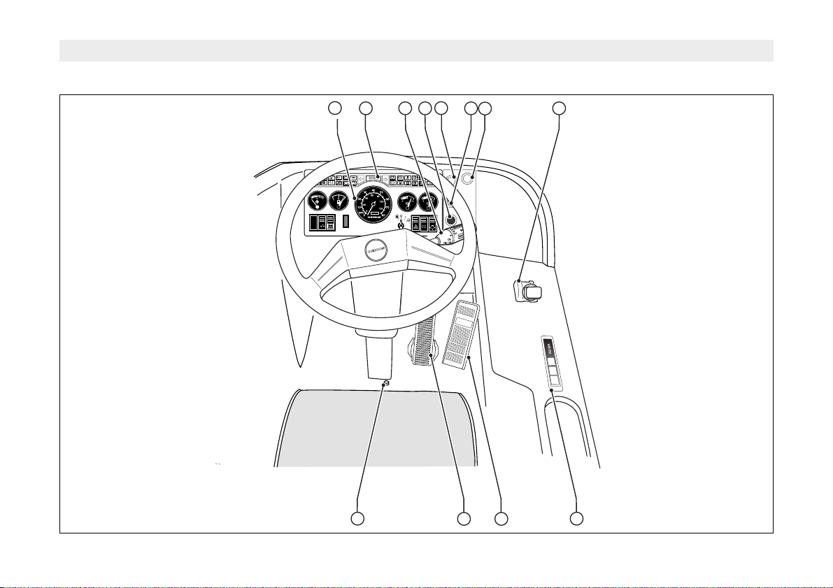
Control Layout . . . . . . . . . . . .10 - 11
Instrument Panel . . . . . . . . . . 12 - 13
Warning Lights . . . . . . . . . . . .14 - 17
Multi Function Switch . . . . . . . 18 - 19
Automatic Gearbox Selector . . . . . 20
Suspension - Kneeling System . . . 21
Ferry lift . . . . . . . . . . . . . . . . . . . . .22
Parking Brake . . . . . . . . . . . . . . . . 22
Steering Column . . . . . . . . . . . . . .22
Accelerator Pedal . . . . . . . . . . . . .23
Brake Pedal . . . . . . . . . . . . . . . . .23
Starting and Driving 24 - 31
CRT Exhaust - Fuel . . . . . . . . . . . 24
Engine . . . . . . . . . . . . . . . . . . . . . 25
Automatic gearbox . . . . . . . . 26 - 29
Transmission Brake Operation . . . 29
Speed Control Humps . . . . . . . . . .29
Guided Busways . . . . . . . . . . . . . .29
Stopping . . . . . . . . . . . . . . . . . . . 30
Engine Shutdown . . . . . . . . . . . . . 30
Engine Emergency Stop . . . . . . . . 30
Batteries & Carrier . . . . . . . . . . . . 31
Posilock Refuelling . . . . . . . . . . . .32
Maintenance 33 - 43
Summary . . . . . . . . . . . . . . . .33 - 35
Maintenance Points . . . . . . . . . . . .36
Body Checks . . . . . . . . . . . . . . . . .37
Engine Oil Level Check . . . . . . . . .38
Fuel Sedimenter . . . . . . . . . . . . . .38
Hydraulic System . . . . . . . . . . . . .38
Cooling System . . . . . . . . . . . . . . .39
Air Brake System . . . . . . . . . . . . . .39
Electrical System . . . . . . . . . . . . . .39
Gearbox Oil Level . . . . . . . . . . . . .40
Supplementary Coolant Additive . . 41
Lubrication Diagram . . . . . . . . . . .42
Lubrication Chart . . . . . . . . . . . . . .43
Emergency Repairs 44 - 48
Jacking Points . . . . . . . . . . . . 44 - 45
Changing Road Wheels . . . . . . . . 46
Replacement Tyres . . . . . . . . . . . . 46
Tyre Pressures . . . . . . . . . . . . . . . 47
Towing . . . . . . . . . . . . . . . . . . . . . 48
Alphabetical Index 49 - 50


7
General Description
The Alexander Dennis two axle Trident
is, powered by a 6 cylinder turbo
charged diesel engine driving a portal
rear axle through a three or five speed
automatic transmission.
The air operated braking system is
powered by an engine-driven
compressor supplying five reservoirs
through an air dryer which also
regulates pressure.
Service One and Service Two
reservoirs each supply a separate
system for the brakes on the front and
rear drive axles. The park reservoir
supplies the spring-applied, air
released brakes on the Drive axle. The
Auxiliary reservoirs supply the air
suspension system and body services
such as the doors.
The hydraulic system is powered by an
engine driven tandem pump which
supplies the steering box and cooling
fan.
The front and drive axle suspension are
multilink with anti-roll bars and
supported by air springs and hydraulic
dampers.
The 24 volt electrical system is
powered by an engine driven alternator
and two batteries. The system supplies
the lighting, warning and indicating
systems.
An electronically - controlled air system
is installed which allows a kneeling
system to operate. The kneeling
system allows the front suspension air
springs to be deflated, to lower the
passenger entrance of the vehicle
almost to kerb level then re-inflate the
suspension springs to raise it again
before moving off.

8
Vehicle Identification Plate
Key to Labels
AType Approval Number
BVehicle Identification
CGross Weight
DTrain Weight
EAxle 1 Weight
FAxle 2 Weight
Key to V.I.N. Number
SFD World Manufacturer's Identity
5Wheelbase
4Engine
4Transmission
BAir Conditioning
RHand of Drive
1Series/mark
YBuild/Year
GBuild Plant
XModel
3Frame type
1234 Serial Number
Vehicle details can be identified from the V.I.N. plate; a typical example is shown
above.
Please quote the V.I.N. number with any enquiries concerning the vehicle.
W.P.O.
VEHICLE
TYPE
ENGINE
TYPE
CAB
TYPE
52940
TRIDENT 2
CUMMINS ISCe 225 30
1.02
ALEXANDER DENNIS LIMITED
SFD339BR73GX43065
V.I.N.
18O00
7500
11500
Kg
Kg
Kg
Kg
Kg
A
B
C
D
E
F
G
PLATED WEIGHTS DESIGN WEIGHTS
17800
6300
11500
Kg
Kg
Kg
Kg
Kg

9
Vehicle Identification Sheet
Chassis
V.I.N. No . . . . . . . . . . . . . . . . . . . . . . . . . . . . . . . . . . . . . . .
Model . . . . . . . . . . . . . . . . . . . . . . . . . . . . . . . . . . . . . . . . .
Registration No . . . . . . . . . . . . . . . . . . . . . . . . . . . . . . . . . .
Date into service . . . . . . . . . . . . . . . . . . . . . . . . . . . . . . . . .
Engine Type . . . . . . . . . . . . . . . . . . . . . . . . . . . . . . . . . . . .
Engine Number . . . . . . . . . . . . . . . . . . . . . . . . . . . . . . . . . .
Gearbox Type . . . . . . . . . . . . . . . . . . . . . . . . . . . . . . . . . . .
Gearbox Number . . . . . . . . . . . . . . . . . . . . . . . . . . . . . . . . .
Wheel Tyre Size . . . . . . . . . . . . . . . . . . . . . . . . . . . . . . . . .
Bodywork
Bodybuilder . . . . . . . . . . . . . . . . . . . . . . . . . . . . . . . . . . . . .
Body Type . . . . . . . . . . . . . . . . . . . . . . . . . . . . . . . . . . . . . .
Body Number . . . . . . . . . . . . . . . . . . . . . . . . . . . . . . . . . . .
Operator
Company . . . . . . . . . . . . . . . . . . . . . . . . . . . . . . . . . . . . . . .
Address . . . . . . . . . . . . . . . . . . . . . . . . . . . . . . . . . . . . . . . .
Telephone Number . . . . . . . . . . . . . . . . . . . . . . . . . . . . . . .
Out of Hours Telephone Number . . . . . . . . . . . . . . . . . . . . .
Fax Number . . . . . . . . . . . . . . . . . . . . . . . . . . . . . . . . . . . . .

10
Control Layout
R
N
BAR BAR
2
150
85
55 km/h
R
R
N
D
234
56
10 11 12
9
78
1

11
Control Layout
1. Instruments . . . . . . . . . . . . . . . . . . . . .Page 12 - 13
2. Warning Lights . . . . . . . . . . . . . . . . . . . . . . . 14 - 17
3. Multi Function Switch . . . . . . . . . . . . . . . . . . 18-19
4. Suspension Full Kneel Button . . . . . . . . . . . . 21
5. Suspension Kneel Button . . . . . . . . . . . . . . . 21
6. Suspension Raise Button . . . . . . . . . . . . . . . 21
7. Reverse Interlock Button . . . . . . . . . . . . . . . . 20
8. Parking Brake Lever . . . . . . . . . . . . . . . . . . . 22
9. Steering Column Adjust Button . . . . . . . . . . . 22
10. Footbrake Brake Pedal . . . . . . . . . . . . . . . . . 23
11. Accelerator Pedal . . . . . . . . . . . . . . . . . . . . . 23
12. Automatic Gearbox Range Selector . . . . . . . 20

12
Instrument Panel
BAR BAR
2
km/h
Drive can only be
selected when the
footbrake is depressed
CAUTION
124
8
7
6
5
10
9
3
11

13
Instrument Panel
1. Fuel Gauge
Shows contents of fuel tanks
when Master Switch is on and the
Ignition Switch is at RUN.
2. Tachograph or Speedometer
3. Warning Lights
See Page 12 to 15
4. Air Pressure Gauge 1
Shows the pressure in the front
brakes air reservoir.
5. Air Pressure Gauge 2
Shows the pressure in the air
reservoir for the rear brakes.
6. Master Switch
Operates the master solenoid
which disconnects and connects
the batteries from all circuits
except the tachograph (where
fitted). Do not switch off while the
engine is running.
7. Ferry Lift Switch
See Page 19.
8. Ignition Switch
Off - All circuits inoperable
except head and side lights,
horn, washer, wiper, bulb test
and hazard lights
Run - All circuits operable
Start - Starter motor engaged
Not used on this application
9. Hazard Warning Switch
Operating the switch causes all
the direction indicators to flash
simultaneously. A warning lamp in
the switch indicates that the
hazard lights are in operation.
10. Rear Fog Light Switch
Operates when the sidelights are
turned on. A warning lamp
indicates that the fog lights are on.
11. Side and Headlights Switch
This is a two position switch. The
first position operates the
sidelights. The second position
operates the side lights and head
lights.

14
Warning Lights
Centre Door (Red)
Illuminates when the centre
door is open.
Emergency Exit (Red)
Illuminates when the
emergency exit is open.
Range Inhibited (Yellow)
Not Used.
Main Beam (Blue)
Illuminates when the
headlights are on and main
beam is selected, or headlight
flash is operated.
Engine Warning (Yellow)
This light illuminates
continuously when a minor
fault has occurred which may
result in reduced power. The
vehicle can still be driven but
the fault must be rectified as
soon as possible.
Wait to Start (Yellow)
Illuminates while the inlet
manifold is heating
(gridheater). The engine
should be started when the
light goes out.
Left Turn Signal (Green)
Flashes to indicate a left turn,
or if permanently on indicates
bulb failure.
Master Warning (Red)
If this light comes on, the
vehicle must be stopped as
there is a problem; Refer to
other warning lights.
This light may also come on
flashing in conjuction with
the engine stop light and the
buzzer, to alert that a major
fault has occurred.
The vehicle should be driven
to the side of the road as soon
as it is safe to do so and the
engine switched off.
Right Turn Signal (Green)
Flashes to indicate a right turn,
or if permanently on indicates
bulb failure.

15
Warning Lights
Parking Brake (Red)
Illuminates when the Parking
Brake is applied.
ABS (Red)
Illuminates when the ignition is
switched on, then goes out. If it
comes on whilst driving or fails
to go out, a fault is present in
the system.
High Coolant Temperature
(Red)
Not used. Function is part of
the engine warning light
system. An engine protection
fault is indicated by
illumination of the red engine
check light.
High Gearbox Temperature
(Red)
Illuminates when the gearbox
oil temperature is too high.
Battery Charging (Red)
Light illuminates then goes out
when engine is started and
battery is being charged.
Brake Pad Wear (Yellow)
Illuminates when brake pads
reach wear limit.
Bus Stop Indicator (Red)
Indicates the bus stop button
has been pressed.
Engine Door (Red)
Illuminates if the engine rear
door is not closed.
Rear Fog Light (Yellow)
Illuminates when the rear fog
lights are switched on.
ECAS Lamp (Yellow)
Not used.

16
Warning Lights
Engine Stop (Red)
If this light illuminates in
conjuction with the flashing
master warning light and the
buzzer, a major fault has
occurred.
The vehicle should be driven
to the side of the road as soon
as it is safe to do so and the
engine switched off.
Secondary Charge (Red)
Light illuminates then goes out
when engine is started and
battery is being charged.
Low Air Pressure (Red)
illuminates with the flashing
master warning and buzzer
sounding, when the air
pressure in the air system is
too low.
Water in Fuel (Yellow)
Illuminates when water is
detected in the fuel filter. Used
when chassis sensed system
is used.
Low Coolant (Red)
Illuminates and a buzzer
sounds when the coolant level
is low.
Transmission Fault (Red)
Voith Gearbox only Indicates
the transmission has
developed a fault.
Retarder (Yellow)
Illuminates when the retarder
is in operation.
Air Suspension (Yellow)
Not Used.
FAILURE TO OBSERVE THESE
WARNINGS WILL RESULT IN
SERIOUS ENGINE DAMAGE.

17
Warning Lights
Warning Light Function
The warning lamp informs the driver of
the system condition and to transmit
blink codes for system and diagnostic
information.
If the warning lamp fails to go out when
the vehicle is driven off, or if it comes
on shortly after drive off, this is an
indication that the ABS system is either
disabled or partially disabled due to a
fault. If the system is disabled the driver
still has full use of the conventional
braking system. When the warning
lamp lights up this indicates increased
danger of wheel lock-up. The driver
should exercise caution when braking
to avoid loss of control due to wheel
skid.
The warning lamp is switched on (bulb
check) after “ignition on”. If a wheel
speed sensor fault was not stored in
the fault memory before the last
“ignition off”, the warning lamp will be
switched off about 2 seconds after
“ignition on”, provided the static system
test was successfully completed. The
warning lamp the remains switched off
when the dynamic system test has
successfully concluded
If a wheel speed sensor fault was
stored before the last “ignition off”, the
warning lamp remains on until the
static and dynamic system test has
successfully been completed - a stored
fault.
• The driver is responsible for
taking note of the warning
lamp. If the warning lamp fails
to light up immediately after
“ignition on” this indicates that
the lamp bulb is defective. It
MUST be replaced without
delay.
• When a fault occurs, it is
essential that the ABS is
checked immediately in an
authorised workshop in order to
repair the fault and return the
system to normal operation.
Failure to do so may result in
unforeseen consequences.
Safety Instruction
While the ABS increases the vehicle
safety, it is not able to overcome natural
physical laws. ABS can only optimise
the utilisation of the available traction
between the tyres and the road. ABS is
not able to compensate for poor
driving, to avoid the consequences of
driving too close to the vehicle in front,
and/or driving into a bend with
excessive speed.
ABS

18
Controls
Windscreen Wash
To activate the Wash System, push the
body of the Switch towards the Steering
Column.
Windscreen Wipers
The Windscreen Wipers are switched
on by rotating the body of the
Multifunction Switch. To select the
desired function, rotate the body until
the symbol aligns with the arrow.
Off
Timed Interval
In this position the wipers make a
single sweep across the windscreen at
timed intervals.
Low Speed
High Speed
Multi Function Switch

19
Controls
Direction Indicators
Direction Indicator Right - Move lever
clockwise.
Direction Indicator Left - Move lever
anticlockwise.
To operate the lane-change mode,
move the lever against spring pressure.
When part way released, lever will
return to off position.
Headlights: Dipped/Main Beam
Pull lever upwards to change between
Dip and Main Beam.
Headlights: Flash
Pull lever fully upwards towards
Steering Wheel. The Headlight Flash
can also be operated when Turn Signal
lamps are on.
Horn
Press Horn push button on end of
Multifunction Switch.
Multi Function Switch

20
Controls
ZF Selector
If the gearbox selector illumination fails
to come on, or flashes and goes out, a
fault is present in the gearbox. The fault
codes for this gearbox will be read from
the selector.
RReverse
(interlock
engaged)
NNeutral (Starter
interlock
released)
DDrive (normal
automatic
operating
range)
2Restricted
automatic
operating range
1Restricted
automatic
operating range
Voith Selector
DDrive (normal
automatic
operating
range)
NNeutral (Starter
interlock
released)
RReverse
(interlock
engaged)
Reverse Interlock Button
The yellow reverse interlock button
must be pressed within 2 seconds of
selecting the reverse ‘R’ button.
Automatic Gearbox Range Selector
1
2
D
N
R
REVERSE
INTERLOCK
BUTTON
MUST BE PRESSED
WITHIN 2 SECS OF
SELECTING REVERSE
R
N
VOITH
D
R
Table of contents