Endress+Hauser Micropilot FMR56 Technical specifications

Products Solutions Services
Brief Operating Instructions
Micropilot FMR56, FMR57
FOUNDATION Fieldbus
Level radar
These Instructions are Brief Operating Instructions; they do not
replace the Operating Instructions included in the scope of
supply.
For detailed information, refer to the Operating Instructions
and other documentation on the CD-ROM provided or visit
"www.endress.com/deviceviewer".
KA01127F/00/EN/01.13
71219986

Table of contents Micropilot FMR56, FMR57 FOUNDATION Fieldbus
2 Endress+Hauser
Table of contents
1 Important document information .......................................... 3
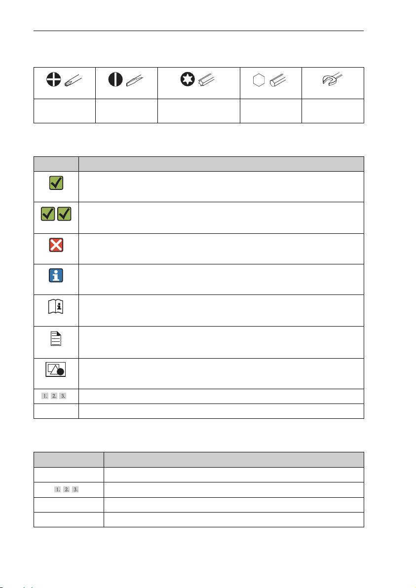
1.1 Document conventions ........................................................... 3
2 Basic safety instructions ................................................... 6
2.1 Requirements for the personnel .................................................... 6
2.2 Designated use ................................................................. 6
2.3 Workplace safety ............................................................... 7
2.4 Operational safety .............................................................. 7
2.5 Product safety ................................................................. 7
3 Product description ........................................................ 8
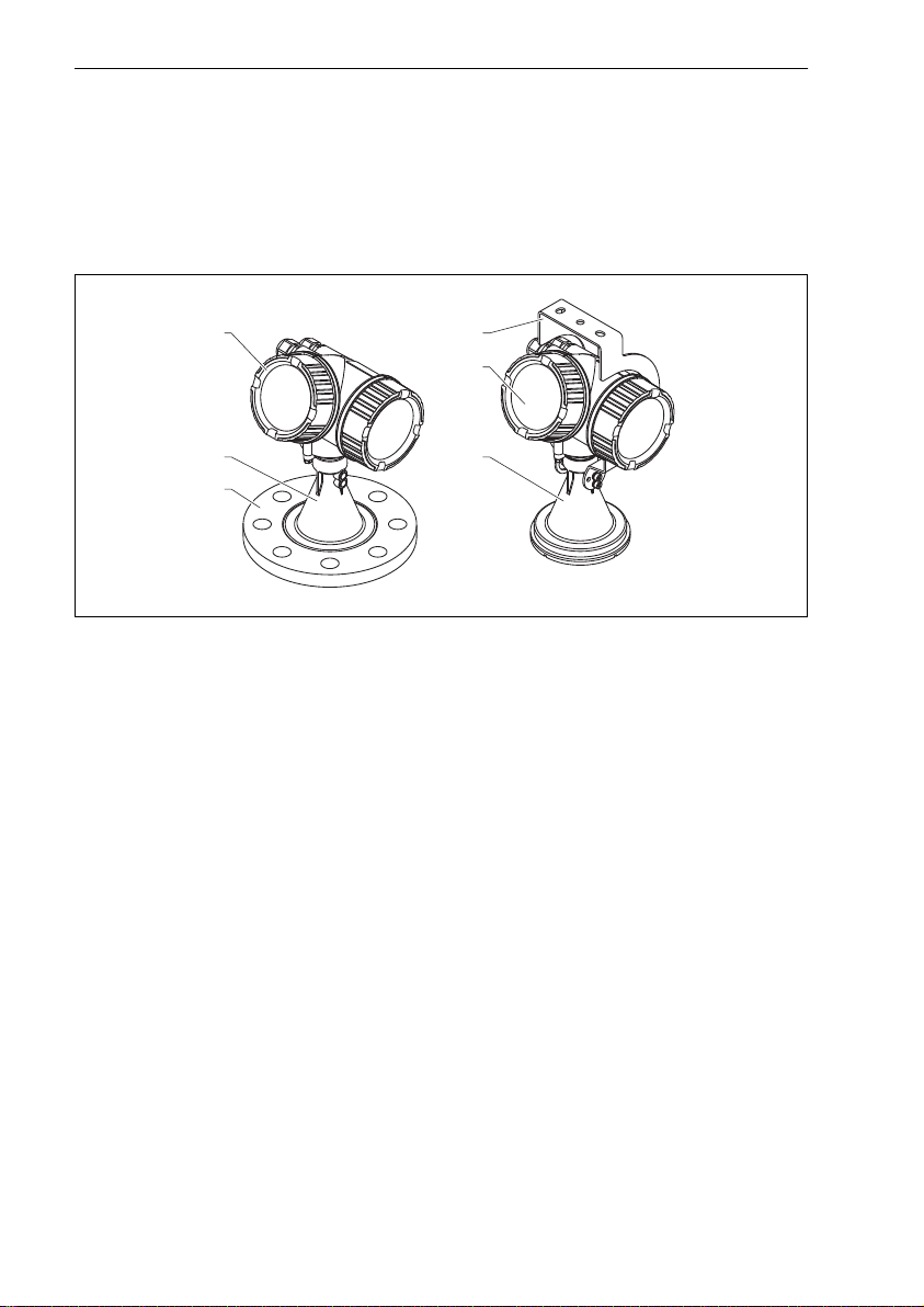
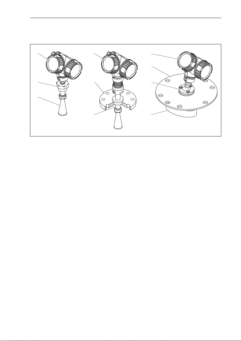
3.1 Product design ................................................................. 8
4 Incoming acceptance and product identification .......................... 11
4.1 Incoming acceptance ........................................................... 11
4.2 Product identification ........................................................... 13
5 Storage, Transport ....................................................... 14
5.1 Storage conditions ............................................................. 14
5.2 Transport product to the measuring point ............................................ 14
6 Installation ............................................................... 15
6.1 Installation conditions .......................................................... 15
6.2 Measuring conditions ........................................................... 22
6.3 Installation in vessel (free space) ................................................... 24
6.4 Vessels with heat insulation ...................................................... 35
6.5 Turning the transmitter housing ................................................... 35
6.6 Turning the display module ....................................................... 36
6.7 Post-installation check .......................................................... 36
7 Electrical connection ..................................................... 38
7.1 Connection conditions .......................................................... 38
7.2 Connecting the measuring device .................................................. 44
7.3 Post-connection check .......................................................... 47
8 Integration into a FOUNDATION Fieldbus network ....................... 47
8.1 Device Description (DD) ......................................................... 47
8.2 Integration into the FOUNDATION Fieldbus network .................................... 48
8.3 Device identification and addressing ................................................ 48
8.4 Block model .................................................................. 50
8.5 Assignment of the measured values (CHANNEL) in an AI Block ............................ 51
8.6 Methods ..................................................................... 53
9 Commissioning (via operating menu) .................................... 54
9.1 Display and operating module ..................................................... 54
9.2 Operating menu ............................................................... 56
9.3 Unlock the device .............................................................. 57
9.4 Setting the operating language .................................................... 57
9.5 Configuration of a level measurement ............................................... 58
9.6 User-specific applications ........................................................ 60
10 Commissioning (block-based operation) .................................. 60
10.1 Block configuration ............................................................. 60
10.2 Scaling of the measured value in an AI Block .......................................... 62
10.3 Language selection ............................................................. 63
10.4 Configuration of a level measurement ............................................... 64

Micropilot FMR56, FMR57 FOUNDATION Fieldbus Important document information
Endress+Hauser 3
10.5 Configuration of the on-site display ................................................. 67
10.6 Configuration management ...................................................... 67
1 Important document information
1.1 Document conventions
1.1.1 Safety symbols
Symbol Meaning
DANGER
A0011189-EN
DANGER!
This symbol alerts you to a dangerous situation. Failure to avoid this situation will
result in serious or fatal injury.
WARNING
A0011190-EN
WARNING!
This symbol alerts you to a dangerous situation. Failure to avoid this situation can
result in serious or fatal injury.
CAUTION
A0011191-EN
CAUTION!
This symbol alerts you to a dangerous situation. Failure to avoid this situation can
result in minor or medium injury.
NOTICE
A0011192-EN
NOTICE!
This symbol contains information on procedures and other facts which do not result in
personal injury.
1.1.2 Electrical symbols
Symbol Meaning
A0011197
Direct current
A terminal to which DC voltage is applied or through which direct current flows.
A0011198
Alternating current
A terminal to which alternating voltage is applied or through which alternating current flows.
A0017381
Direct current and alternating current
• A terminal to which alternating voltage or DC voltage is applied.
• A terminal through which alternating current or direct current flows.
A0011200
Ground connection
A grounded terminal which, as far as the operator is concerned, is grounded via a grounding
system.
A0011199
Protective ground connection
A terminal which must be connected to ground prior to establishing any other connections.
A0011201
Equipotential connection
A connection that has to be connected to the plant grounding system: This may be a potential
equalization line or a star grounding system depending on national or company codes of
practice.

Important document information Micropilot FMR56, FMR57 FOUNDATION Fieldbus
4 Endress+Hauser
1.1.3 Tool symbols
A0011219 A0011220 A0013442 A0011221 A0011222
Cross-head
screwdriver
Flat blade
screwdriver Torx screwdriver Allen key Hexagon wrench
1.1.4 Symbols for certain types of information
Symbol Meaning
A0011182
Allowed
Indicates procedures, processes or actions that are allowed.
A0011183
Preferred
Indicates procedures, processes or actions that are preferred.
A0011184
Forbidden
Indicates procedures, processes or actions that are forbidden.
A0011193
Tip
Indicates additional information.
A0011194
Reference to documentation
Refers to the corresponding device documentation.
A0011195
Reference to page
Refers to the corresponding page number.
A0011196
Reference to graphic
Refers to the corresponding graphic number and page number.
,…
,
Series of steps
Result of a sequence of actions
1.1.5 Symbols in graphics
Symbol Meaning
1, 2, 3 ... Item numbers
,…
,
Series of steps
A, B, C, ... Views
A-A, B-B, C-C, ... Sections

Micropilot FMR56, FMR57 FOUNDATION Fieldbus Important document information
Endress+Hauser 5
Symbol Meaning
-
A0011187
Hazardous area
Indicates a hazardous area.
.
A0011188
Safe area (non-hazardous area)
Indicates a non-hazardous location.
1.1.6 Symbols at the device
Symbol Meaning
Safety instructions
Observe the safety instructions contained in the associated Operating Instructions.
Temperature resistance of the connection cables
Specifies the minimum value of the temperature resistance of the connection cables.

Basic safety instructions Micropilot FMR56, FMR57 FOUNDATION Fieldbus
6 Endress+Hauser
2 Basic safety instructions
2.1 Requirements for the personnel
The personnel must fulfill the following requirements for its tasks:
‣Trained, qualified specialists must have a relevant qualification for this specific
function and task
‣Are authorized by the plant owner/operator
‣Are familiar with federal/national regulations
‣Before beginning work, the specialist staff must have read and understood the
instructions in the Operating Instructions and supplementary documentation as well
as in the certificates (depending on the application)
‣Following instructions and basic conditions
2.2 Designated use
Application and measured materials
The measuring device described in these Operating Instructions is intended for the
continuous, contactless level measurement of mainly bulk solids. The device can also be
freely mounted outside closed metal vessels because of its operating frequency of about
26 GHz, a maximum radiated pulsed power of 23.3 mW and an average power output
of 0.076 mW. Operation is completely harmless to humans and animals.
Observing the limit values specified in the "Technical data" and listed in the Operating
Instructions and supplementary documentation, the measuring device may be used for
the following measurements only:
‣Measured process variables: level, distance, signal strength
‣Calculated process variables: Volume or mass in arbitrarily shaped vessels; flow
through measuring weirs or flumes (calculated from the level by the linearization
functionality)
To ensure that the measuring device remains in proper condition for the operation
time:
‣Use the measuring device only for measured materials against which the process-
wetted materials are adequately resistant.
‣Observe the limit values in "Technical data".
Incorrect use
The manufacturer is not liable for damage caused by improper or non-designated use.
Verification for borderline cases:
‣For special measured materials and cleaning agents, Endress+Hauser is glad to
provide assistance in verifying the corrosion resistance of wetted materials, but does
not accept any warranty or liability.
Residual risk
The electronics housing and its built-in components such as display module, main
electronics module and I/O electronics module may heat to 80 °C (176 °F) during
operation through heat transfer from the process as well as power dissipation within

Micropilot FMR56, FMR57 FOUNDATION Fieldbus Basic safety instructions
Endress+Hauser 7
the electronics. During operation the sensor may assume a temperature near the
temperature of the measured material.
Danger of burns due to heated surfaces!
‣For high process temperatures: Install protection against contact in order to prevent
burns.
2.3 Workplace safety
For work on and with the device:
‣Wear the required personal protective equipment according to federal/national
regulations.
2.4 Operational safety
Risk of injury.
‣Operate the device in proper technical condition and fail-safe condition only.
‣The operator is responsible for interference-free operation of the device.
Conversions to the device
Unauthorized modifications to the device are not permitted and can lead to
unforeseeable dangers.
‣If, despite this, modifications are required, consult with the manufacturer.
Repair
To ensure continued operational safety and reliability,
‣Carry out repairs on the device only if they are expressly permitted.
‣Observe federal/national regulations pertaining to repair of an electrical device.
‣Use original spare parts and accessories from the manufacturer only.
Hazardous area
To eliminate a danger for persons or for the facility when the device is used in the
hazardous area (e.g. explosion protection, pressure vessel safety):
‣Based on the nameplate, check whether the ordered device is permitted for the
intended use in the hazardous area.
‣Observe the specifications in the separate supplementary documentation that is an
integral part of these Instructions.
2.5 Product safety
This measuring device is designed in accordance with good engineering practice to
meet state-of-the-art safety requirements, has been tested, and left the factory in a
condition in which they are safe to operate.
It meets general safety standards and legal requirements. It also complies with the EC
directives listed in the device-specific EC Declaration of Conformity. Endress+Hauser
confirms this by affixing the CE mark to the device.

Product description Micropilot FMR56, FMR57 FOUNDATION Fieldbus
8 Endress+Hauser
3 Product description
3.1 Product design
3.1.1 Micropilot FMR56
1 4
1
22
3
A0016791
1 Design of the Micropilot FMR56 (26 GHz)
1 Electronics housing
2 Horn 80mm/100 mm (3in/4in), PP cladded
3 Flange
4 Mounting bracket

Micropilot FMR56, FMR57 FOUNDATION Fieldbus Product description
Endress+Hauser 9
3.1.2 Micropilot FMR57
1
2 4
4
6
3
5 7
1 1
A0016807
2 Design of the Micropilot FMR57 (26 GHz)
1 Electronics housing
2 Process connection (Thread)
3 Horn antenna
4 Flange
5 Antenna extension
6 Alignment device
7 Parabolic antenna

Product description Micropilot FMR56, FMR57 FOUNDATION Fieldbus
10 Endress+Hauser
3.1.3 Electronics housing
Esc
–+E
123
4
5
6
9
7
8
A0012422
3 Design of the electronics housing
1 Electronics compartment cover
2 Display module
3 Main electronics module
4 Cable glands (1 or 2, depending on instrument version)
5 Nameplate
6 I/O electronics module
7 Terminals (pluggable spring terminals)
8 Connection compartment cover
9 Grounding terminal

Micropilot FMR56, FMR57 FOUNDATION Fieldbus Incoming acceptance and product identification
Endress+Hauser 11
4 Incoming acceptance and product identification
4.1 Incoming acceptance
A0013696
DELIVERY NOTE
1 = 2
A0016870
A0016871
A0013696
A0016872

Incoming acceptance and product identification Micropilot FMR56, FMR57 FOUNDATION Fieldbus
12 Endress+Hauser
A0013696
DELIVERY NOTE
Made in Germany, 79689 Maulburg
A0014038
A0013696
A0014037
If one of the conditions does not comply, contact your Endress+Hauser distributor.

Micropilot FMR56, FMR57 FOUNDATION Fieldbus Incoming acceptance and product identification
Endress+Hauser 13
4.2 Product identification
The following options are available for identification of the measuring device:
• Nameplate specifications
• Extended order code with breakdown of the device features on the delivery note
• Enter serial numbers from nameplates in W@M Device Viewer
( www.endress.com/deviceviewer ): All information about the measuring device is
displayed.
For an overview of the scope of the Technical Documentation provided, refer to the
following: enter serial numbers from nameplates in W@M Device Viewer
( www.endress.com/deviceviewer )
4.2.1 Nameplate
Order code:
Ext. ord. cd.:
Ser. no.:
1
2
3
A0014103
4 Example of a nameplate
1 Order code
2 Serial number (Ser. no.)
3 Extended order code (Ext. ord. cd.)
For detailed information about interpreting the nameplate specifications, refer to
the Operating Instructions for the device on the CD-ROM provided.
Only 33 digits of the extended order code can be indicated on the nameplate. If
the extended order code exceeds 33 digits, the rest will not be shown. However,
the complete extended order code can be viewed in the operating menu of the
device (Diagnostics → Device info → Extended order code 1/2/3).

Storage, Transport Micropilot FMR56, FMR57 FOUNDATION Fieldbus
14 Endress+Hauser
5 Storage, Transport
5.1 Storage conditions
• Permitted storage temperature: –40 to +80 °C (–40 to +176 °F)
• Use the original packaging.
5.2 Transport product to the measuring point
NOTICE
Housing or antenna horn may be damaged or break away.
Risk of injury!
‣Transport the measuring device to the measuring point in its original packaging or
at the process connection.
‣Do not fasten lifting devices (hoisting slings, lifting eyes etc.) at the housing or the
antenna horn but at the process connection. Take into account the mass center of
the device in order to avoid unintended tilting.
‣Comply with the safety instructions, transport conditions for devices over 18kg
(39.6lbs).
A0016875

Micropilot FMR56, FMR57 FOUNDATION Fieldbus Installation
Endress+Hauser 15
6 Installation
6.1 Installation conditions
6.1.1 Mounting position
A
1 2 3
A0016883
• Recommended distance A from
wall to outer edge of nozzle: ~
1/6 of vessel diameter.
Nevertheless the device should
not be installed closer than
20 cm (7.87 in) to the vessel
wall.
If the wall of the vessel is not
smooth (corrugated metal,
welding seams, irregularities
etc.) the distance from the wall
should be kept as large as
possible. If necessary, use an
alignment device to prevent
interference reflections from
the wall (→ 33).
• Not in the center (2), as
interference can cause signal
loss.
• Not above the fill stream (3).
• It is recommended to us a
weather protection cover (1) in
order to protect the device from
direct sun or rain.
• In extremely dusty applications,
the integrated air purge
connection can prevent
clogging of the antenna
(→ 34).

Micropilot FMR56, FMR57 FOUNDATION Fieldbus Installation
Endress+Hauser 17
6.1.3 Reduction of interference echoes
a
b
A0016889
Metallic screens mounted at a
slope spread the radar signal and
can, therefore, reduce
interference echoes.
6.1.4 Measurement in a plastic vessel
If the outer wall of the vessel is made of a non-conductive material (e.g. GRP),
microwaves can also be reflected off interfering installations outside the signal beam
(e.g. metallic pipes (1), ladders (2), grates (3), ...). Therefore, there should be no such
interfering installations in the signal beam. Please contact Endress+Hauser for further
information.

Installation Micropilot FMR56, FMR57 FOUNDATION Fieldbus
18 Endress+Hauser
2
3
1
A0017125

Micropilot FMR56, FMR57 FOUNDATION Fieldbus Installation
Endress+Hauser 19
6.1.5 Optimization options
• Antenna size
The bigger the antenna, the smaller the beam angle α and the fewer interference
echoes (→ 20).
• Mapping
The measurement can be optimized by means of electronic suppression of
interference echoes.
• Antenna alignment
Take into account the marker on the flange or threaded connection (→ 24).
• Metallic screens mounted at a slope
They spread the radar signals and can, therefore, reduce interference echoes.
• Variable flange seal (FMR56)
Using the variable flange seal, the device can be aligned in the direction of the
product surface. For details refer to Operating Instructions BA01048F, chapter
"Accessories".
• Alignment device for FMR57
In FMR57 with alignment device, the sensor can be optimally aimed within the
vessel and thus interference echoes can be avoided. The maximum angle β is ±15°.
In particular, sensor alignment serves to:
– prevent interference reflections
– extend the maximum possible measuring range in conical outlets

Installation Micropilot FMR56, FMR57 FOUNDATION Fieldbus
20 Endress+Hauser
6.1.6 Beam angle
a
D
W
a
D
_
=2
2. . tan
W
A0016891
5 Relationship between beam angle α, distance D and beamwidth diameter W
The beam angle is defined as the angle α where the energy density of the radar waves
reaches half the value of the maximum energy density (3-dB-width). Microwaves are
also emitted outside the signal beam and can be reflected off interfering installations.
Beam diameter W as a function of beam angle α and measuring distance D:
FMR56
Antenna size 80 mm (3 in) 100 mm (4 in)
Beam angle α 10° 8°
Measuring distance (D) Beamwidth diameter (W)
3 m (9.8 ft) 0.53 m (1.7 ft) 0.42 m (1.4 ft)
6 m (20 ft) 1.05 m (3.4 ft) 0.84 m (2.8 ft)
9 m (30 ft) 1.58 m (5.2 ft) 1.26 m (4.1 ft)
12 m (39 ft) 2.1 m (6.9 ft) 1.68 m (5.5 ft)
15 m (49 ft) 2.63 m (8.6 ft) 2.10 m (6.9 ft)
20 m (66 ft) 3.50 m (11 ft) 2.80 m (9.2 ft)
25 m (82 ft) 4.37 m (14 ft) 3.50 m (11 ft)
30 m (98 ft) 5.25 m (17 ft) 4.20 m (14 ft)
FMR57 - Horn antenna
Antenna size 80 mm (3 in) 100 mm (4 in)
Other manuals for Micropilot FMR56
8
This manual suits for next models
1
Table of contents