Ashton MXL12FX User manual

MXL12FX
12 CHANNEL MIXER WITH DIGITAL FX
USER MANUAL
MX12FX_MANUAL.indd 1 8/07/10 5:20 PM

MX12FX_MANUAL.indd 2 8/07/10 5:20 PM

PAGE 1
Contents
INTRODUCTION...................................................2
MXL12FXSPECIFICATIONS........................................2
UNDERSTANDINGMIXERS ........................................3
SECTIONPAGEBREAKDOWN......................................4
MAINCONTROLS .................................................5
DIGITALEFFECTSPROCESSOR.....................................6
MONOCHANNELS1-4.............................................8
STEREOCHANNELS5-12..........................................9
REARPANEL.....................................................10
POWER..........................................................10
SETUPEXAMPLE.................................................11
HEADPHONEPLUGS..............................................12
SAFETYINFORMATION...........................................13
NOTES ..........................................................14
MX12FX_MANUAL.indd 1 8/07/10 5:20 PM

PAGE 2
IntRoDUCtIon
Ashton is designed in Australia by a team of industry experts that have years of experience
in the development, design and production of musical instruments and equipment. Ashton’s
range of amps are a result of years of development and careful testing. Every Ashton
product is designed with value in mind and features the highest quality materials available.
This manual will help you understand some of the great features of your mixer.
Enjoy,
The Ashton Team
MXL12FX sPeCIFICAtIons
•4monomic/linechannels&2stereochannels
•130dBdynamicrange
•Lownoise,distortionfreecircuitry,naturalandtransparentsignalreproduction
•3-bandEQ(channel1-4)
•PostfaderFXsendperchannel
•Built-indigitalmulti-effectprocessorwith100effectsincludingreverb,delayand
modulation effects.
•Phantompower+48V
•CD/Tapeinputstomainmixorcontrolroom&headphoneoutput
•Dimensions:260×240×37.5mm
•Weight:1.7Kg
•Powersupply:20W
MX12FX_MANUAL.indd 2 8/07/10 5:20 PM

PAGE 3
UnDeRstAnDInG MIXeRs
A mixer allows input signals to be manipulated through various stages until the signal
issentbackout.Thestagesareasfollows:
Signal Processing
•Adjustingtheleveloftheinputsignal.
•Equalizingthebass,middleandtreblefrequenciesoftheinputtedsignal.
•Addingofeffects(suchasreverb,chorusetc)tothesignal.
Mixing
•Adjustingthelevelsoftheindividualchannel.
•Positioningthesignalinthestereofield(LorR)byusingthepanfunction.
•Assigningoftrackstooutputs.
Outputs
•Thisiswheredevicessuchasrecordersandspeakerscanbepluggedin.
NOTE: Alwaysmakesurethatalllevelsettingsaresettozerowhenpoweringon
andconnectingdevices.Thiswillavoiddamagetospeakersandunits.Werecommend
taking note of your settings so that it is easy to reset them every time you power on the
unit.Wehaveprovidedanotessectionattheendofthismanualforthis.
MX12FX_MANUAL.indd 3 8/07/10 5:20 PM
PAGE 4
seCtIon PAGe BReAKDoWn
PAGE 5
PAGE 5
PAGE 8 PAGE 9
PAGE 6
PAGE 10
MX12FX_MANUAL.indd 4 8/07/10 5:20 PM

PAGE 5
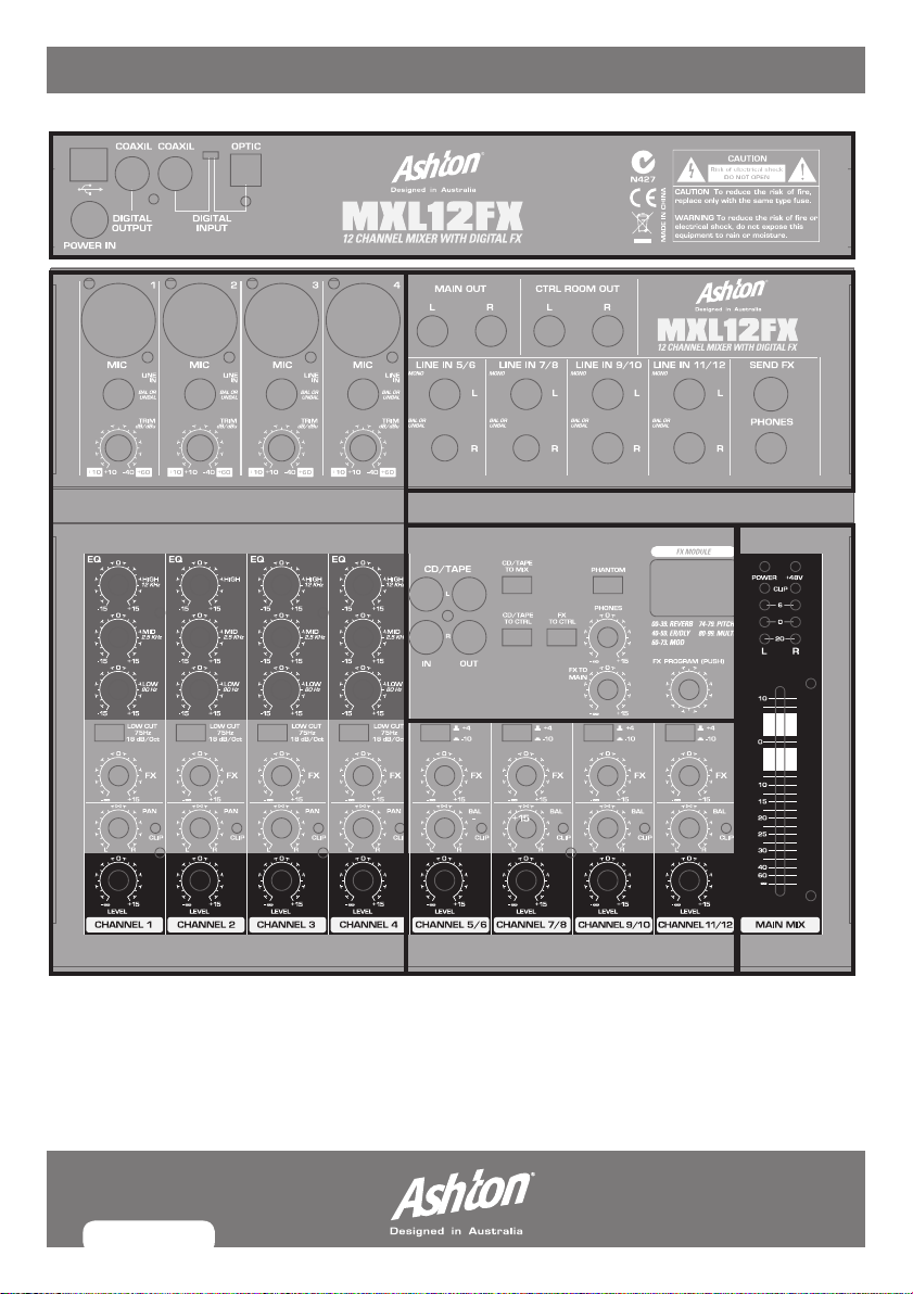
MAIn ContRoLs
1. MAIN OUT: ¼"Stereomainoutput(outputsmixersignals).
2. CTRL ROOM OUT: ¼"Stereomainoutput(outputsmixersignals).
3. FX SEND: This outputs the fx signal. You can connect this to the input
ofanexternaleffectsdeviceinordertoprocesstheFXbussignal.
Once an effects mix is created, the processed signal can then be
routed from the effects devices outputs back into a stereo input.
4. PHONES: This is where you connect your headphones.
5. POWER: Indicated that the console is powered on.
6. +48V: Indicates that the phantom power is on.
7.LEVEL INDICATOR: Displaystherelevantsignallevel.
8. MAIN MIX FADER: Adjusts the level of the entire mix which is then
sent to the main out jacks.
MX12FX_MANUAL.indd 5 8/07/10 5:20 PM
PAGE 6
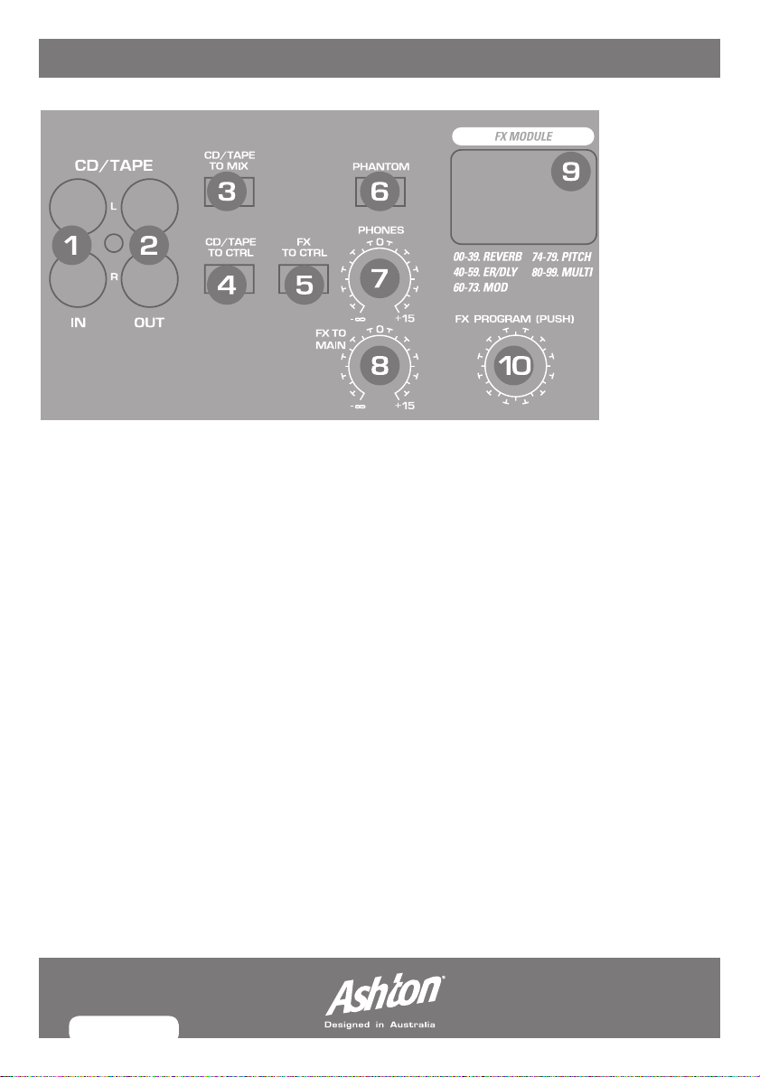
DIGItAL eFFeCts PRoCessoR
Thebuilt-indigitalstereoeffectsprocessoroffersalargenumberofstandardeffectssuch
asHall,Chorus,Flanger,Delayandvariouscombinationeffects.UsingtheFXcontrol,you
can feed signals into the effects processor.
1. CD/TAPE IN:RCAjackinputforexternalsignalsource(cd/tapeconnection)intomixer.
2. CD/TAPE OUT:FormixersoundoutputviaRCAjack.Connecttheinputsofacomputer
sound card or recorder here.
3. CD/TAPE TO MIX: WhentheTAPETOMIXbuttonispressed,the2-trackinput
isassignedtothemainmixprovidinganadditionalinputfortapemachines,MIDI
instruments or other signal sources that do not require any processing.
4. CD/TAPE TO CTRL:Presstomonitorthe2-trackinputviatheCTRLROOMOUT
outputs. This provides an easy way to monitor signals coming back from an external
source to ensure they are recording correctly.
5. FX TO CNTRL:EngagethisinordertomonitortheFXsignalthroughyourheadphones
or monitor speakers.
6. PHANTOM POWER:Thisengages/disengagesphantompowerformixercompatibility
withcondensermicrophonesanddevicesthatrequirephantompower.WhenPhantom
powerisengaged,theLEDwillbelit.
MX12FX_MANUAL.indd 6 8/07/10 5:20 PM

PAGE 7
DIGItAL eFFeCts PRoCessoR
Note:NeveruseunbalancedXLRconnectors(PIN1to3connected)ontheMICinput
connectorswhenusingphantompowersupply.Connectmicsandmutemonitor/PA
loudspeakersBEFOREswitchingonphantompowersupply.
7. PHONES: This adjusts the levels of the headphones.
8. FX TO MAIN: This feeds the effects signal into the main mix. If the control is turned all
thewaycounter-clockwise,noeffectssignalispresentinthesignalofthemixingconsole.
9. CLIP/SIGNAL LED: IfthisLEDisconstantlyon,itmeansthattheeffectsprocessoris
overdriven which results in distortion.
10. FX PROGRAM: Turn the program control to dial in an fx program number program
number. The number of the preset dialed in will blink in the display. To confirm
selection, press the program control and the blinking will stop.
MX12FX_MANUAL.indd 7 8/07/10 5:20 PM

PAGE 8
Mono CHAnneLs 1-4
1. MIC: BalancedmicrophoneinputviatheXLRconnector.
2. LINE IN: Balancedlineinputona¼"connector.Unbalanceddevices
(monojacks)canalsobeconnectedtotheseinputs.
You should not use the microphone and the line input of a channel
simultaneously.
3. TRIM: This adjusts the input gain. This control should always be turned
fullycounter-clockwisewheneveryouconnectordisconnectasignal
sourcetooneoftheinputs.Firstvaluerange(+10to+60)showsMIC
inputsignals,secondvaluerange(+10to+60)referstothelineinput.
4. EQ: HIGH:Thisadjuststhehighfrequencies(-15dBto+15dB)ofthe
inputtedsignal.Whensetto0,thefrequencyisunaffected.
5.EQ: MID:Thisadjuststhemiddlefrequencies(-15dBto+15dB)ofthe
inputtedsignal.Whensetto0,thefrequencyisunaffected.
6.EQ: LOW:Thisadjuststhelowfrequencies(-15dBto+15dB)ofthe
inputtedsignal.Whensetto0,thefrequencyisunaffected.
7. LOW CUT: Thiseliminatesunwantedlow-frequencysignals.
8. FX: This adjusts the fx level that is sent to the internal fx and also the
“send fx” jack.
9. PAN: This determines the position of channel signal within the stereo
image and how it is distributed to the left and right speakers.
10. CLIP:ThisLEDilluminateswhentheinpputsignalistoohighwhich
cancausedistortion.Usetrimcontroltoreducethelevel.
11. LEVEL:Thisdeterminesthelevel(volume)ofthechannelsignalin
the main mix.
1
2
3
4
5
6
7
MX12FX_MANUAL.indd 8 8/07/10 5:20 PM
Table of contents


