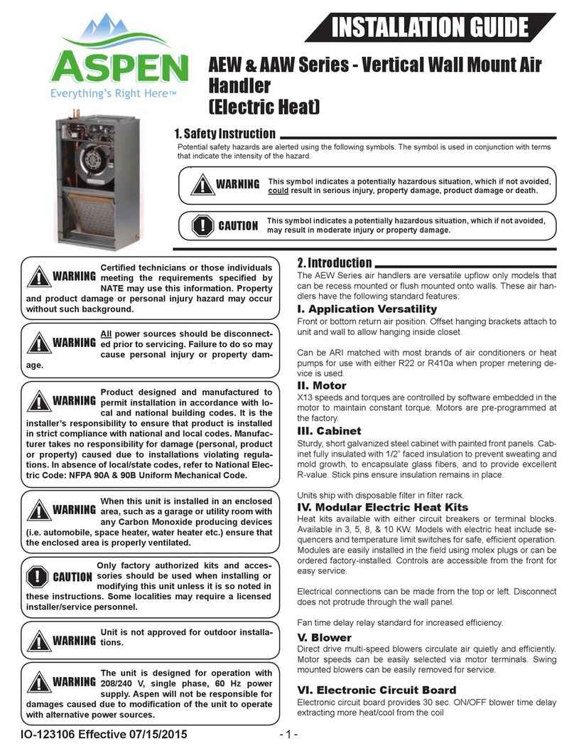
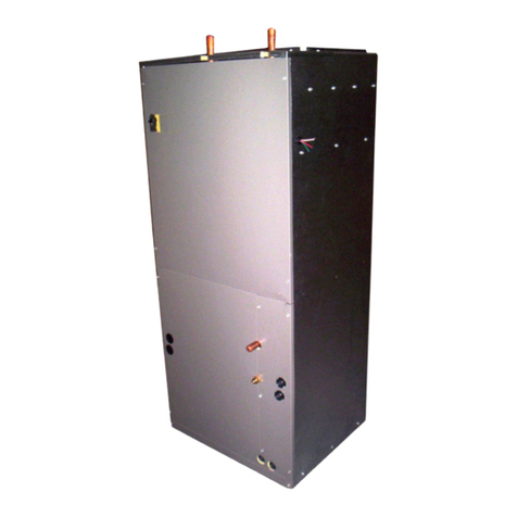
Aspen FWB SERIES User manual

123013 9/6/05
INSTALLATION INSTRUCTION
FWB SERIES HYDRONIC VERTICAL WALL MOUNT AIR
HANDLER
IMPORTANT MASSAGE TO INSTALLER: "The United States Environmental Protection Agency ("EPA") has issued
various regulations regarding the introduction of disposal of refrigerants in this unit. Failure to follow these regulations
may harm the environment and can lead to the imposition of substantial fines. Because these regulations may vary
due to the passage of new laws we suggest that any work on this unit be done by a certified technician. Should you
have any questions please contact the local office of EPA." Some Aspen coils may include a Schrader valve on the
suction manifold. During installation, this Schrader valve must be protected from heat or it may leak.
All Aspen coils are shipped with a nitrogen holding charge. DO NOT install the coil if this charge is not present.
IMPORTANT MESSAGE TO OWNER: These instructions should be carefully read and kept near product, for future
reference. While these instructions are addressed primarily to the installer, useful maintenance information is included.
Have your installing dealer acquaint you with the operating characteristics of the product and periodic homeowner
maintenance requirements. As expressed in our product warranty, Aspen will not be billed for any structural damage
due to failure to follow these installation requirements. Once installed, Aspen coils may contain chlorofluorocarbons
(CFC's) or hydrochlorofluorocarbons (HCFC's). Under certain conditions, CFC's & HCFC's may pose a health risk.
Please notify a licensed service technician immediately if you suspect your system may contain a leak.
CODES AND REGULATIONS
This product is designed and manufactured to permit installation in accordance with National Codes. It is the installer’s
responsibility to install the product in accordance with National Codes and/or prevailing local codes and regulations.
The manufacturer assumes no responsibility for equipment installed in violation of any code or regulation.
INSPECTION
This product has been inspected and run tested at the factory and released to the transportation agency without known
damage. Inspect exterior of carton for evidence of rough handling in shipment. Unpack carefully, if damage is found,
report immediately to the transportation agency.
REPLACEMENT PARTS
Order all replacement parts through your local distributor. When ordering parts, give complete model and serial
number as shown on the unit rating plate.

123013 9/6/05
2
INSTALLATION NOTES
• This unit must be installed in accordance with all local
and national codes.
• If screws or holes must be drilled into fan coil cabinet,
check carefully to insure that no damage is done to
internal components.
• Use a low temperature, NON-LEAD solder on all
water line copper joints.
• Insulate all water piping as necessary to prevent
freezing.
WARNING!
If a back flow preventer is installed in the system, an
expansion tank is necessary.
WARNING!
The hot water coil and all water lines must be purged
of air before the hot water pump can be energized.
Failure to purge the water system of air can result in
damage to the pump.
UNIT INSTALLATION
This unit must be installed in a vertical position with the
return at the bottom and the plenum at the top. The
return may be ducted through the bottom of the unit by
removing the drain access panel and filter, then
reattaching the lower access panel. The clearance to
combustibles (which includes the cabinet, plenum, and
all connecting duct work) is zero inches. However,
approximately 20 inches of clearance must be provided
at the front of the unit to allow access to internal
components. Several installations are possible in this
configuration:
• The bracket can be hung on a closet wall by using the
factory supplied bracket. To prevent the transfer of
normal operational sound through the wall, use a
sound deadening or isolating material.
• The unit can be installed on a platform in a closet.
Screws or nails must be used to secure the unit in
place. The platform must provide ample clearance for
drain lines that exit the unit from the bottom.
• The fan coil can be installed in a partition wall as
shown in Figure 1. A louvered wall panel or perforated
door (made by the coil manufacturer) must be used
with this type of installation. The fan coil is installed
before the drywall and louvered panel is installed with
screws or nails once the drywall is in place.
AIR DUCT INSTALLATION NOTES
If a ducted return is used, it must have the same free
area as the opening on the unit. If a non-ducted return
is used, local or national codes may restrict the unit
installation to single story residences only.
ELECTRICAL WIRING
All information needed to connect the 120VAC supply
and 24VAC control wiring is supplied with the unit (see
Figure 2). Two knockouts are located at the top of the
unit for connection of power and control wiring. Since
this unit is supplied with a 24 volt Class 2 transformer,
a thermostat with isolating contacts must be used
when connecting other add-on equipment using a
Class 2 transformer.
EVAPORATOR COIL CONNECTIONS
This fan coil uses a factory installed fixed orifice piston
to meter the refrigerant for the evaporator coil. This
allows the fan coil to be matched with either a heat
pump or a standard condensing unit. The size of the
suction and liquid refrigerant lines is determined by the
instructions supplied with the outdoor unit. The
evaporator coil has a nitrogen charge from the factory
and must be dumped before being connected. The
connections for both the liquid refrigerant and the
suction lines are sweated connections.

123013 9/6/05
3
CONDENSATE DRAIN CONNECTIONS
A minimum trap of 1-1/2" must be in the drain line so
that there is proper drainage. The drain lines must be
installed to slope away from the fan coil. These units
are equipped with a bottom primary and secondary
drain and a single side primary or secondary. When
utilizing a unit disable switch on the secondary line, it
must be located on the side connection to avoid a false
shutdown created by condensate droplets falling into
the bottom secondary connection. It should be
adjusted to permit normal operation of the unit and
disable the unit in the event of a clogged primary
before the condensate spills over the pan. In lieu of
this, a hood may be field fabricated to slide over the
secondary to keep droplets out but allow trapped
condensate into the secondary fitting.
HOT WATER CONNECTIONS
The connections to the hot water coil are 3/4" (7/8"OD)
copper tubing. The hot water inlet is located on the top
right of the unit (a label on the unit clearly identifies the
correct connection). All piping connecting the fan coil to
the house water system should be 3/4" (7/8"OD)
copper tubing or 3/4" nominal CPVC with appropriate
CPVC to copper fittings. This size tubing will prevent
loss of head pressure. The total length of piping used
to connect the fan coil to the water heater should not
exceed 200 feet for 3/4" nominal copper and 120 feet
for 3/4" nominal CPVC. Use "T" fittings at the water
heater to connect into the house water system. These
"T" fittings must be installed on the vertical hot and
cold supply lines of the water heater shown in Figure 3.
The connections from the fan coil unit are made to the
horizontal connections of the "T" fittings. This will allow
air to be purged from the system when water is used in
the home. Between the fan coil and water heater
connections, two valves (provided by the installer)
must be installed to permit purging of air in the system
and also to allow the hot water coil in the unit to be
separated from the house water system during
servicing.
PURGING THE SYSTEM
1. Open air vent and allow water heater to fill with
water. Close air vent when water heater is full and all
air has been purged.
2. Ignite water heater. Set thermostat on water heater
to 140 degrees.
DANGER!
140-degree water can cause first-degree burns. We
strongly recommend the installation of a water-
tempering valve (for water temperatures above 140-
degrees) to supply lower temperature water to the
fixtures in the house. Use Watts N170L series or
equivalent.
1. Close the valve on the hot water supply from the
water heater ("A") and open the valve on the cold-
water return then the water heater ("B"). Then open the
air vent in the fan coil. Use bucket or hose to discard
water during purging process at air bleed valve. Purge
air completely from lines.
2. Once air is purged, close return valve ("B") and open
supply valve ("A"). Purge the coil and lines of air
completely.
3. After air is purged from the system and filled with
water, open the return valve ("B") and the supply valve
("A"). Then close the air vent in the fan coil.
4. Apply power to the fan coil and set the room
thermostat on heat. Raise the temperature setting to
activate the circulating pump.
5. Check the pump to insure proper operation. The
water inlet of the unit should be hot if the water
temperature in the water heater has reached the set
point. If water is not being circulated through the coil
but the pump is running, then open the air bleed valve
in the unit and purge any air left in the system.
6. Adjust the water heater thermostat so that the water
temperature entering the hot water coil is 120 to 180
degrees depending on the amount of heat required by
the structure. This is done with the unit energized and
operating long enough for all temperatures to stabilize.

123013 9/6/05
4
AIR FILTER REPLACEMENT
An air filter can restrict the airflow of air to the fan coil if
it is not cleaned or replaced periodically. When
replacing the air filter, always replace with the same
type and size as originally furnished with the unit.
PUMP REPLACEMENT
1. Disconnect electrical power to the unit before
servicing.
2. Remove access door to reveal pump. Close supply
valve ("A") and return valve ("B"). Open the air bleed
valve to de-pressurize the system and drain water.
3. Remove the metal pump housing by loosening the
four screws on the pump. DO NOT UN-SOLDER
PUMP.
4. Replace the new pump housing assembly and
reconnect components to the pump. Before
assembling, make sure that the rubber on the o-ring is
in place on the pump housing.
Purge the system of air as described earlier and
reconnect the electrical power.
COMMON PROBLEMS & SOLUTIONS
•NOISY PUMP:
System may not be totally purged of air. Purge the
system again as described earlier.
•T & P VALVE ON WATER HEATER WEEPS:
This normally occurs when a backflow preventer has
been installed in the cold water line supplying the water
heater. An expansion tank may be necessary to correct
the problem. Contact a qualified plumbing professional
for assistance.
•HOT WATER IS CIRCULATING THROUGH THE
HEATING COIL DURING THE COOLING CYCLE:
The check valve may be stuck open and allowing hot
water to circulate through the coil.
•LITTLE OR NO HEAT FROM WATER COIL:
A. Purge the system.
B. The inlet and outlet connections may be reversed at
the fan coil.
C. Water heater thermostat is not set at proper
temperature.
D. Water heater thermostat is not calibrated.
E. The dip tube in the water heater may not be
installed correctly or may be restricted.
F. Look for restriction in heating system from water
heater to fan coil. Because some water heaters are
supplied with check valves, remove any extra check
valves except for the one supplied with the fan coil.
G. The air handler is undersized for the space being
heated.
H. Water heater is undersized.

123013 9/6/05
5
Equipment Sizing
Air Handler Selection:
Select an air handler with a heating output that exceeds the space heating loss of the structure and that has a cooling
coil sized to match the outdoor condensing unit. Special note… the heating output of the air handler or hot water coil
will not be greater than the output of the selected hot water heater. Therefore, if the water heater is undersized the
heating BTUH of the air handler will be LESS than it's rated output.
Water Heater Selection:
The following sizing information should only be used as a basic guide to adequate water heater sizing because of
variations in each family's domestic hot water requirements. For additional assistance in water heater sizing contact a
professional engineer.
Proper water heater sizing should consider both the gallon capacity AND the BTU input of the water heater.
a. To determine water heater GALLON CAPACITY:
A minimum 40-gallon high recovery and/or high efficiency gas or oil-fired water heater is recommended. The
following volume-sizing guide is satisfactory in most areas of the country:
600-800 CFM air handlers- minimum 40-gallon water heater
1000-1200 CFM air handlers- minimum 50-gallon water heater
1400-1600 CFM air handler-either two 40-gallon water heaters piped together, one high input 50 gallon (63,000 to
75,000 BTU input), or one 72 to 75 gallon.
2000 CFM air handler- any combination of water heaters having at least 105,000 BTU OUTPUT.
b. To determine water heater BTU INPUT: (assumes a water heater recovery efficiency of 76%)
For mild climates: BTU INPUT=structure’s heat loss x 1.51
For colder climates: BTU INPUT=structure's heat loss x 1.58
Note: All units installed in Massachusetts are required to be in compliance with CMR 248 Massachusetts State
Plumbing Code and/or Massachusetts Fuel Gas Code.
These codes require the use of an optional pump timer to circulate the hydronic loop independent of the thermostat.
Table of contents
Other Aspen Air Handler manuals
Popular Air Handler manuals by other brands

BLAUBERG Ventilatoren
BLAUBERG Ventilatoren KOMFORT EC DB160 R S11 user manual

MrCool
MrCool PHK-H Series Owners & installation manual

DSSA
DSSA POWERMATE 16 manual

Vents
Vents VUT 350 EH user manual

Dantherm
Dantherm DanX 2/4 XKS Installation, commissioning and service manual

Trane
Trane CWS 02-2P Technical guide

Hitachi
Hitachi RWM-2R1E Installation & operation manual

Carrier
Carrier Aero 39MN Series Installation, Start-Up and Service Instructions

Daikin
Daikin UATYA-B Operation manual

Ventus
Ventus 22/0,55/2 VSD10 Operation and maintenance manual

Lennox
Lennox ELA Series Unit information

Coleman
Coleman MP12BN11 Technical guide