manuals.online logo
Brands
  1. Home
  2. •
  3. Brands
  4. •
  5. ASROCK
  6. •
  7. Motherboard
  8. •
  9. ASROCK IMB-385 User instructions

ASROCK IMB-385 User instructions

Other ASROCK Motherboard manuals

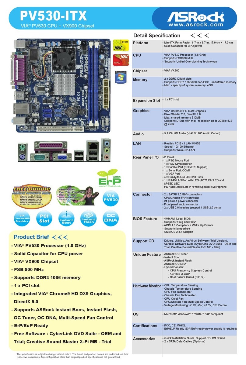
ASROCK H81M-HG4 User manual

ASROCK

ASROCK H81M-HG4 User manual

ASROCK Z97 Pro3 User manual

ASROCK

ASROCK Z97 Pro3 User manual

ASROCK B450M-HDV R4.0 User manual

ASROCK

ASROCK B450M-HDV R4.0 User manual

ASROCK Z68M/USB3 User manual

ASROCK

ASROCK Z68M/USB3 User manual

ASROCK A770DE User manual

ASROCK

ASROCK A770DE User manual

ASROCK 775i65G R2.0 User manual

ASROCK

ASROCK 775i65G R2.0 User manual

ASROCK 960GC-GS FX User manual

ASROCK

ASROCK 960GC-GS FX User manual

ASROCK B85 Pro4 User manual

ASROCK

ASROCK B85 Pro4 User manual

ASROCK Z690 PRO RS User manual

ASROCK

ASROCK Z690 PRO RS User manual

ASROCK G41MH/USB3 R2.0 User manual

ASROCK

ASROCK G41MH/USB3 R2.0 User manual

ASROCK Z97E-ITX/ac User manual

ASROCK

ASROCK Z97E-ITX/ac User manual

ASROCK A75 Pro4 MVP User manual

ASROCK

ASROCK A75 Pro4 MVP User manual

ASROCK B85M BTC User manual

ASROCK

ASROCK B85M BTC User manual

ASROCK M3A785GXH 128M - V1.0 User manual

ASROCK

ASROCK M3A785GXH 128M - V1.0 User manual

ASROCK Z77 OC Formula User manual

ASROCK

ASROCK Z77 OC Formula User manual

ASROCK H81M-ITX User manual

ASROCK

ASROCK H81M-ITX User manual

ASROCK FM2A88M Extreme4+ R2.0 User manual

ASROCK

ASROCK FM2A88M Extreme4+ R2.0 User manual

ASROCK gaia 404 User manual

ASROCK

ASROCK gaia 404 User manual

ASROCK Z170M OC Formula User manual

ASROCK

ASROCK Z170M OC Formula User manual

ASROCK G43TWINS-FULLHD User manual

ASROCK

ASROCK G43TWINS-FULLHD User manual

ASROCK IMB-148 User manual

ASROCK

ASROCK IMB-148 User manual

ASROCK K7VM2 User manual

ASROCK

ASROCK K7VM2 User manual

ASROCK Z790 PG LIGHTNING/D4 User manual

ASROCK

ASROCK Z790 PG LIGHTNING/D4 User manual

ASROCK M3A770DE User manual

ASROCK

ASROCK M3A770DE User manual

Popular Motherboard manuals by other brands

Gigabyte MNJ190I-FH user manual

Gigabyte

Gigabyte MNJ190I-FH user manual

Biostar HI-FI-Z87X-3D Setup manual

Biostar

Biostar HI-FI-Z87X-3D Setup manual

Atmel SAM9753PIA-DK user guide

Atmel

Atmel SAM9753PIA-DK user guide

Coapt GEN2 Handbook

Coapt

Coapt GEN2 Handbook

Supero SUPER P4DL6 user manual

Supero

Supero SUPER P4DL6 user manual

Cypress CY3210-PSoCEVAL1 quick start guide

Cypress

Cypress CY3210-PSoCEVAL1 quick start guide

Fujitsu D2831 Short description

Fujitsu

Fujitsu D2831 Short description

Industrial Computers ADE-6050 user manual

Industrial Computers

Industrial Computers ADE-6050 user manual

Asus TUF Z270 MARK 2 manual

Asus

Asus TUF Z270 MARK 2 manual

DFI NB71-BC user manual

DFI

DFI NB71-BC user manual

Norco POS-7893 user manual

Norco

Norco POS-7893 user manual

Intel DG965MS specification

Intel

Intel DG965MS specification

Asus B85M-VIEW PAKER user manual

Asus

Asus B85M-VIEW PAKER user manual

Asus P5G41T-M LX V2 user manual

Asus

Asus P5G41T-M LX V2 user manual

Gigabyte GA-K8VT800-RH user manual

Gigabyte

Gigabyte GA-K8VT800-RH user manual

Gigabyte Z790M AORUS ELITE user manual

Gigabyte

Gigabyte Z790M AORUS ELITE user manual

Semtech SC120 user guide

Semtech

Semtech SC120 user guide

Meridian Innovation MI0801 user manual

Meridian Innovation

Meridian Innovation MI0801 user manual

manuals.online logo
manuals.online logoBrands
  • About & Mission
  • Contact us
  • Privacy Policy
  • Terms and Conditions

Copyright 2025 Manuals.Online. All Rights Reserved.

16 :
System Panel Header
SATA2 Connectors
17 : SATA_5
18 : SATA_6
SATA3 Connectors
19 : SATA_2
20 : SATA_1
21 : Printer Port Header
USB2.0 Headers
22 : USB10_11
23 : USB8_9
11 : Digital Input / Output
Pin Header
12 : Digital Input / Output Power
Selection
1-2 : +12V
2-3 : +5V
13 :
Digital Input / Output
Default Value
Setting
1-2 : +5V
2-3 : GND
14 : AT/ATX Mode Selection
1-2 : AT mode
2-3 : ATX mode
15 : TPM Header
1 :
8-pin ATX Power Input Connector
2 :
3-Pin CPU FAN Connector (+12V)
3 :
4-Pin CPU FAN Connector (+12V)
4 : DDR3 DIMM Slots
(DDR3_A1, DDR3_B1)
5 : 24-pin ATX Power Input Connector
6 : PWR LOSS Header
Short : Power Loss
Open : no Power Loss
RS-232 Port 4 Pin Headers
7 : COM5
8 : COM6
9 : COM4
10 : COM3
IMB-385
Jumpers and headers setting guide
PIN Signal Name PIN Signal Name
1 SIO_24 2 SIO_20
3 SIO_25 4SIO_21
5 SIO_26 6 SIO_22
7 SIO_27 8 SIO_23
9 JGPIO_PWR1 10 GND
CCTS#1
COM PWR
DDSR#1
DDTR#1
RRXD1
GND
TTXD1
DDCD#1
1
RRTS#1
ATXPWR1
Intel
H81
DDR3_A1 (64 bit, 240-pin module)
DDR3_B1 (64 bit, 240-pin module)
PCI1
PCI2
PCIE1
PCIE2
1
HD_AUDIO1
COM6
1
COM5
1
COM3
1
COM4
1
CMOS
Battery
HDLED RESET
PLED PWRBTN
PANEL1
1
Super
I/O
SATA_ 5
SATA_ 1
SATA_ 2 SATA_ 6
CLRCMOS1
1
CHA_FAN2
64Mb
BIOS
CPU_FAN1
CPU_FAN2
24.4cm (9.6 in)
24.4cm (9.6 in)
USB8_9
1
1
CI2
1
CI1
1
LPT1
USB 3.0
T: USB0
B: USB1
Top:
RJ-45
USB 2.0
T: USB4
B: USB5
USB 2.0
T: USB2
B: USB3
HDMI
BUZZ1
Top:
Line In
Center:
Line Out
Bottom:
Mic In
1
JGPIO1
COM2
VGA1
234
5
6
7
9
10
11
8
12
13
14
16
15
17
18
19
20
21
22
23
24
25
26
27
28
29
30
31
32
33
IMB-385
COM1
PS2
Keyboard
/Mouse
DISPLAY1
ATX12V1
PWR_JP1
1
USB10_11
1
AUDIO
CODEC
CHA_FAN1
TPM1
1
1
1
PWR_LOSS1
JGPIO_PWR1
1
JGPIO_SET1
1
34
35
8 5
4 1
GND
+12V
CPU_FAN_SPEED
FAN_SPEED_CONTROL
GND
+12V
CPU_FAN_SPEED
12
1
24
13
1
GND
GND
S_PWRDWN#
LAD2
SMB_CLK_MAIN
PCICLK
PCIRST#
LAD3
+3V
LAD0
GND
FRAME
SMB_DATA_MAIN
LAD1
SERIRQ#
GND
+3VSB
48MHz +5V
GND
GND
PWRBTN#
PLED-
PLED+
RESET#
HDLED-
HDLED+
1
DUMMY
1
AFD#
ERROR#
PINIT# GND
SLIN#
STB#
SPD0
SPD1
SPD2
SPD3
SPD4
SPD5
SPD6
SPD7
ACK#
BUSY
PESLCT
SATA_5
SATA_6
SATA_1
SATA_2
P/ N: 15G06M006000AK V1.0
*15G06M006000AK*
+5VSB_ATX
The terms HDMI™ and HDMI High-Denition
Multimedia Interface, and the HDMI logo are
trademarks or registered trademarks of HDMI
Licensing LLC in the United States and other
countries.
24 : Chassis Intrusion Header 1
25 : Chassis Intrusion Header 2
26 :
Front Panel Audio Header
27 :
Audio Jacks
Blue - Line In
Green - Line Out
Pink - Mic In
28 : Clear CMOS Header
1-2: Normal
2-3: Clear CMOS
29 :
Top : RJ45 LAN Port
Bottom : USB2.0 (USB4_5)
30 :
4-Pin Chassis FAN Connector (+12V)
31 : Top : USB2.0 (USB2_3)
Bottom : HDMI
ATXPWR1
Intel
H81
DDR3_A1 (64 bit, 240-pin module)
DDR3_B1 (64 bit, 240-pin module)
PCI1
PCI2
PCIE1
PCIE2
1
HD_AUDIO1
COM6
1
COM5
1
COM3
1
COM4
1
CMOS
Battery
HDLED RESET
PLED PWRBTN
PANEL1
1
Super
I/O
SATA_ 5
SATA_ 1
SATA_ 2 SATA_ 6
CLRCMOS1
1
CHA_FAN2
64Mb
BIOS
CPU_FAN1
CPU_FAN2
24.4cm (9.6 in)
24.4cm (9.6 in)
USB8_9
1
1
CI2
1
CI1
1
LPT1
USB 3.0
T: USB0
B: USB1
Top:
RJ-45
USB 2.0
T: USB4
B: USB5
USB 2.0
T: USB2
B: USB3
HDMI
BUZZ1
Top:
Line In
Center:
Line Out
Bottom:
Mic In
1
JGPIO1
COM2
VGA1
234
5
6
7
9
10
11
8
12
13
14
16
15
17
18
19
20
21
22
23
24
25
26
27
28
29
30
31
32
33
IMB-385
COM1
PS2
Keyboard
/Mouse
DISPLAY1
ATX12V1
PWR_JP1
1
USB10_11
1
AUDIO
CODEC
CHA_FAN1
TPM1
1
1
1
PWR_LOSS1
JGPIO_PWR1
1
JGPIO_SET1
1
34
35
32 :
3-Pin Chassis FAN Connector (+12V)
33 : USB3.0 (USB0_1)
34 :
Top : COM2*
Bottom : VGA1
35 :
Top : COM1*
Bottom left: Display1
Bottom right: PS/2 Keyboard/Mouse
(Y Cable)
GND
+12V
FAN_SPEED
* This motherboard supports RS232/422/485 on COM1, 2 ports.
Please refer to below table for the pin denition. In addition, COM1, 2
ports (RS232/422/485) can be adjusted in BIOS setup utility >
Advanced Screen > Super IO Conguration. You may refer to page
30 of our user manual for details.
COM1, 2 Port Pin Denition
PIN RS232 RS422 RS485
1 DCD, Data Carrier Detect TX- RTX-
2 RXD, Receive Data RX+ N/A
3 TXD, Transmit Data TX+ RTX+
4 DTR, Data Terminal Ready RX- N/A
5 GND GND GND
6 DSR, Data Set Ready N/A N/A
7 RTS, Request To Send N/A N/A
8 CTS, Clear To Send N/A N/A
9 No Power/5V/12V N/A N/A