Securitron®R8
Power Relay Module
Quick Start Guide
Overview
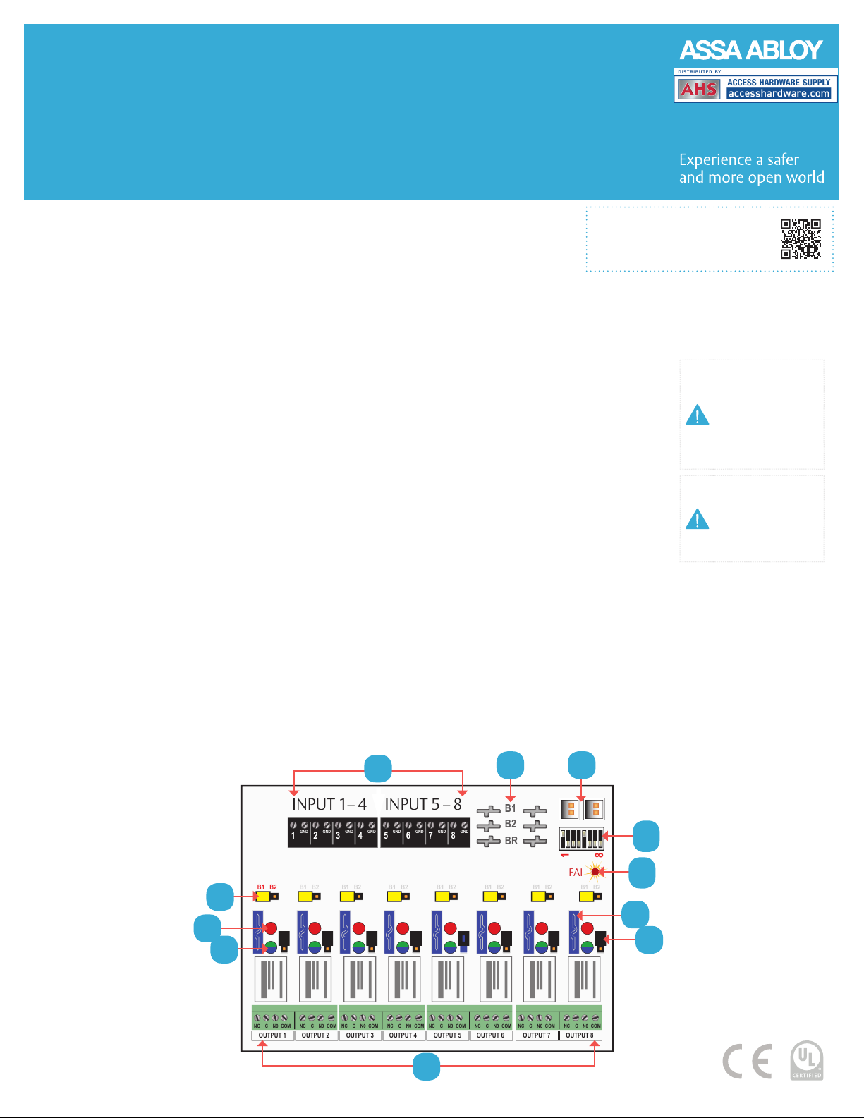
1 FlexIO Connectors – These connectors pass the
FAI signal to the R8 board and pass the FlexIO buss
on to other accessory boards in the system.
2 B1, B2, and BR Connectors – These connectors are the voltage
inputs for the R8 board. BR is the DC Common buss in the system.
B1 is the positive voltage input for the first power supply. In dual
voltage systems, B2 is the input for the second power supply.
3 Zone Inputs (IN1 – IN8) – These are the zone input
terminal strips. These terminal strips are removable and
accept wire sizes from AWG 14 – AWG 22. The terminals
are labeled on the PC board near the terminal strip.
•When using a normally open relay contact input, the
contact is connected across the IN and GND terminals.
•When using an open collector (transistor) input,
the open collector it connected to the IN terminal.
Note that the input source must be common
grounded with the R8 board’s power source.
4 Voltage Selection Jumpers (YELLOW) – These jumpers select the
power input to be used for each output. For single voltage systems,
this jumper should stay in the B1 position. This jumper should be
removed on any zones where a dry contact output is needed.
5 Relay State LEDs (RED) – These LEDs indicate the state
of the output relay. The LED will be lit when the relay is
active and extinguished when the relay is not active.
6 Output Voltage LEDs (Dual Color – BLUE/GREEN) – These
LEDs indicate the voltage of the zone’s output.
•Blue The output is set to 24 V
•Green The output is set to 12 V
•Off Fuse open or dry contact output selected
7 Zone Outputs (01 – 08) – These are the zone output terminal
strips. These terminal strips are removable and accept wire sizes
from AWG 14 – AWG 22. The terminals are labeled on the PC board
near the terminal strip. See the Output Wiring section for more
information. C, NC, and NO are the relay output. Details next page.
8 Dry Output Selection (BLACK)
– When a dry contact output is
needed, this jumper must be removed
in addition to the yellow jumper
for the zone. The output diodes
must also be cut for the zone.
9 Output Fuses (F1 – F8) – These are
the fuses for each zone output.
Fuse numbers correspond with
the zone number (e.g. F1 is the
fuse for OUTPUT1). Fuses are not in
the circuit when the zone is being
used as a relay contact output.
10 FAI LED (RED) – These LED indicates
that the R8 has received an FAI signal from the Securitron
AQL power supply through the FlexIO connector. When
lit, any zones selected to respond to FAI will unlock.
11 FAI Selection Switches (SW1) – These switches select FAI for
each output. Switch 1 is for zone 1, switch 2 for zone 2, etc. When
the switch is ON, the zone will unlock when an FAI is received.
NOTE When a dry
contact output is
needed, the Yellow
and Black jumpers
must be removed
and the output
diodes must be cut
CAUTION When
powering magnetic
loads such as
maglocks, door strikes,
solenoids, etc, each of
these loads must have
a reverse protection
diode either built-in or
external to the device.
Specifications and more details
found in the full manual here.
(Downloadable pdf)
GND GND GND GND
1234 GND GND GND GND
5678
INPUT 1– 4 INPUT 5 – 8
FAI
1
8
GND GND GND GND
1234 GND GND GND GND
5678
NC C N0 COM NC C N0 COM
OUTPUT 1 OUTPUT 2
NC C N0 COM NC C N0 COM
OUTPUT 3 OUTPUT 4
NC C N0 COM NC C N0 COM
OUTPUT 5 OUTPUT 6
NC C N0 COM NC C N0 COM
OUTPUT 7 OUTPUT 8
B2
BR
B1 B2 B1 B2 B1 B2 B1 B2 B1 B2 B1 B2 B1 B2 B1 B2
B1
2
8
10
11
6
5
4
7
9
1
3


