AM SERIES
8
Procedure Items to Note
Inlet piping
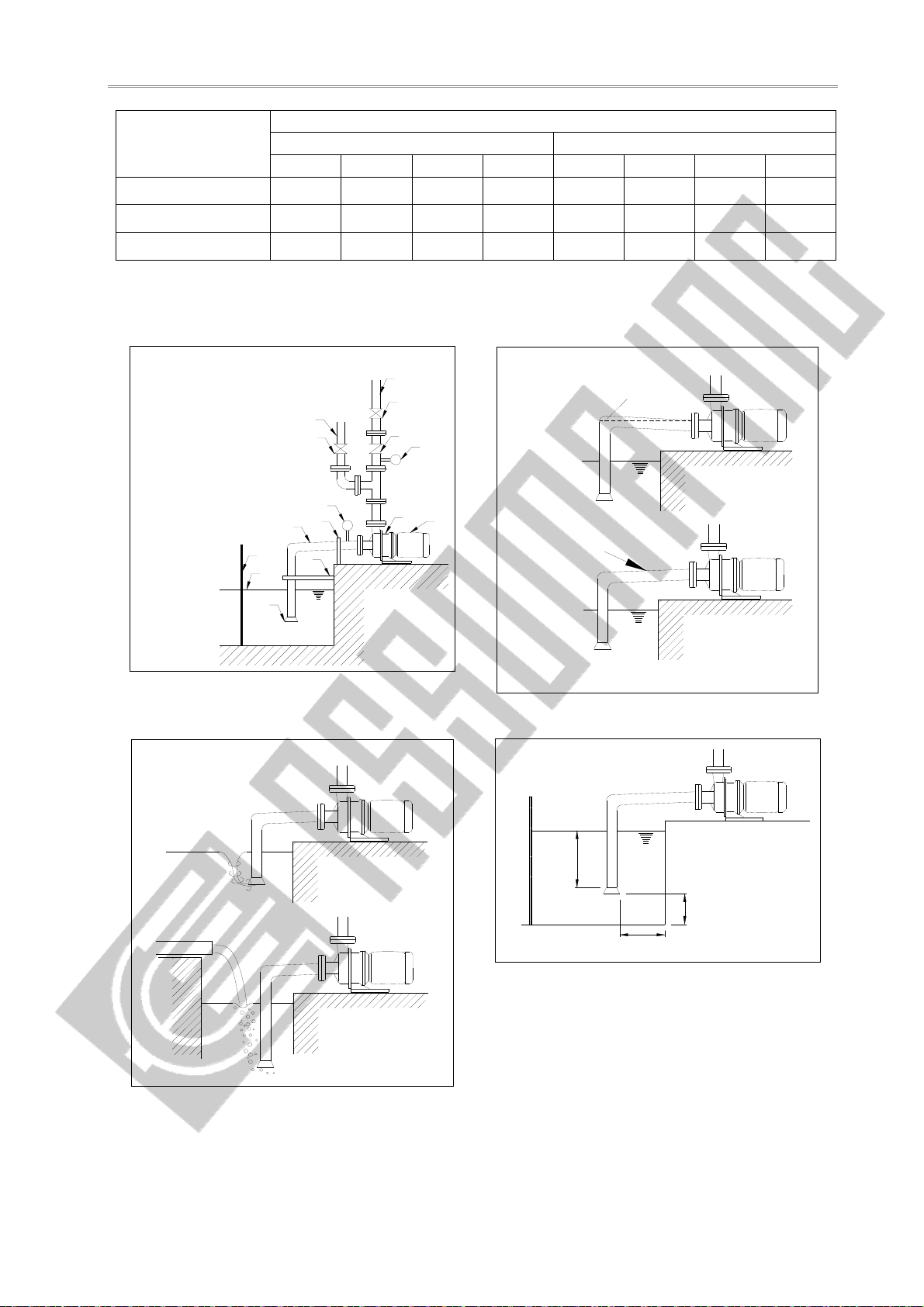
1. There should be at least a 1.5 diameter distance between the pipe inlet
and the closest tank wall to prevent circulation. (see Fig. 4.4)
2. The submerge depth of the inlet should be at least 0.5 m or at least
twice the pipe diameter below the liquid surface. (see Fig. 4.4)
3. There should be a distance of at least 1.5D between the bottom of the
tank and the beginning of the inlet pipe opening. (see Fig. 4.4)
4. If there are two or more inlet piping in the same tank, they should be
placed at least 3D apart to prevent mutually disrupting each other’s
flow.
Foot valve Please install a foot valve if upward suction is used.
Self-priming
cylinder
1. If suction method is upward suction, please install a self-priming
cylinder to prevent dry-running due to a leaking foot-valve.
2. The size of the self-priming cylinder should have a minimum liquid
level of at least 0.5 m above the opening of the pump.
Control valve
1. A control valve should be installed to make disassembling of the pump
easier. The valve should only be shut off when the pump is to be
detached for maintenance or repairs.
2. We recommend the use of valves that have the least loss when fully
opened, like a gate valve.
Filter
1. It is generally not recommended to install a filter in front of a pump,
which can unpredictably increase suction system resistance.
2. If a filter has to be used, it should be cleaned regularly to ensure a
smooth flow.
Vacuum gauge
1.The material used should be corrosion resistant; otherwise, a pressure
gauge diaphragm should be used.
2.During operation, if the vacuum gauge reading fluctuates, either there
are air bubbles in the system or cavitation has occurred.
Outlet Piping
General
requirements
(see Fig. 4.1)
1. The weight of the outlet piping should be properly supported to prevent
putting excessive stress on the pump.
2. A priming piping must be installed if the suction system does not
employ positive pressure, i.e. upward suction.
3. The flow rate in the outlet piping should not exceed 3 m/sec.
4. The ability for each component in the piping system to withstand
pressure should be calculated, to determine the maximum allowable
operating pressure.
Priming piping Upward suction pumps that do not have a self-priming cylinder should
have a priming piping system.
Pressure gauge
1. Pressure gauge used should be able to read beyond the maximum
operating pressure.
2. Pressure gauge should be made of material that is corrosive resistant,
otherwise a diaphragm should be used.
3. A valve can be installed on the piping that leads to the pressure gauge,
to facilitate maintenance and to lengthen the gauge’s service life.
4. During operation, if the pressure gauge reading fluctuates, either there
are air bubbles in the system or cavitation has occurred.