5
Component Installation Notes
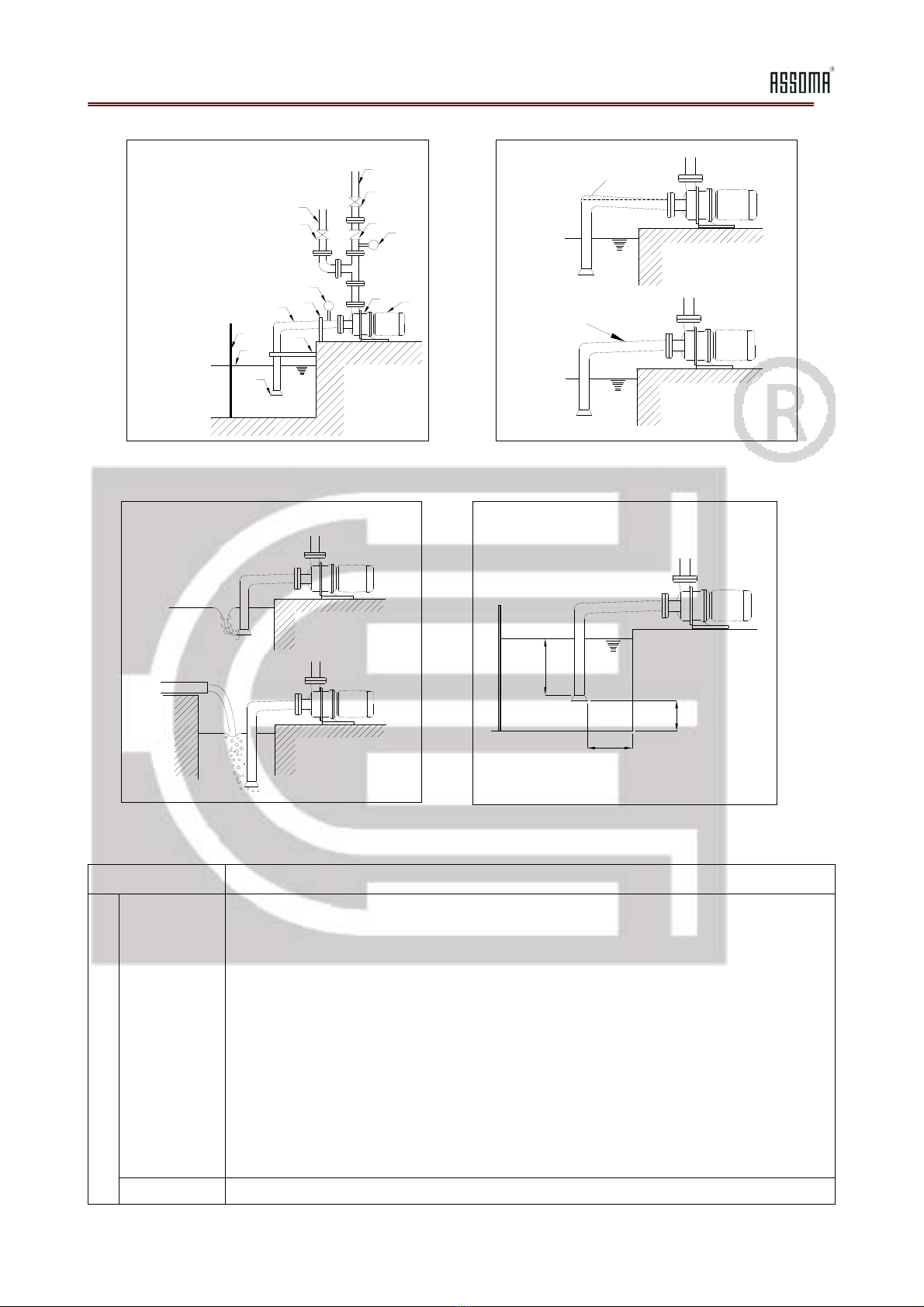
piping the closest tank wall to prevent circulation (see Fig. 4.4).
(2)The submerge depth of the suction pipe inlet should be at least 0.5m or at
least 2D below the liquid surface (see Fig. 4.4).
(3)There should be a distance of at least 1.5D between the bottom of the tank
and the suction pipe inlet (see Fig. 4.4).
(4)If there are two or more inlet piping in the same tank, they should be placed
at least 3D apart to prevent mutually disrupting each other’s flow.
Foot valve Install a foot valve if negative suction or upward suction is used (see Fig. 4.1).
Self-priming
cylinder
(1)For upward suction applications, install a self-priming cylinder to protect the
pump from running dry due to a faulty foot valve.
(2)The self-priming cylinder should provide a minimum liquid level that is at
least 0.5 m above the pump opening.
Control
valve
(1)A control valve should be installed on the suction piping to facilitate
maintenance or repairs. This valve should be open at all times and should
only be closed when there is a need to remove the pump from the system.
(2)A valve with a low piping loss, such as a gate valve, is recommended as the
control valve.
Filter (1)Filters can introduce an unpredictable increase in piping resistance in the
suction system. Therefore, unless absolutely necessary, filters should not be
installed on the suction system.
(2)If filters have to be used, make sure they are cleaned regularly to maintain an
unobstructed flow to the pump.
Vacuum
gauge
(1)The vacuum gauge material should be resistant to the pumped liquid;
otherwise, a pressure gauge diaphragm should be used.
(2)If the vacuum gauge reading fluctuates during operation, either cavitation has
occurred or air bubbles are being sucked into the system.
Discharge System
General
requirements
(1)The discharge piping should be properly secured and supported to prevent
placing excessive stress on the pump.
(2)For systems with a negative suction, priming piping is recommended (see
Fig. 4.1).
(3)The flow velocity of the liquid should not exceed 3 m/s.
(4)For safe operation, discharge piping components must be able to withstand
the pressure generated by the pump.
Priming
piping
Upward suction systems without a self-priming cylinder should have priming
piping installed.
Pressure
gauge
(1)Pressure gauge selected should be able to measure above the maximum
operating pressure of the pump.
(2)The pressure gauge material should be resistant to the pumped liquid;
otherwise, a diaphragm should be used.
(3)A valve can be installed to cut off pressure to the pressure gauge to facilitate
pressure gauge maintenance and to prolong the gauge’s service life.
(4)If the pressure gauge reading fluctuates during operation, either cavitation
has occurred or air bubbles are being sucked into the system.
Check valve A check valve should be installed under the following condition(s):
(1)When the discharge piping is long.
(2)Discharge static head exceeds 10 m.
(3)Discharge pressure exceeds 1.0 kg/cm2and flow velocity exceeds 2.5 m/s.