Asterion XPERT RTL Series User manual

ASTERION RTL
BATTERY SYSTEM MANUAL

ASTERION RTL battery system manual
2
MANUAL EXPLANATION
•COTENT EXPLANATION
Asterion RTL series back-up lithium iron phosphate battery system is developed for backup of
Telecom equipment. Under normal condition, grid AC power supply to rectifier module and the
Telecom loads (the load of figure showed below) and charge battery pack; When the AC power
fail, rectifier module stop power supply, the battery serves for Telecom equipment, to ensure
the Telecom equipment runs normally; This manual contains working principle , structure
,operating parameters and installation of Asterion RTL system
Chapters
Contents
1. Overview
Background, Applications and Advantages
2. Structure and principle
Structure and operating principle
3. Parameters
All parameters of Asterion RTL
4. Installation
Installation and operation
5. Shipping, Storage, and Disposal
Shipping, Storage, Maintenance And Disposal
•BEFORE YOU START
Read all the safety information provided in this document prior to installing and/or operating the
equipment. Contact Asterion Support immediately for a free consultation, if you have any questions
about the handling, operation and safe use of the battery.
To handle or operate with Asterion RTL Power System:
•You must be qualified for electrical work;
•Remove any possible metallic shorting risk of Jewel, Watches, Pens. Metal bars and frames;
•All tools must be insulated.

ASTERION RTL battery system manual
3
•SAFETY SYMBOLS
Symbol
Definition
Important safety information will follow.
DO NOT dispose of battery in a fire.
Recycle or dispose of Lithium batteries in accordance with
local Laws/regulations.
DO NOT dispose of battery in the trash.

ASTERION RTL battery system manual
4
CAUTIONS
What not to do
Please read and comply with the following conditions of installation and use of the battery,
incorrect installation using the battery may cause personal injury or damage to the product.
1.DO NOT throw the battery into water. Store batteries in a cool and dry environment when not
in use.
2.DO NOT put the battery into fire or heat the battery, so as to avoid explosion or other
dangerous events.
3. When charging the battery, please choose specialized charging equipment, and follow the
correct procedures, do not use unqualified chargers.
4. DO NOT reverse positive and negative terminals, do not connect the battery directly to AC
power , avoid battery short circuit.
5. DO NOT use batteries from different manufacturers or different kinds, types together, and do
not use old batteries along with new batteries.
6.DO NOT use the battery when it becomes hot, bulges, deforms or leaks.
7. DO NOT puncture the battery by nail or other sharp objects; Do not throw, stamp on, impact
or hit the battery.
8. DO NOT open or try to repair the battery when it is defective. Warranty invalid if the battery
repaired or disassembled.
Precautions
1. Batteries are half charged before shipment. Don’t use the battery if it’s hot, bulge, or smell
abnormal and so on, and report to Asterion after-sales department immediately.
2. If you need to store the battery for a long time, please charge and discharge the battery
every three months to ensure the best performance, and the best state of charge for
storage is between 50%~60%.
3. Please use the battery in the temperature range which defined in the manual.
4. The state of charge of batteries is 50% before shipment, please charge the battery before
use or test.

ASTERION RTL battery system manual
5
Contents
1OVERVIEW ...............................................................................................................................................................6
1.1 BACKGROUND AND APPLICATIONS.........................................................................................6
1.2 ADVANTAGES............................................................................................................................................6
2PRINCIPLE AND STRUCTURE .......................................................................................................................7
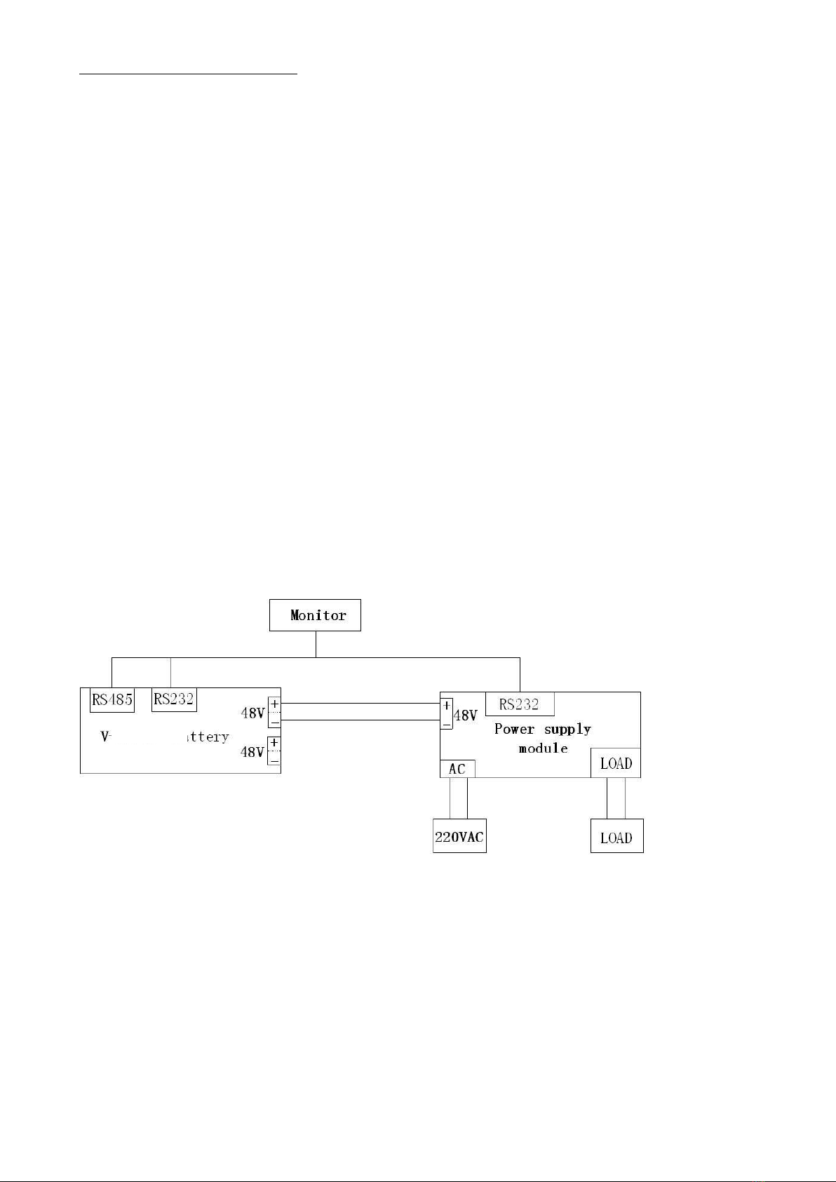
2.1 OPERATING PRINCIPLE......................................................................................................................7
2.2 CONEECTING STRUCTURE..............................................................................................................7
3PARAMETERS..........................................................................................................................................................8
3.1 MODELS........................................................................................................................................................8
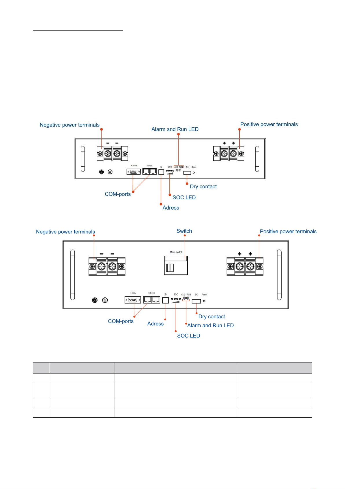
3.2 CONTROL PANEL ...................................................................................................................................9
3.3 BATTERY MANAGEMENT SYSTEM (BMS) ...............................................................................................................................................11
3.3.1 VOLTAGE PROTECTION ...........................................................................................................11
3.3.2 CURRENT PROTECTION...........................................................................................................12
3.3.3 TEMPERATURE PROTECTION ..............................................................................................12
3.3.4CELL BALANCE...............................................................................................................................13
3.3.5 DISPLAY (OPTIONAL).................................................................................................................13
4INSTALLATION AND TESTING ......................................................................................................................15
4.1 PREPARE TO INSTALL..............................................................................................................................15
4.1.1 REQUIREMENTS OF INSTALLATION ENVIRONMENT...........................................15
4.1.2 TOOLS AND MATERIALS ...........................................................................................................16
4.1.3 SITE SURVEY .....................................................................................................................................16
4.1.4 BATTERY CHECK-UP...................................................................................................................17
4.2 INSTALLATION..............................................................................................................................................17
4.2.1 CAUTIONS..........................................................................................................................................17
4.2.2 INSTALLATION STEPS.................................................................................................................18
5SHIPPING, STORAGE AND DISPOSAL .....................................................................................................19
5.1 SHIPPING AND STORAGE .....................................................................................................................19
5.2WARNING AND DISPOSAL ...................................................................................................................19
5.3COMMON FAULTS AND SOLUTIONS............................................................................................20

ASTERION RTL battery system manual
6
1OVERVIEW
1.1 BACKGROUND AND APPLICATIONS
Asterion RTL system combines high-energy lithium-iron-phosphate cells and battery
management system to achieve the highest level of integrity into intelligent control and
monitoringsystem and can be widely applied into different conditions for telecommunication
equipment, mobile comms basic stations etc.
1.2 ADVANTAGES
1. Using the high performance lithium iron phosphate (LiFePO4) as positive materials, the
cycle life is more than 2000 times, floating life up to 10 years, prolongs the service life of
backup power supply system.
2. Using the intelligent management system, realize the monitoring and control of battery
system under charge, discharge, floating and standby, make sure the system is always in
under ideal state of health.
3. Built with comprehensive monitoring system, the battery voltage, current, temperature,
volume, state of health is under monitoring. Communicating with PC to realize the real-
time monitoring and control through the core CPU.
4. The built-in intelligent balance module, to ensure that the consistencyof battery capacity,
to extend the service life.
5. Intelligence-design, meet the national standard requirements, remote-measurement,
remote-communication, remote-control and remote-adjustment.
6. System with intelligent thermal management devices, which insure the system work in a
wide range of temperature, -20 ℃~+60 ℃
1
.
7. With good electromagnetic compatibility and can be matched with standard
communication equipment compatibility.
8. Standard and universal sizes.
1
From -40°С –when using integrated heater option. From -20°С without additional heating.

ASTERION RTL battery system manual
7
2PRINCIPLE AND STRUCTURE
2.1 OPERATING PRINCIPLE
The principle of work of the Asterion RTL series battery system . Under normal condition,
grid AC power supply to rectifier module and the Telecom loads (the load of figure showed
below) and charge battery pack; When the AC power fail, rectifier module stop power supply,
the battery serves for Telecom equipment, to ensure the Telecom equipment runs normally;
when the AC power is switched on again, power rectifier module for Telecom equipment
recover to while charge the battery pack.
2.2 CONNECTING STRUCTURE
Battery system working principle of Asterion RTL series is shown in Figure 2.1.
Figure 2.1 Connecting structure of the battery system

ASTERION RTL battery system manual
8
3PARAMETERS
3.1 MODELS
Asterion RTL series products specifications are in Table 3.1
Таблица 3.1 Asterion RTL series products
Model
48V10Ah
48V20Ah
48V40Ah
48V50Ah
48V100Ah
48V150Ah
48V200Ah
Voltage (V)
48
48
48
48
48
48
48
Capacity (Ah)
10
20
40
50
100
150
200
Energy (Wh)
480
960
1920
2400
4800
7200
9600
Length (mm)
442
442
442
442
442
442
442
Width (mm)
285
285
430
440
480
540
640
Height (mm)
44 (1U)
88 (2U)
88 (2U)
134,5 (3U)
134,5 (3U)
190 (5U)
222 (6U)

ASTERION RTL battery system manual
9
3.2 CONTROL PANEL
Front panel of an Asterion RTL battery with capacity of 10/20/40/50 Ah, BMS, and
components intended for its status indication and monitoring as well as data transmission with
other batteries is shown in Fig 3.2a.
Figure 3.2аAsterion RTL battery with capacity of 10/20/40/50 Ah
Figure 3.2b Asterion RTL battery with capacity of 100/150/200 A*h
Table 3.3 Interface panel specification
№
Name
Function
Note
1
RS-232, RS-485 ports
Communication interfaces RS-485, RS-232
2
Address
Assigned to each module connected in
parallel
See Table 3.4
3
SOC
State of Charge
Four green LEDs
4
ALM
LED indication of alarm signal

ASTERION RTL battery system manual
10
5
RUN
LED indication of an operating device
Always lights bright when
device is operational
6
Dry contact
Special dry contact
7
Reset
Battery system reset
Table 3.4 Assignments of ID address
Code
Address
Assign
Note
ON
ON
ON
ON
0
Model
ON
ON
ON
OFF
1
Model 1
ON
ON
OFF
ON
2
Model 2
ON
ON
OFF
OFF
3
Model 3
ON
OFF
ON
ON
4
Model 4
ON
OFF
ON
OFF
5
Model 5
ON
OFF
OFF
ON
6
Model 6
ON
OFF
OFF
OFF
7
Model 7
Note: In the table 3.4, bits of code correspond with battery module’s ID in binary system.
Table 3.5 LED indicator description
Status
Normal/Alarm/Prot
ect
RUN
ALM
SOC LED
Description
●
●
●
●
●
●
Off/Sleep
OFF
OFF
OFF
OFF
OFF
OFF
All OFF
Standby
Normal
ON
OFF
According to table 3.6
Low capacity alarm
ON
Flash 3
OFF
OFF
OFF
OFF
Charging
Normal
Flash 1
OFF
According to table 3.6
Overcharge
protection
ON
ON
Temperature
protection
OFF
ON
Charging
overcurrent
protection
OFF
ON
Discharging
Normal
Flash 2
OFF
According to table 3.6
Overdischarge
protection
OFF
ON
Temperature
OFF
ON

ASTERION RTL battery system manual
11
protection
Overcurrent / short
circuit during
discharge
OFF
ON
Charging /
Discharging
Alarm signal
Flash 3
Flash 3
According to table 3.6
Table 3.6 Capacity indicator description
Status
Charge
Discharge
Capacity indicator
L1●
L2●
L3●
L4●
L1●
L2●
L3●
L4●
SOC
0 %~5 %
OFF
OFF
OFF
OFF
OFF
OFF
OFF
OFF
5 %~25 %
ON
OFF
OFF
OFF
ON
OFF
OFF
OFF
25~50 %
ON
ON
OFF
OFF
ON
ON
OFF
OFF
50~75 %
ON
ON
ON
OFF
ON
ON
ON
OFF
75~100 %
ON
ON
ON
ON
ON
ON
ON
ON
●Operation indicator
Flash 1
Flash 2
Table 3.7 LED flash definition
Flash type
On
Off
Flash 1
0,5 s
0,5 s
Flash 2
1,0 s
1,0 s
Flash 3
1,5 s
1,5 s
3.3 Battery management system (BMS)
3.3.1 Voltage protection
•Over-charge protection and recovery
During charging, if the voltage of any cell exceeds the setting for cell protection or total
voltage of the system is greater than the setting for the system, the BMS stop charging.
And when all voltage of each cell and total voltage of the battery drop to the recovering-
set values, the protection removes automatically. The voltage settings are shown as No. 1,

ASTERION RTL battery system manual
12
2 in table 3.8.
•Over-discharge protection and recovery
During discharge, if the voltage of any one cell or total voltage of the battery is lower than
the protection settings, the BMS stops discharge. And when all cell voltage and total
voltage go up to recovering-setting, the protection removeautomatically. The settings are
shown as No. 3, 4 in table 3.8.
3.3.2 CURRENT PROTECTION
•Charging over-current protection and recovery
When the charging current bigger than the charging over-current protection current
value andmore than the delay time of charging over-current protection, the system would
enter the mode of charging over-current protection and turn off the charging MOS. The
system would recover from the protection of the charging over-current in every 60
seconds. The settings are shown as No. 6, 7 in table 3.8.
•Charging current limit
During charging, if the charging current is greater than the setting value, the BMS will limit
the charging current to less than the setting value.
•Discharging over-current protection and recovery
When the discharging current beyond the charging over-current protection current and
more than the delay time of discharging over-current protection, the system would enter
the mode of discharging over-current protection and turn off the discharging MOS. The
system would recover from the protection of the discharging over-current in every 60
seconds. The settings are shown as No. 9, 10 in table 3.8.
•Short circuit protection and recovery
When the discharging current beyond the value of short circuit protection and reaches
the delay time of the short circuit protection, the system would enter the mode of short
circuit protection and turn off the discharge MOS. The system wouldn’t recover by itself
unless remove the load or charge the battery. The settings are shown as No. 11 in table 3.8.
•Reverse polarity protection and recovery
When the battery and rectifier are in reserve connection and reaches the delay time of the
reverse polarity protection, the system would enter the mode of reverse polarity
protection and turn off the discharge MOS. The system wouldn’t recover by itself unless
remove the rectifier or properly connected rectifier.

ASTERION RTL battery system manual
13
3.3.3 Temperature protection
•Cell temperature protection
There are several thermal sensors to monitor the cell temperature, if the temperature
of any cell is higher than 70℃or lower than 0℃,the BMS will stop charging, this is
charge temp. protection; If the temperature of any cell is higher than 75℃or lower than
﹣20℃(﹣40℃)
2
,BMS will stop the discharge. This is the discharging protection. The
settings are shown as No. 12 in table 3.8.
•PCB overheat Protection
There is a thermal sensor to monitor the PCB temperature, if the PCB temperature is
higher than 95 ℃, it will trigger the PCBprotection and stop charging or discharge until
the temperature drop to normal range. The settings are shown as 14 in table 3.8.
3.3.4 CELL BALANCE
During charging, If all cell voltages are greater than 3.40V and the voltage difference
between cells ΔU>40mV, BMS will trigger the balancing process, the balance current
is designed base on the capacity of battery pack.
ΔU=max. Cell voltage –min. Cell voltage
3.3.5 DISPLAY (OPTIONAL)
The display screen is only for display –when the battery is on, it can show the battery
information. There are four buttons: Enter, Back, Up, Down.
By pressing the Enter the button, you can check battery cell voltage, Temperature and
Parameters Information. Press the Enter button to check the information of the parameter
that the cursor is pointing at. To scroll through the parameters press Up and Down buttons.
2
When using integrated heater option

ASTERION RTL battery system manual
14

ASTERION RTL battery system manual
15
Table 3.8 Protection settings
№
Type
Function
Setting value
Note
10
20
40
50
100
150
200
1
Voltage
Charge
Cell voltage
protection
3,90 V Protection
Recover at 3.6V
2
Total voltage
protection
56,0 V Warning / 57,0 V Protection
Recover at 54.V
3
Discharge
Cell voltage
protection
2,0 V Protection
Recover at 3,1 V
4
Total voltage
protection
43,2 V Warning/ 42 V Protection
Recover at 46,5 V
6
Current
Charge
Normal
≤5A
≤10A
≤40
≤50A
≤100A
≤150A
≤200A
7
Overcurrent
>5A
>10A
>40
>50A
>100A
>150A
>200A
8
Discharge
Normal
≤10A
≤20A
≤40A
≤50A
≤100A
≤150
≤200
9
Overcurrent 1
15~30
15~30
50~60
60~80
105~129
160~180
210~230
Delay 30 s
10
Overcurrent 2
>30
>30
>60
>80
>129
>180
>230
Delay 3 s
11
Short circuit
≥200 A
≥300 A
Delay 1 ms
12
Temperature
Cell
Range
Charging range –10°С~70°С
Discharging range –20°С~75°С
Delay 1-3 ms
13
Environment
Range
Charging range –10°С~70°С
Discharging range –20°С~75°С
14
PCB
Range
≤95°С
Note: When you choose the model of battery, please choose one which has enough discharging
current to meet your load requirement.

ASTERION RTL battery system manual
16
4INSTALLATION AND TESTING
4.1 PREPARE TO INSTALL
•Safety rules
The installation, operation and maintenance of V-LFP48 series lithium iron phosphate
battery system must be performed by trained and qualified professional personnel. Before
installation and use, please carefully read the product safety precautions and related
operating rules. Strictly abide by the following safety rules and local safety regulations,
otherwise may cause personal injury or damage to the product.
1. Make sure that the Telecom equipment to be connected with the battery system is in
good condition and free from defects;
2. Before installation, make sure that the power supply system is under shut down state,
while the battery system is also under shut down state;
3. All the electricity cables must have corresponding grade of insulation, Please ensure
that no exposed cables;
4. Make sure that the battery and power system are reliable grounding.
4.1.1 Environment requirements
Environment requirements are given in the Table 4.2.
Table 4.2 Requirements towards the environment of installation
Requirement
Value
Operating temperature
Operating range: –20°С (–40°С)3~ +60°С
Storage temperature
–20 °С ~ +60 °С
Relative humidity
<95%
Atmospheric pressure
86 kPa~106 kPa
3
When using integrated heater option

ASTERION RTL battery system manual
17
Site of installation requirements
No current-conducting dust and corrosive gases, no vibrations. Keep
away from heat and flame.
4.1.2 TOOLS AND MATERIALS
Tools and sources of information to be used are given in the Table 4.3.
Table 4.3 Tools and materials
Name
Name
User manual
Oblique mouth clamp
Screw driver
Multimeter
Wrench
Electrostatic prevention bracelet
Pincers
Insulating tape
Wire stripping pliers
Clamp band
4.1.3 Site survey
•Equipment Inspection
1. Check that the equipments connected with batteries are right and in good conditions.
2. Check the DC interface position of the equipment. Check and confirm the output
voltage is in the range showed in table 3.7.
3. Check DC device interface, make sure the maximum output current is matched with
the selected battery.
4. Check the maximal working current of devices backed by the battery , make sure that
the current is less than the maximum discharge current of the products showed in
table 3.8
•Ground check
Check that the battery grounding complies with the local regulations.

ASTERION RTL battery system manual
18
4.1.4 Battery check
1. On the installation site, check the battery packaging to make sure it's intact;
2. Check battery box according to the packing list, make sure all the material is complete, if
any damaged, please fill in the receipt;
3. Please be careful while handling batteries, avoid any damage.
4.2
INSTALLATION
4.2.1 CAUTIONS
When begin to install the battery system, you should pay attention to the following matters:
1. Installation space and load bearing capacity. Make sure that the site’s construction meets
the requirements of the load bearing capacity.
2. Cable specifications. To ensure that the use of the connection of the power supply line can
meet the maximum current requirements of equipment operation.
3. Wiring layout. Ensure that the wiring reasonable, orderly; and consider the moisture-proof,
corrosion prevention.
4. The whole installation process should wear anti-static wristband.
5. The installation site should be at least two people to operate.
Warning: Please ensure the installation site is safe and meets the local regulations before installation.

ASTERION RTL battery system manual
19
4.2.2 INSTALLATION STEPS
Battery installation steps are shown in table 4.4..
Table 4.4 Installation steps
Step №
Name
Definition
1
Turn off power supply
The system should be powered off, to ensure that
there is no electric in installation process
2
Mechanical installation
1. Mounting lugs installation
2. Battery fixed installation
3
Electricalinstallation
1. Grounding cable
2. Power cable installation
3. Connecting equipment installation
4. Communication cable installation
4
Electricalcommissioning
Power system commissioning

ASTERION RTL battery system manual
20
5SHIPPING, STORAGE AND DISPOSAL
5.1
SHIPPING AND STORAGE
•Shipping
According to the provisions of the product can be used in general means of conveyance, but
should avoidthrowing, rain fall, strong radiation and corrosion erosion.during transportation,
please prevent the collision and strong vibration.
•Storage
Store device in the indoor storage, the ambient air temperature is 0 ℃to + 45℃, the average
monthly relative humidity of not more than 90%, the ambient air without corrosive
and flammable and explosive gas; storage warehouse should be ventilated, free of alkaline,
acidic substances and other corrosive gases, without a strong mechanical vibration, shock,
and without strong electromagnetic field and direct sunlight. Capacity was maintained at
50% to 60% stores, and charging the battery every 6 months.
5.2
WARNING AND DISPOSAL
When the ALM lights, battery has been alarmed or protected, please check fault reasons and take
corresponding measures. Table 5.1 below is the main alarm condition.
Table 5.1 The main alarm and protection
State
Type
Indicator
Disposal
Charging
Overvoltage protection
ALM
Stop charge, check module voltage and charger
Overcurrent protection
ALM
Stop charge, check the settings and limitation
Temperature
protection
ALM
Stop charge, wait for the temp recovery
Discharging
Low voltage protection
ALM
Stop discharge, turn to charging mode
Overcurrent protection
ALM
Stop discharge, check if there is an over load
Temperature
protection
ALM
Stop discharge, wait for the temp recovery
This manual suits for next models
7
Table of contents