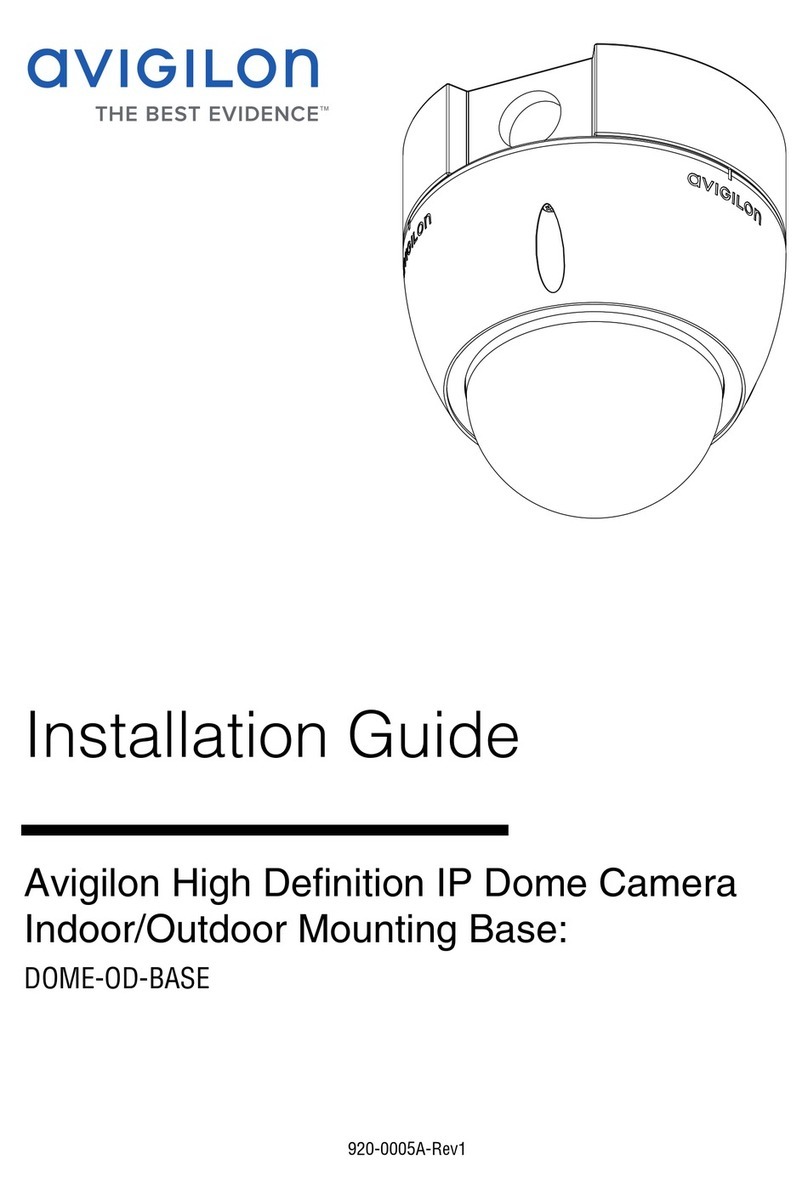
Avigilon ES-HD-HWS User manual

EN English - Instructions manual
ENGLISH
Avigilon High Denition
Camera Housing
ES-HD-HWS, ES-HD-CWS, ES-HD-HWS-LG, ES-HD-CWS-LG

Contents
ENGLISH
1 About this manual...........................................................................................................3
1.1 Typographical conventions.....................................................................................................................3
2 Notes on copyright and information on trademarks .................................................3
3 Safety rules .....................................................................................................................3
4 Identification ...................................................................................................................4
4.1 Product description and type designation.........................................................................................4
4.2 Product markings....................................................................................................................................4
5 Preparing the product for use ......................................................................................5
5.1 Unpacking and contents ....................................................................................................................... 5
5.1.1 Unpacking.................................................................................................................................................................5
5.1.2 Contents...................................................................................................................................................................5
5.2 Safely disposing of packaging material........................................................................................... 5
5.3 Preparatory work before installation ................................................................................................ 5
5.3.1 Attaching the support...........................................................................................................................................5
6 Assembling and installing.............................................................................................6
6.1 Installation ................................................................................................................................................. 6
6.1.1 How to open the housing .....................................................................................................................................6
6.1.2 How to install the camera....................................................................................................................................6
6.1.3 Board description ..................................................................................................................................................7
6.1.4 Connection of the power supply line ...............................................................................................................7
6.1.4.1 Type of cable...............................................................................................................................................................................7
.......................................................................8
6.1.6 Desiccant bag.........................................................................................................................................................8
7 Accessories .....................................................................................................................9
7.1 Heater ......................................................................................................................................................... 9
7.1.1 Heater installation....................................................................................................................................................9
8 Disposal of waste materials..........................................................................................9
9 Technical data............................................................................................................... 10
9.1 General......................................................................................................................................................10
9.2 Mechanical..............................................................................................................................................10
9.3 Electrical ..................................................................................................................................................10
9.4 Environment............................................................................................................................................10
..........................................................................................................................................10
10 Technical drawings
.................................................................................................................................................................................11

Instructions manual - English - EN
3ES-HD-HWS/ES-HD-CWS/ES-HD-HWS-LG/ES-HD-CWS-LG
1 About this manual
Before installing and using this unit, please read
this manual carefully. Be sure to keep it handy for
later reference.
1.1 Typographical conventions
DANGER!
High level hazard.
Risk of electric shock. Disconnect the
power supply before proceeding with any
operation, unless indicated otherwise.
WARNING!
Medium level hazard.
This operation is very important for the
system to function properly. Please read
the procedure described very carefully and
carry it out as instructed.
INFO
Description of system specifications.
We recommend reading this part carefully
in order to understand the subsequent
stages.
2 Notes on copyright and
information on trademarks
The quoted names of products or companies are
trademarks or registered trademarks.
3 Safety rules
The manufacturer declines all
responsibility for any damage caused
by an improper use of the appliances
mentioned in this manual. Furthermore,
the manufacturer reserves the right to
modify its contents without any prior
notice. The documentation contained
in this manual has been collected with
great care, the manufacturer, however,
cannot take any liability for its use. The
same thing can be said for any person
or company involved in the creation and
production of this manual.
• The device must be installed only and
• Before starting any operation, make sure the
power supply is disconnected.
• Do not use power supply cables that seem worn
or old.
• Never, under any circumstances, make any
changes or connections that are not shown in
this handbook. Improper use of the appliance
can cause serious hazards, risking the safety of
personnel and of the installation.
• Use only original spare parts. Non-original spare
other hazards.
• Before proceeding with installation check the
supplied material to make sure it corresponds
4.2 Product markings, page
4).
• This device was designed to be permanently
installed on a building or on a suitable structure.
The device must be installed permanently
before any operation.
• When installing the device, comply with all the
national standards.

EN - English - Instructions manual
4 ES-HD-HWS/ES-HD-CWS/ES-HD-HWS-LG/ES-HD-CWS-LG
• The electrical system to which the unit is
connected must be equipped with a automatic
bipolar circuit breaker. The circuit breaker for
main supply voltage phase units must have a
level of intervention of 20A max. The circuit
breaker for low voltage units must have a level
of intervention of 6A max. This circuit breaker
must be of the Listed type. The minimum
distance between the contacts must be 3mm
with protection against the fault current towards
• Any device which could be installed inside the
product must comply with the current safety
standards.
• If the installation is NEMA TYPE 4X, the installer
must replace the cable glands of the product
with NEMA TYPE 4X cable glands.
•
surges that the equipment will be subjected
to. The category depends upon the location
of the equipment, and on any external surge
protection provided. Equipment in an industrial
environment, directly connected to major
feeders/short branch circuits, is subjected to
Installation Category III. If this is the case, a
reduction to Installation Category II is required.
This can be achieved by use of an insulating
transformer with an earthed screen between
to neutral and from neutral to earth. Listed
SPDs shall be designed for repeated limiting
of transient voltage surges, suitable rated
for operating voltage and designated as
intended for installation on the load side of
the service equipment overcurrent device);
installation and reduction is 5m.
•
• The product is designed to house only cameras
• A disconnecting device, readily and easily
accessible, must be incorporated in the
electrical system of the building for rapid
intervention.
• To connect the power supply line use the
information, refer to the product use and
installation manual.
• Use Listed copper tube crimping lugs for the
connection of the network conductors to the
terminals. The copper tube crimping lugs must
tube crimping lugs examples: RP, BP or YP
4 Identification
4.1 Product description and type
designation
Robust aluminium housing designed to simplify
the installation and service and guarantee total
protection against all environmental conditions.
Its size makes it ideal for housing various
compact zoom lenses.
Very easy to install thanks to the side opening
system that allows the full access to the camera,
lenses and all internal connections.
A wide range of accessories for mounting the
equipment is available thereby satisfying all
installation needs.
4.2 Product markings
See the label attached to the product.

Instructions manual - English - EN
5ES-HD-HWS/ES-HD-CWS/ES-HD-HWS-LG/ES-HD-CWS-LG
5 Preparing the product for
use
Any change that is not expressly approved
by the manufacturer will invalidate the
guarantee.
5.1 Unpacking and contents
5.1.1 Unpacking
When the product is delivered, make sure that the
package is intact and that there are no signs that it
has been dropped or scratched.
If there are obvious signs of damage, contact the
supplier immediately.
Keep the packaging in case you need to send the
product for repairs.
5.1.2 Contents
Check the contents to make sure they correspond
with the list of materials as below:
• Housing
• Housing equipment:
• Allen wrench
• Spacers
• Cable glands gaskets
•
• Bolts and screws
• Screws for camera
• Desiccant bag
• 24V DC cooling fan installed
• 12V DC cooling fan included
5.2 Safely disposing of
packaging material
The packaging material can all be recycled.
The installer technician will be responsible for
separating the material for disposal, and in any
case for compliance with the legislation in force
where the device is to be used.
When returning a faulty product we recommend
using the original packaging for shipping.
5.3 Preparatory work before
installation
5.3.1 Attaching the support
The product must be fastened with
suitable equipment. The fastening means
must guarantee the mechanical seal when
a force equal to at least 4 times the weight
of the device is applied.

EN - English - Instructions manual
6 ES-HD-HWS/ES-HD-CWS/ES-HD-HWS-LG/ES-HD-CWS-LG
6 Assembling and installing
The assembly and installation must be
performed only by skilled personnel.
6.1 Installation
6.1.1 How to open the housing
screws on the side, turn the cover and the upper
half of the body about the opening hinge axis.
Fig. 1ES-HD-HWS and ES-HD-CWS only
Loosen the 4 screws on the base of the enclosure
1
2
Fig. 2ES-HD-HWS-LG and ES-HD-CWS-LG only
6.1.2 How to install the camera
Power supply can be provided by the
board supplied with the product. Make
sure the voltage values are appropriate.
6.1.1
6).
Extract the internal support slide by partially
Move the slide, by sliding it until the holes coincide
use the supplied spacers to correctly position the
01 03
02
Fig. 3
Reposition the internal slide by tightening the
previously loosened screws.
Remove the conductors protective sheathing
6.1.3 Board
7).
The camera’s power supply cable conductors must
be tied up with a cable tie next to the terminal.
Keep the signalling and power supply cables
separated from each other.
Tip: Turning the slide upside down will increase
the vertical space available and is required to
support certain camera and lens combinations.

Instructions manual - English - EN
7ES-HD-HWS/ES-HD-CWS/ES-HD-HWS-LG/ES-HD-CWS-LG
6.1.3 Board description
Connect the safety earth to the relative
terminal of the J1 connector.
The board may appear dierent to that
illustrated.
Depending on the product version, the
board may not be equipped with all
functions.
BOARD DESCRIPTION
Connector Function
IN
)¹
OUT
)²
OUT
)
Tamper switch contacts³
OUT
)
Connector for power supply/jumper
OUT
)
SW1 Tamper switch³
Tab. 11
2
3Optional.
4
on the version. VOUTOUT
relation to the type of power supply installed . VOUT
VIN
J1 J4J2J8
J7SW1 J3 J5
Fig. 4
6.1.4 Connection of the power supply
line
Insert the cables for the connection to the power
supply line inside the housing through the
cable glands. The cable glands are suitable for
conductors with diameters of between 5mm and
10mm. The section of the cable inside the housing
Suitably lock the cable glands.
Remove the conductors protective sheathing
6.1.3 Board
7).
Make sure the earth conductor is at least 10mm
longer than the others.
6.1.4.1 Type of cable
The cable used for the connection to the power
supply line must be suitable for the intended use.
Comply with the current national standards on
electrical installations.

EN - English - Instructions manual
8 ES-HD-HWS/ES-HD-CWS/ES-HD-HWS-LG/ES-HD-CWS-LG
6.1.5 Installation of the version with
double filter for air renewal
During installation pay attention to the
orientation of the air inlet filter fins.
Fig. 5
Depending on the angle of inclination of the
prevent water penetrating in case of rain:
To guarantee the weatherproof, install the housing
on the support following the inclination limits as
shown in the picture.
0˚
45°
45°
Fig. 6Maximum tilt of the transversal axis: 0°.
Maximum tilt of the longitudinal axis: ±45°.
6.1.6 Desiccant bag
Take the dessicant salt bag out of its pack and
insert it into the product.

Instructions manual - English - EN
9ES-HD-HWS/ES-HD-CWS/ES-HD-HWS-LG/ES-HD-CWS-LG
7 Accessories
For further details on configuration and
use, refer to the relative manual.
7.1 Heater
7.1.1 Heater installation
6.1.1
6).
body of the housing.
before attachment to ensure contact and hence
guarantee correct heat transmission.
the camera.
02
01 02
Fig. 7
Plug the multipolar female connector into the
6.1.3 Board
7).
Reposition the internal slide.
Close the housing.
8 Disposal of waste
materials
This symbol mark and recycle system
are applied only to EU countries and not
applied to the countries in the other area
of the world.
Your product is designed and manufactured with
high quality materials and components which can
be recycled and reused.
This symbol means that electrical and electronic
equipment, at their end-of-life, should be disposed
of separately from your household waste.
Please dispose of this equipment at your local
Community waste collection or Recycling centre.
In the European Union there are separate
collection systems for used electrical and
electronic products.

EN - English - Instructions manual
10 ES-HD-HWS/ES-HD-CWS/ES-HD-HWS-LG/ES-HD-CWS-LG
9 Technical data
9.1 General
Constructed from aluminium
Sunshield in ABS
Epoxypolyester powder painting, RAL9002 colour
Stainless steel external screws
9.2 Mechanical
Cable glands: M12, M16, M20
9.3 Electrical
version):
•
•
•
•
blower and thermostat for models with double
•
•
9.4 Environment
Indoor/Outdoor
9.5 Certifications
CE: EN61000-6-3, EN50130-4, EN60950-1,
EN60950-22
bracket with internal cable channel)
channel)

Instructions manual - English - EN
11ES-HD-HWS/ES-HD-CWS/ES-HD-HWS-LG/ES-HD-CWS-LG
10 Technical drawings
d
Fig. 8ES-HD-HWS and ES-HD-CWS.
inches
mm
Usable Area Usable
Area

EN - English - Instructions manual
12 ES-HD-HWS/ES-HD-CWS/ES-HD-HWS-LG/ES-HD-CWS-LG
A-A
B-B
A
A
B
B
[7]
176
[3.9]
99
[4.1]
105
[3.5]
90
[13]
330
[3.5]
88
[0
.7]
17
[6.2]
157 [6.8]
173
[20.2]
514
[2.8]
70
[2.8]
70
[2.8]
70
[2]
52
[8.3]
212 [7.4]
188
[1.6]
40 [4.4]
113 [2.4]
61
[1.5]
39
[5.5]
140
[0.5]
13 [2.4]
62
[1.5]
39
[3.5]
88 [3.5]
88
[8.9]
225
[7.8]
197
[6.7]
171
[15.8]
401
A-A
B-B
A
A
B
B
[7]
176
[3.9]
99
[4.1]
105
[3.5]
90
[13]
330
[3.5]
88
[0.7]
17
[6.2]
157 [6.8]
173
[20.2]
514
[2.8]
70
[2.8]
70
[2.8]
70
[2]
52
[8.3]
212 [7.4]
188
[1.6]
40 [4.4]
113 [2.4]
61
[1.5]
39
[5.5]
140
[0.5]
13 [2.4]
62
[1.5]
39
[3.5]
88 [3.5]
88
[8.9]
225
[7.8]
197
[6.7]
171
[15.8]
401
Fig. 9ES-HD-HWS-LG and ES-HD-CWS-LG.
Usable Area
Usable Area

ES-HD-HWS/ES-HD-CWS/ES-HD-HWS-LG/ES-HD-CWS-LG
© 2014 - 2016, Avigilon Corporation. All rights reserved. AVIGILON and the AVIGILON logo are trademarks of Avigilon Corporation. Other product names mentioned herein may be the
trademarks of their respective owners. The absence of the symbols ™ and ® in proximity to each trademark in this document is not a disclaimer of ownership of the related trademark.
Avigilon Corporation protects its innovations with patents issued in the United States of America and other jurisdictions worldwide: www.avigilon.com/patents. Unless stated explicitly and in
writing, no license is granted with respect to any copyright, industrial design, trademark, patent or other intellectual property rights of Avigilon Corporation or its licensors.

IT Italiano - Manuale di istruzioni
ITALIANO
Alloggiamento per telecamere
Avigilon ad alta denizione
ES-HD-HWS, ES-HD-CWS, ES-HD-HWS-LG, ES-HD-CWS-LG

Contenuto
1 Informazioni su questo manuale...................................................................................3
........................................................................................................................3
2 Note sul copyright e informazioni sui marchi commerciali ......................................3
3 Norme di Sicurezza ........................................................................................................3
4 Identificazione ................................................................................................................4
..........................................................................4
..................................................................................................................4
5 Preparazione del prodotto per l'installazione ............................................................5
.................................................................................................................. 5
5.1.1 Disimballaggio .........................................................................................................................................................5
5.1.2 Contenuto................................................................................................................................................................5
.......................................................................... 5
................................................................................ 5
5.3.1 Fissaggio del supporto.........................................................................................................................................5
6 Montaggio e installazione.............................................................................................6
6.1 Installazione.............................................................................................................................................. 6
............................................................................................................................................6
............................................................................................................................6
....................................................................................................................................7
6.1.4 Collegamento alla linea di alimentazione ....................................................................................................... 7
.................................................................................................................................................................................7
....................................................8
.........................................................................................................................................8
7 Accessori .........................................................................................................................9
............................................................................................................................................... 9
................................................................................................................................9
8 Smaltimento dei detriti..................................................................................................9
9 Dati tecnici ....................................................................................................................10
9.1 Generale ...................................................................................................................................................10
............................................................................................................................................10
..................................................................................................................................................10
9.4 Ambiente.................................................................................................................................................10
9.5 Omologazioni.........................................................................................................................................10
10 Disegni tecnici..............................................................................................................11

Manuale di istruzioni - Italiano - IT
3ES-HD-HWS/ES-HD-CWS/ES-HD-HWS-LG/ES-HD-CWS-LG
1 Informazioni su questo
manuale
leggere attentamente il presente manuale. Tenerlo
a portata di mano per futuro riferimento.
1.1 Convenzioni tipografiche
PERICOLO!
Rischio di livello elevato.
Rischio di scossa elettrica. Se non
diversamente indicato, staccare
l'alimentazione prima di procedere
conqualsiasi operazione.
AVVISO!
Rischio di livello medio.
Questa operazione è molto importante
per il corretto funzionamento del sistema.
Leggere attentamente la procedura
descritta e procedere come indicato.
INFO
Descrizione delle specifiche di sistema.
Si consiglia di leggere attentamente
questa parte al fine di comprendere
letappe successive.
2 Note sul copyright e
informazioni sui marchi
commerciali
3 Norme di Sicurezza
Il produttore declina ogni responsabilità per
eventuali danni causati da un uso improprio
dei dispositivi citati in questo manuale.
Ilproduttore si riserva, inoltre, il diritto di
modificarne i contenuti senza preavviso.
La documentazione contenuta in questo
manuale è stata raccolta con estrema cura,
il produttore, tuttavia, non può assumere
alcuna responsabilità per il suo utilizzo.
Lo stesso vale per qualsiasi persona o
azienda coinvolta nella creazione e nella
produzione di questo manuale.
• Il dispositivo deve essere installato solo ed
•
•
•
•
•
pagina 4).
•
o su una struttura idonea. Il dispositivo deve
essere installato in modo permanente prima di
•
tutte le norme nazionali.

IT - Italiano - Manuale di istruzioni
4 ES-HD-HWS/ES-HD-CWS/ES-HD-HWS-LG/ES-HD-CWS-LG
•
deve avere un livello di intervento di 20A max.
devono avere un livello di intervento di 6A max.
•
•
•
protezioni da sovratensioni esterne fornite.
•
di resistere a temperature di almeno 75 °C.
•
•
un intervento rapido.
•
•
4 Identificazione
4.1 Descrizione del prodotto e
designazione del tipo
ambientali.
tutte le esigenze di installazione.
4.2 I contrassegni del prodotto

Manuale di istruzioni - Italiano - IT
5ES-HD-HWS/ES-HD-CWS/ES-HD-HWS-LG/ES-HD-CWS-LG
5 Preparazione del prodotto
per l'installazione
Qualsiasi modifica che non sia
espressamente autorizzata dal produttore
annulla la garanzia.
5.1 Disimballaggio e contenuto
5.1.1 Disimballaggio
fornitore immediatamente.
5.1.2 Contenuto
• Alloggiamento
•
•
• Distanziali
•
•
• Bulloni e viti
•
•
•
•
5.2 Smaltimento sicuro del
materiale di imballaggio
Tutti i materiali di imballaggio possono essere
responsabile per la separazione del materiale
Al momento della restituzione di un prodotto
originale per la spedizione.
5.3 Preparativi necessari prima
dell'installazione
5.3.1 Fissaggio del supporto
Il prodotto deve essere fissato con le
attrezzature apposite. I mezzi di fissaggio
devono garantire la tenuta meccanica
quando una forza pari ad almeno 4 volte
ilpeso del dispositivo è applicata.

IT - Italiano - Manuale di istruzioni
6 ES-HD-HWS/ES-HD-CWS/ES-HD-HWS-LG/ES-HD-CWS-LG
6 Montaggio e installazione
Il montaggio e l'installazione deve essere
eettuati esclusivamente da personale
qualificato.
6.1 Installazione
6.1.1 Apertura della scatola
Fig. 1ES-HD-HWS e ES-HD-CWS soltanto
1
2
Fig. 2ES-HD-CWS-LG e ES-HD-CWS soltanto
6.1.2 Installazione della telecamera
L'alimentazione può essere fornita tramite
la scheda in dotazione con il prodotto.
Assicurarsi che i valori di tensione siano
appropriati.
6).
Estrarre la slitta di supporto interna allentando
01 03
02
Fig. 3
Riposizionare la slitta interna serrando le viti
7).
Consiglio:

Manuale di istruzioni - Italiano - IT
7ES-HD-HWS/ES-HD-CWS/ES-HD-HWS-LG/ES-HD-CWS-LG
6.1.3 Descrizione della scheda
Collegare la messa a terra di sicurezza al
terminale corrispondente del connettore J1.
La scheda può apparire diversa da quella
illustrata.
A seconda della versione del prodotto,
la scheda potrebbe non essere dotata di
tutte le funzioni.
DESCRIZIONE DELLA SCHEDA
Connettore Funzione
ENTRATA
)¹
)²
)
³
)
)
SW1 Interruttore antimanomissione ³
Tab. 11
2
3
4
ENTRATA
J1 J4J2J8
J7SW1 J3 J5
Fig. 4
6.1.4 Collegamento alla linea di
alimentazione
7).
10 mm più lungo degli altri.
6.1.4.1 Tipo di cavo
Rispettare le attuali norme nazionali sugli impianti
This manual suits for next models
3
Table of contents
Languages:
Other Avigilon Camera Accessories manuals