Astor-Bannerman ABW-CP User manual

Warranty No:
Version 4: 25-09-2019
ABW-CP
Height Adjustable Basin
INSTALLATION and USER GUIDE

Page: 2
Operation
D
O
WN
U
P
Press and hold button
to raise basin
Press and hold button
to lower basin
Operation of the lever tap system
The lever should be FULLY DOWN when off. To operate, rotate the lever clockwise to turn on
the flow of water; rotating the lever further clockwise will make the water hotter, then rotating
the lever anti-clockwise will make the water colder. To turn the water off, rotate the lever
anticlockwise as far as it will go.
Our policy is one of continuous improvement and we therefore reserve the right to make
technical alterations without notice. The content of this publication may not be copied
either whole or in part without the consent of Astor–Bannerman.
Fig 1
Fig 2
Version 4: 25-09-2019

Page: 3
Caution: The unit is fitted with an obstacle sensing switch, if the unit encounters an obstruction
under the front portion of the basin whilst travelling downwards it will automatically stop. Pressing
the ‘Up’ button will allow the obstruction to be removed. Care should be taken to ensure that
whilst the basin assembly is moving downwards there are no obstructions left directly
beneath the basin or rise & fall unit as the obstacle sensing switch is designed to
stop the unit only when the front of the basin is lifted.
If both the ‘Up’ and ‘Down’ buttons are pressed at the same time the unit will not
move.
Cleaning
The basin and vanity top may be cleaned using most mild cleaning agents. Chemical agents must not
be used, i.e. drain cleaners, acetone, oven cleaners or acids. The rise and fall unit and handset
should be cleaned using a warm soapy solution and rinsed with a damp cloth. Attention should
always be paid to instruction labels on the outside of cleaning agent containers. Test the cleaner on
a discrete area (e.g. underneath the unit).
Troubleshooting
In the unlikely event that problems occur with the unit, carry out the following easy checks to
determine whether or not an engineer is required:
Fault: The rise and fall unit does not travel up or down.
Cause: The mains power supply may have been disconnected.
Remedy:
Examine the mains fuses/circuit breakers and reset as necessary and ensure that mains voltage is
fully reconnected. If the unit still fails to operate an electrician needs to ensure that mains
electrical supply is available at the fused spur (a fuse may have blown elsewhere in the circuit).
Fault:
Cause:
The rise and fall unit travels upwards but not downwards.
There may be an obstruction underneath the basin.
Remedy:
Depress the ‘Up’ button on the handset to gain clearance from the obstruction and then remove the
obstruction. The rise & fall unit should then resume normal function.
If the problem persists after carrying out these remedies, please contact Astor-Bannerman (contact
details can be found on the back page of this user guide).
Our policy is one of continuous improvement and we therefore reserve the right to make
technical alterations without notice. The content of this publication may not be copied
either whole or in part without the consent of Astor–Bannerman.
Version 4: 25-09-2019

Page: 4
Technical Specification.
Duty cycle: 10%, Maximum 2 min use/18 min rest
IP Rating: IP X4
Supply voltage: 230V ac
Power:0.25KW
Dry weight: 50Kg
A weighted sound emission<70dB(A)
Our policy is one of continuous improvement and we therefore reserve the right to make
technical alterations without notice. The content of this publication may not be copied
either whole or in part without the consent of Astor–Bannerman.
All dimensions in mm
Fig 3
Version 4: 25-09-2019

Page: 5
Pre-installation information
Plumbing:
Fit cold (on left) and hot (on right) outlets with their centres at 200mm above the floor, pointing
upwards, offset to the left of the centreline of the unit by 140mm terminating with 3/4” BSP
washing machine isolation valves. These feeds will be enclosed by 50x75mm trunking upon
installation. Fit a 32mm/1¼” waste pipe with its centre at 200mm above the floor, on the centreline
of the unit.
Electrics:
The ABW-CP is supplied by mains electric (230v) and transformed to 24v within the unit. A 30mA
RCD protected fused spur is required, with a flush mounted flex outlet cover, on the wall behind the
unit at a height of 1100mm from the floor on the centreline of the unit.
Fixing:
The basin assembly should be fixed to a load bearing wall (i.e. strong enough to carry a 100kg load
on wall fixing) which is flat and free from obstruction from 200mm – 2200mm above the floor. If
the basin needs to be fixed to a stud wall, the wall will need special reinforcement, either
150mm/6" noggins as shown above or 25mm/1" marine or exterior plywood may be used to cover
the entire fixing area, secured to the stud work every 200mm.
Fig 4
Version 4: 25-09-2019

•Measure 1200mm up from the floor along the centreline of the final position of the unit; using a
spirit level, draw a horizontal line either side of the centreline, at least 520mm long
•Place the attachment rail with the open lip upwards, with its holes centred on the horizontal line.
Select two holes in the rail, at least 250mm apart, to use for fixing, and mark the wall through
these holes with a pencil
•Using a 6mm drill bit, drill two full depth pilot holes at the marked positions and then open up in
order to accept the appropriate fixings
•Fix the attachment rail onto the wall with the open lip uppermost, using two suitable fixings.
Ensure that the rail is horizontal using a level (adjust to suit) and check that it is secure
Installation
Please Note: Due to the complexity of different building methods
Astor-Bannerman do not supply installation fixings and anchors.
Important: The attachment rail is designed to only support the weight of the unit and
not the rated load of the sink, this is an installation aid only
Page: 6
Fig 5
Version 4: 25-09-2019

DRAFT
Page: 7
•Fit the trunking (the following steps describe how to mark up and drill the trunking so that it
can be fitted over the top of the supply pipes and isolation valves):
oPosition the trunking in front of the hot and cold water outlets and with its end
resting on the floor
oRemove and retain the trunking cap
oMark on the back of the trunking the top of the isolation valves and the bottom of the
supply pipes
oUse these marks to make a hole large enough for the pipes and isolation valves to
pass through
oRemove the backing paper from the self adhesive tape on the trunking
oPlace the trunking over the pipes and isolation valves but do not allow the tape to
stick to the wall yet
oUsing a level, ensure the trunking is vertical
oPress the self adhesive tape against the wall to secure the trunking
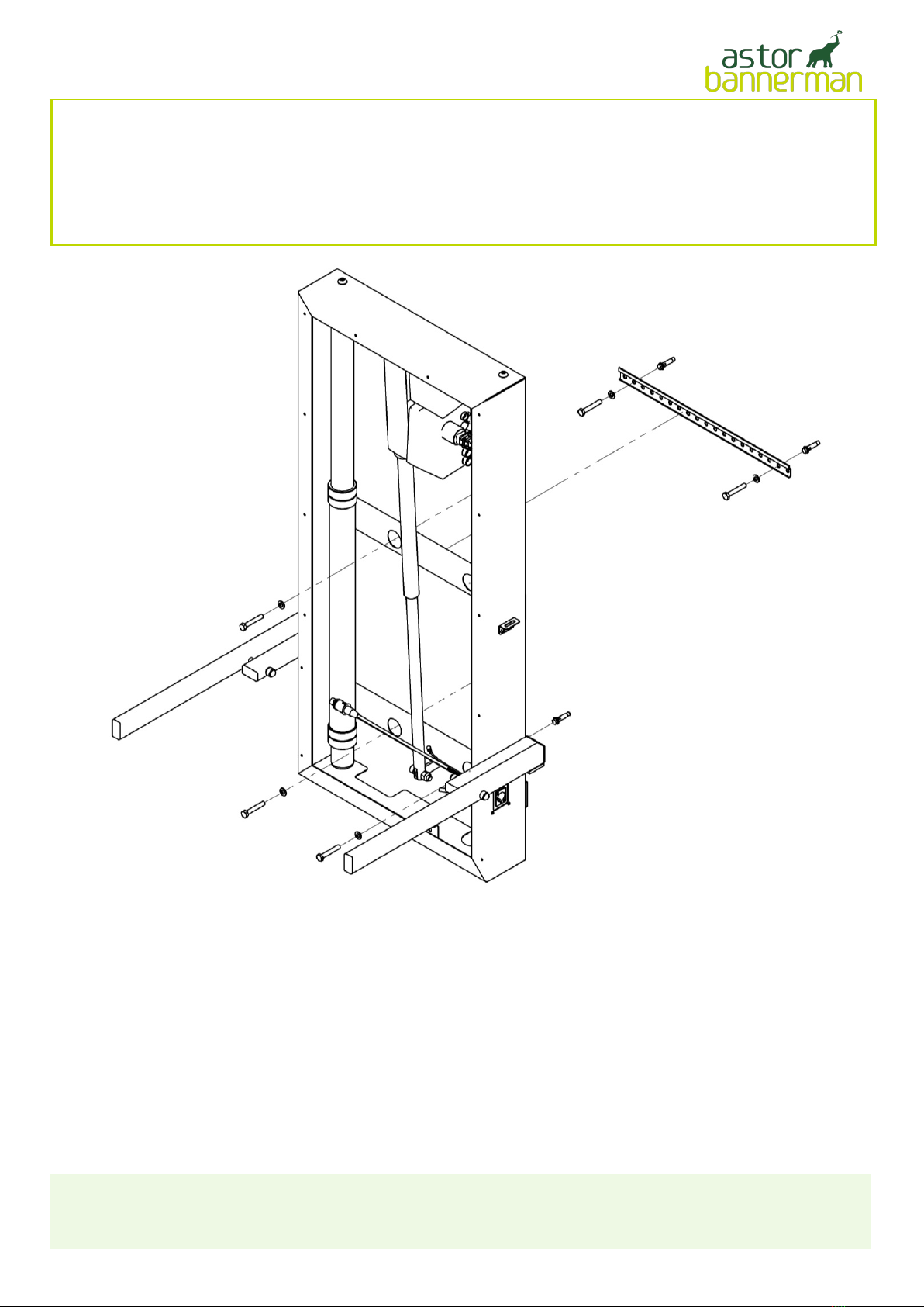
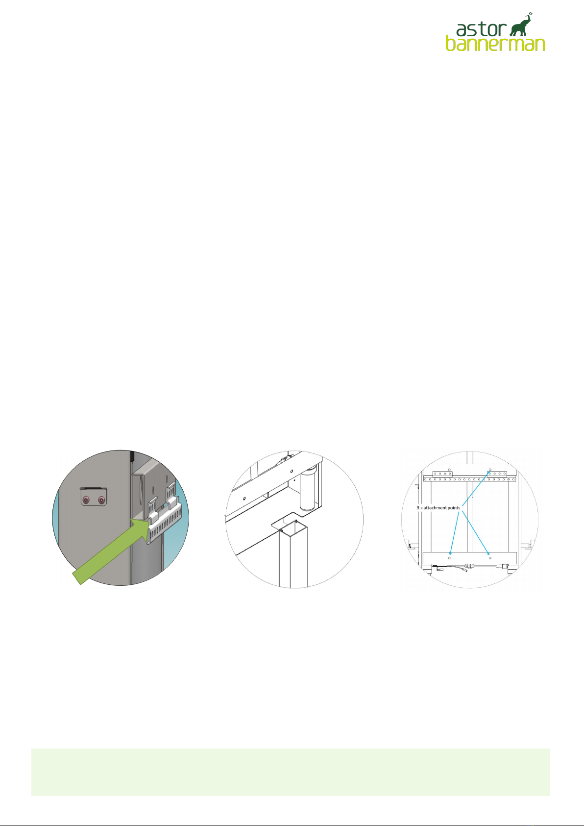
•With assistance, place the rise and fall unit onto the wall ensuring that:
othe two short rails welded to the unit engage with the one on the wall (see Fig 6
below)
othe recess in the underside of the rise and fall unit passes over the trunking
(see Fig 7 below)
•Ensure that the unit is level, then mark the wall through the three attachment points, one on
the upper and two on the lower horizontal beams (see Fig 8, below)
•Remove the unit from the wall and at each of the three marked positions drill a 6mm full-
depth pilot hole
•Open these three holes to accept appropriate fixings
•Fit the fixings into the wall
•With assistance, place the rise and fall unit back onto the wall-mounted rail, ensuring it is
correctly aligned as before
•Fully secure the rise and fall unit to the wall at the three prepared fixing points
•Ensure the previously installed mains supply to the junction box on the wall is switched
OFF
•Electrically connect the rise and fall unit to the fused outlet using the unit's three-core
cable. Ensure there is sufficient slack in the cable to allow the unit to rise and fall
•Fit the handset BEFORE switching the power on
•Secure the handset to the cable tie mount (see diagram on next page for
location of cable tie mount) using the cable tie supplied (see fig 10, p.9)
•Switch on the mains voltage
Check that the Obstacle sensing switch on the arms works properly:
•Operate the lowering function and then lift the right hand arm on the unit to ensure
that the unit stops travelling downwards
•Leave the mains voltage supply switched on
Electrical connection:
Fig 6Fig 7Fig 8
Version 4: 25-09-2019

Page: 8
Assemble the Basin:
•Cover the support arms to protect the basin. Rotate the support arms so they are
horizontal and place the up-turned basin on the arms
•Fit the overflow, hose and waste connection (all from the packing kit) to the basin
•Fit the tap from the packing kit as follows:
oFit the laminar flow straightener to the tap (see page 10 of tap
manufacturer's instructions)
oFit the tap base to the basin (including copper tails) - see Fig 9 above, and
page 10 of tap manufacturer's instructions, steps 1 - 3, but DO NOT
CONNECT THE HOSES YET
Fit the basin assembly to the high-low frame:
•Remove the protective film from double-sided sticky tape fitted to the pivoting arms and
place the basin onto the support arms as far back as possible, ensuring the basin is
under the white plastic upper cover
Plumb in the tap:
•Fit the plumbing to the tap as follows (see diagram, above); fit the two brass elbow/
copper tube/brass tap connector assemblies from the packing kit, by connecting the
elbows to the ends of the copper tails but DO NOT CONNECT THE HOSES YET
Fig 9
Version 4: 25-09-2019

Page: 9
•Ensure both the hot and cold mains water supplies have been flushed and only then
fit the open ends of the supply hoses with the filter screens supplied onto the
isolation valves
•Thread the free end of the supply hoses up through the trunking and through the
recess in the bottom left hand side of the carcass of the rise and fall unit. The hot
and cold outlets, isolation valve and connecting part of the hose above the isolation
valve must be enclosed within the body of the trunking
•Connect the end of the supply hoses with the Conex fitting to the straight tap
connector already fitted
•Fit the tap body to the base - see page 10 of tap manufacturer's instructions, step 4
only - DO NOT TURN ON THE WATER SUPPLIES YET
Fit the mains water supply:
Fit the white plastic lower and upper covers and waste assembly:
•Remove & retain the mushroom heads from the four plastic rivets found in the packing
kit
•Fit the lower cover and align the holes in the cover with the holes in the chassis (see
Fig 12 for locations)
•Fit the rivet bodies through the four holes in the lower cover and into the four holes in
the chassis (see Fig 10)
•Push one of the retained rivet mushroom heads onto each rivet body; this will require a
firm push, it is fully seated once the base of the head is flush with the cover
(cont'd on next page)
Fig 10
Version 4: 25-09-2019

•Operate the handset to raise and lower the basin over the full range of travel to ensure
there is clearance between moving surfaces and surroundings
•Examine for evidence of leaks and correct as necessary
•Examine and clean the assembly
•Complete the warranty documentation and pass the completed warranty document to the
client
Test and set the tap:
•Turn on both water supplies and move the tap handle to both cold and hot positions,
letting the water flow for a few minutes to finish flushing through the system
•With the handle in the hottest position, check the temperature of the water is 41ºC and
correct if necessary, see page 19 of tap manufacturer's instructions
•Fit the cap back onto the trunking
Test the unit:
Page: 10
•
o
o
2
o
•
•
•
, with the elbow horizontal and pointing to your right (Fig 13)
•
2 3
Version 4: 25-09-2019

Astor-Bannerman (Medical) Ltd.
Unit 11F Coln Park Industrial Estate
Andoversford, Cheltenham
Gloucestershire
GL54 4HJ
Tel: 01242 820820
E-mail: [email protected]
Web: www.astorbannerman.co.uk
Directors: Dr. K D Kwok
MBBS MRCP
J Stuart-Smith
MBA BSc
P G Deverson
MIOM
Company registered in England No. 2849299 VAT No. 630 6090 68
Manufacturers Name:
Manufacturers Address:
Equipment Type: ABW-CP Height adjustable basin
I hereby declare that the above product conforms to the following specification:
%%# -EDICAL $IRECTIVE
%. %LECTRICAL 3AFETY
%.1 %-#
%. !SSISTIVE PRODUCTS FOR PERSONS WITH DISABILITY
Signed: Technical Director
Astor-Bannerman (Medical) Ltd
Unit 11F Coln Park
Andoversford
Cheltenham
Gloucestershire
GL54 4HJ
For and on behalf of Astor-Bannerman (Medical) Ltd
Date:
09/9
CERTIFICATE OF CONFORMITY
Page: 11Version 4: 25-09-2019

© 2019Astor-Bannerman (Medical) Limited.
Our policy is one of continuous development, and we therefore reserve the right to make technical
alterations without notice. The content of this publication may not be copied either whole or in part
without the consent of Astor-Bannerman (Medical) Limited.
Original Document Page: 12
Astor-Bannerman Ltd
Unit 11f Coln Park Industrial Estate
Andoversford
Cheltenham
GL54 4HJ
Email: sales @astorbannerman.co.uk
Tel: +44 (0) 1242 820820
Fax: +44 (0) 1242 821110
Version 4: 25-09-2019
Table of contents
Popular Washer manuals by other brands

Schulthess
Schulthess SPIRIT Eco WA 4800 Instruction manual and installation instructions

Alliance Laundry Systems
Alliance Laundry Systems POCKET HARDMOUNT UW50P4 Operation manual

GEORGE TOOLS
GEORGE TOOLS GT9500003 Operating instructions and parts manual

Samsung
Samsung SW80SP user manual

Electrolux
Electrolux ewf 1484 edw user manual

KitchenAid
KitchenAid 8578233 User instructions

Beko
Beko WM 6120 S Installation & operating instructions

Alliance Laundry Systems
Alliance Laundry Systems 800138R2 Installation and operation

LG
LG WT1501C Series owner's manual

Bosch
Bosch WAN2821BSN User manual and installation instructions

Beko
Beko WCY 71232 HPTL user manual

Beko
Beko 60071474CHD1 user manual