ASTRO-PHYSICS 900GTO User manual


1
ASTRO-PHYSICS
900GTO GERMAN EQUATORIAL WITH
GTOCP3 SERVO MOTOR DRIVE
ABOUT THIS MANUAL 3
MODEL 900GTO PARTS LIST 4
MECHANICAL SPECIFICATIONS 5
INTRODUCTION 6
Why Polar Alignment is Important 6
ASSEMBLY DIAGRAM 7
BEFORE YOU LEAVE HOME 8
Gross Latitude Adjustment for 900GTO German Equatorial Mounts 8
Attach Pier Adapter to Pier Post (purchased separately) 10
Standard Pier Adapter (900SPA) 10
Precision-Adjust Rotating Pier Adapter with Azimuth Bearing (900RPA) 11
Hi-Lo Latitude Wedge Pier Adapter Assembly (900WDGA) or Wedge (900WDG) 12
AT YOUR OBSERVING SITE 13
Assemble Pier (purchased separately) 13
Attach Polar Axis Assembly to Pier or Tripod 13
Polar Alignment – Part 1 – Rough Alignment 14
Altitude and Azimuth Adjustments - Rough polar alignment 14
Assemble Declination Axis 15
Removing Declination Axis at the End of Your Observing Session 15
Attach Mounting Plate 16
Fixed Mounting Plate Options 16
Losmandy D-Series Compatible Saddle Plates 17
Astro-Physics Dovetail Options 17
Side-by-Side, Vixen Style and Other Plate Options 18
Attach Counterweight Shaft and Counterweights 19
Attach Mounting Rings and Scope 19
CLUTCH KNOBS, BALANCING AND FINE POLAR ALIGNMENT 20
Understanding the R.A. and Dec. Clutch Knobs 20
Balancing Your Telescope 21
First, Balance the Declination Axis 21
Second, Balance the Polar Axis 21
Polar Alignment – Part 2 – Fine Polar Alignment 21
Methods for ne polar alignment 22
Making Precise Altitude and Azimuth Adjustments 23
Fine Altitude Adjustment 23
Tips for Adjusting the Altitude 23
Fine Azimuth Adjustment 23
Precision-Adjust Rotating Pier Adapter with Azimuth Bearing (900RPA) 24
Standard Pier Adapter (900SPA) and Hi-Lo Latitude Wedge (900WDGA) 24
Azimuth Adjuster Knob Locking Screws: 25

2
CABLE MANAGEMENT 26
900 Motor Cables 26
Accessory Cables 26
Optional Accessories to Prevent Cable Snags 26
Example from International Space Station – Amateur Telescope (ISS-AT) Project 27
MOUNT CARE, CLEANING AND MAINTENANCE 28
Care 28
Cleaning and Touch-up 28
Routine Mount Maintenance 28
TROUBLESHOOTING, TIPS AND SUPPORT 29
Troubleshooting and Tips 29
Additional Support 31
STANDARD PIER ADAPTER OF THE 900GTO MOUNT 32
USEFUL DIMENSIONS FOR OBSERVATORY PLANNING 33
CLUTCH PLUG REPLACEMENT FOR 900 OR 1200 MOUNT 34
Construct Your Own Clutch Plug Extraction Tool 35
CHARACTERIZING THE DEC. AXIS MOTIONS 36
ASTRO-PHYSICS MOUNTING PLATE FASTENER CHART 37

3
ASTRO-PHYSICS
900GTO GERMAN EQUATORIAL WITH
GTOCP3 SERVO MOTOR DRIVE
ABOUT THIS MANUAL
This version of the 900GTO Manual was prepared for the production run of mounts that began shipping in November
of 2011. Most of the information in this manual is applicable to all 900GTO’s that have been produced. Some of the
information in this manual was simply not available when the rst 900GTO’s left our factory back in 1998. This includes
information on newer accessories for the mount that weren’t available for the rst production runs. We have also learned
a few things through experience and the suggestions of our customers that have improved the information that is available
in this manual.
You should also note that this manual is actually one component of a three document system. We have always had two
manuals for each mount - one for the individual mount and another manual for the keypad that applied to all mounts.
Starting in the summer of 2011, we further divided the mount manuals to allow us to present the GTO Servo Motor Drive
System in greater detail. Like the Keypad Manual, the GTO Manual is universal to all mounts that use the Astro-Physics
GTO Servo Motor Drive System with the GTOCP3 Servo Control Box. This 900GTO Manual, on the other hand, will cover
the 900GTO’s mechanical features and physical operations.
Please note that we are continually working to improve our products and, as a consequence, some of the drawings,
photographs and descriptions found in this manual may not reect the latest appearance of the product. That being said,
we suggest that all 900GTO owners adopt this manual for regular guidance with their mounts. The benets of the
improved information should easily outweigh the minor differences between mounts from earlier production runs and the
current one. There will be a few things like the included serial cable, the GTOCP3 Servo Control Box and the Heavy Duty
Azimuth Adjuster that owners of older mounts will not have. In a similar fashion, owners of brand new mounts should be
aware that some of the photos that were used in this manual are of
mounts from earlier production runs. You may therefore see some slight
differences whether you have a brand new mount, or an earlier mount,
but none of these were deemed to be of signicance.
As always, we highly recommend the Technical Support Section of our
Web site for the latest information and for future updated versions of this
manual.
A nal note and an apology to our friends in the southern hemisphere.
Many of the instructions in this manual are written entirely from the point
of view of those of us in the northern hemisphere. Since descriptive
terms like left and right are meaningless without a dened point of
reference, we tend to use east and west to avoid ambiguity. The east
and west sides of a German equatorial mount are, of course, reversed
in the southern hemisphere. At one point, our thought was to always
use phrases like the following: “... on the east side (west side in the
southern hemisphere) ...” This quickly became cumbersome and made
the text more difcult to read. For simplicity, we decided to leave many of the explanations in their northern hemisphere
framework. To our southern hemisphere friends: We love you no less and apologize for this unintended slight. We know,
however, that you are all smart enough to make the necessary translation to “down under” appropriate instructions.
Thank you for your understanding.
Please RecoRd the Following inFoRmation FoR FutuRe ReFeRence
Mount Serial Number: ______________________________
Keypad Serial Number: ______________________________
GTOCP3 Serial Number: ______________________________
Purchase Date: ______________________________

4
MODEL 900GTO PARTS LIST
1 Polar axis assembly (right ascension-R.A.) with GTO Servo Control Box (Model GTOCP3)
1 Declination (Dec.) axis assembly
1 14” (12.875” usable) Stainless counterweight shaft (1.875” dia.) with machined, black-anodized, safety stop
1 Y-cable – R.A. portion is 15.25” long and Dec portion is 40.25” long
1 D.C. power cord (cigarette lighter adapter on one end) - 8’ long
1 Serial Cable – Straight-through –15 feet long
1 GTO Keypad controller with 15’ coiled cable, installed Keypad Protector (KEYPRO), and Instruction Manual
1 Hex key set
2 8-32 Thumbscrews (substitute for set screws to allow quick disconnect of GTO control box)
1 PEMPro™ v.2.x – Full Version - Periodic Error Management software for Astro-Physics mounts (CD-ROM)
1 PulseGuide™ by Sirius Imaging – remote control utility for improved guiding (CD-ROM)
In order to assemble your mount fully, you will need the following items sold separately:
●Telescope mounting plate: Many choices to t your telescope and observing needs. See page 16
●20° to 68° latitude: choose either the Standard Pier Adapter (900SPA) or the Precision-Adjust Rotating Pier
Adapter with Azimuth Bearing (900RPA). Either adapter will come with six 5/16 – 18 X 5/8” button head screws for
attachment to the pier, four pier knobs for attaching the mount to the adapter, and the azimuth block for use with the
Heavy Duty Azimuth Adjuster found on all 900GTO mounts produced after August, 2005 and available as an upgrade
for earlier mounts.
●Tropical or extreme polar latitudes (0° to 20° or 68° to 88° North or South): choose the Hi-Lo Latitude Wedge
Pier Adapter Assembly (900WDGA) or the Wedge alone (900WDG) if you already have the knobs and azimuth block.
●8” O.D. pier: Astro-Physics has several heights and styles to choose from.
●Counterweights: 5 lb. (5SCWT), 10 lb. (10SCWT) and 18 lb. (18SCWT) are available.
●Portable rechargeable 12 volt battery pack: Several sizes and types are available from a variety of vendors.
Be sure that your battery pack can supply adequate power for an entire observing session! Please refer to power
requirements in the GTO Servo Motor Drive System manual. We recommend having separate batteries – one for the
mount and one for all other accessories: camera, dew removers etc.
●Regulated Power Supply (110V AC to 12V DC converter): We offer two choices: 13.8 volt 5 amp supply
(PS138V5A) or 15 volt, 10 amp supply (PS15V10A). Both supplies are ltered and regulated.
Many of these items will be discussed throughout these instructions. Several additional options are available:
●Polar Alignment Scope (PASILL4L): (Prior versions sold by Astro-Physics will also work.) Threads into the base of
the polar axis assembly. Many users nd a polar alignment scope useful for zeroing in on the pole quickly, particularly
with telescopes that are not orthogonal to the mount.
●Pier Accessory Trays and Support Bars: Accessory Tray (TRAY08) and/or Eyepiece Accessory Trays (TRAY08H),
both for 8” piers, with Bi-Level (TRAYSB) or Single Level (TRAYSB1) Support Bars. Handy to keep your eyepieces
and other accessories close at hand!
●Counterweight Shaft Options: Longer counterweight shaft (M12601-D) – 19.5” (18.5” usable) stainless steel shaft
or 9” counterweight shaft extension (M12675)
●900 Flat Surface Adapter (900FSA): for attaching one of our pier adapters to your own custom pier or tripod.
●Losmandy Tripod Adapter (LT2APM): for attaching 900GTO to Losmandy Heavy Duty Tripod or Losmandy MA
Meade Field Tripod Adapter.
● Autoguiding Accessories: Various imaging and CCD based guiding congurations can take advantage of the
900GTO’s autoguider port. The autoguider port receptacle (RJ-11-6) uses the industry standard SBIG ST-4 wiring
setup. See the GTO Manual for more.
●Extension cable for keypad: Please call Astro-Physics to obtain a quote on the length of extension cable you need.
For a complete listing of our 900GTO accessories, visit our website – www.astro-physics.com
Note on Encoders: Mounted encoders can no longer be used with the 900GTO (for mounts shipped starting in October,
2005 – beginning serial number 900451) because of the R.A. shaft re-design. They are not needed since the go-to
functions of the mount are so much more accurate. The encoder that is built into the servo motor itself has a resolution of
0.05 arc seconds vs. 324 arc seconds for mounted encoders.

5
MECHANICAL SPECIFICATIONS
Construction All CNC machined aluminum bar stock, stainless steel, brass; stainless steel fasteners
Worm wheel - R.A. 7.2” (183 mm), 225 tooth aluminum
Worm wheel - Dec. 6.0” (152 mm), 225 tooth aluminum
Worm gear - R.A. Brass, 0.710” (18 mm) diameter
Worm gear - Dec. Brass, 0.705” (17.9 mm) diameter
Thrust Bearing - R.A. 7.0” (178 mm) diameter
Thrust Bearing - Dec. 6.0” (152 mm) diameter
Axis shaft - R.A. 2.20” (56 mm) diameter
Axis shaft - Dec. 1.75” (44 mm) diameter
Shaft axis bearings - R.A./
Dec.
Each shaft is supported by 5 bearing elements; two preloaded ball bearings and 3 sets of
massive thrust bearings
Latitude range 20 - 68 degrees with or without polar scope attached; (0-20 and 68-88 degrees when using
Hi-Lo Latitude Wedge (900WDG or 900WDGA)
Azimuth adjustment Approximately 15 degrees (+/- 7.5 degrees from center)
Setting circle - R.A. 4-minute increments, pointer, engraved both Northern/Southern, Porter Slip Ring
Setting circle - Dec. 1 degree increments, pointer, Porter Slip Ring
Counterweight shaft 1.875” (48 mm) diameter x 14” (356 mm) long [12.875” (327 mm) usable length], includes
large machined safety stop knob. Optional 9” (229 mm) shaft extension is available.
Weight of mount
Total: 54 lb. (24.5 kg)
R.A. axis / polar fork: 26.5 lb. (12.0 kg)
Dec. axis: 17 lb. (7.7 kg)
Counterweight shaft: 10.5 lb. (4.8 kg)
Capacity of mount
Approximately 70 lb. (31.8 kg) scope and accessories (not including counterweights),
depending on length. Recommended for: Astro-Physics and similar fast refractors up to 180
mm f9, 12” Cassegrains, 12.5” CDKs, 12-14” Ritchey-Chretiens. These are only guidelines.
Some telescopes are very long for their weight or heavy for their size and will require
a larger mount. Remember also that imaging requirements are more rigid than visual
observation.
Instrument mounting
interface Refer to the mounting plate section of the manual on page 16.
Pier adapter base
7.730” (196.34 mm) diameter. The base is part of the chosen pier adapter - either the
Rotating Pier Adapter (900RPA), the Standard Pier Adapter (900SPA), or the Hi-Lo Latitude
Wedge (900WDGA or 900WDG). The desired pier adapter must be purchased separately.
For a complete listing of the servo control, power, and periodic error specications, please see the
GTO Servo Motor Drive System Manual.

6
INTRODUCTION
The 900GTO German equatorial was designed to meet the needs of the advanced observer who requires a mount with
maximum strength and rigidity and minimum weight. The excess material in both axes has been carved out while retaining
a heavily ribbed structure for internal strength and rigidity. A unique dovetail was machined into the mating surfaces of the
R.A. and Dec. axes. This feature allows quick and easy assembly in the eld without any tools.
The advent of modern CCD cameras and telescopes with high-resolution optics has placed greater demands on the
ability of mounts to do their part to achieve precision tracking and guiding. At the same time, the mount should be easy
to use with adjustments and setup procedures that are straight-forward and accurate. We have done everything possible
to eliminate the frustrations and limitations inherent in a lesser mount and so put the fun back into the hobby of amateur
astronomy.
The 900GTO employs the reliable and sophisticated Astro-Physics GTO Servo Motor Drive System. This system uses
precise Swiss DC servo motors under the control of the remarkable GTOCP3 Servo Control Box. The GTOCP3 is truly the
“brains” of the system taking your wishes as expressed through an external device like the Astro-Physics GTO Keypad, a
computer, or even some wireless devices, and translating those wishes into actions taken by the mount.
A full range of mount operations is available from the included GTO Keypad. This advanced keypad’s features allow you
to slew automatically to objects in a wide range of databases, as well as any R.A. / Dec. coordinates. A large selection of
common names for stars and other objects makes your selection a snap. Keypad operation is simple and intuitive.
Various additional options such as PulseGuide™ software (included with the mount) and our fully supported AP V2
ASCOM driver are also available to make the connection between you - the astronomer, and the servo system versatile
and straightforward.
The 900GTO’s control and performance options will be further enhanced by the upcoming Astro-Physics Command Center
(APCC). This exciting software is in its last phase of beta testing at the time of this writing, and the rst ofcial release will
be available soon. APCC will fully address all the capabilities of the 900GTO, and will add enhancements not currently
available anywhere else. More information on all the mount control options can be found in the separate Astro-Physics
GTO Servo Motor Drive System Manual.
The 900GTO also includes a full version of PEMPro v.2.x, and as an added bonus, all 900GTO mounts will come pre-
loaded with the custom-tted PEMPro™ corrections from our extensive individual testing that is performed on each and
every mount. While the native, uncorrected, periodic error of your 900GTO will be 7 arcseconds or less, it will have been
reduced even further to maximize performance without auto-guiding.
The 900GTO is equally at home in a permanent observatory or as a portable mounting for remote star parties thanks to
the ease with which the two axes come apart. This is the perfect mount for a mid-sized refractor, Newtonian, Cassegrain
or astrograph. Whether you enjoy visual astronomy exclusively or
plan an aggressive astrophotography or CCD imaging program,
this mount will allow you to maximize your night out under the
stars.
In order to fully enjoy your rst night out, we recommend that
you familiarize yourself with the assembly and basic operation
of the mount indoors. The temperature will be comfortable,
the mosquitoes at bay, and you’ll have enough light to see the
illustrations and read the manuals.
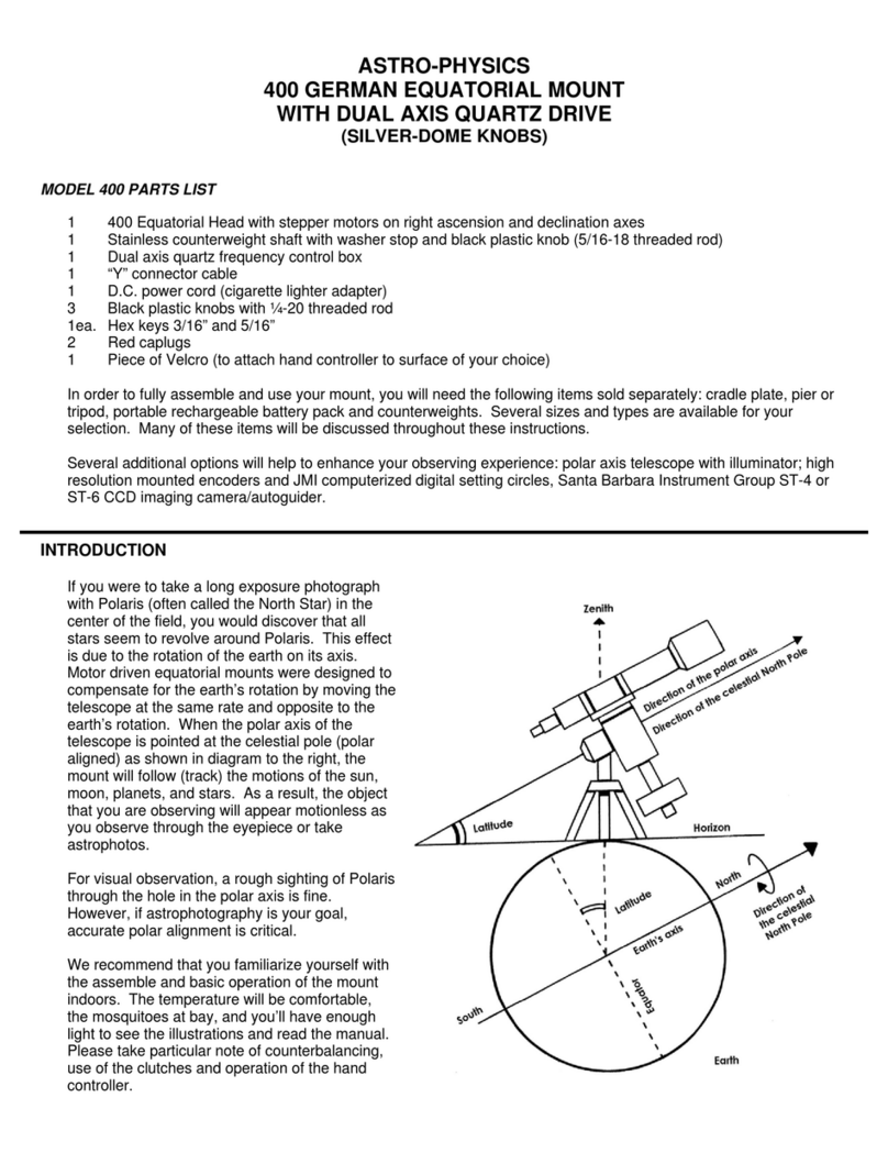
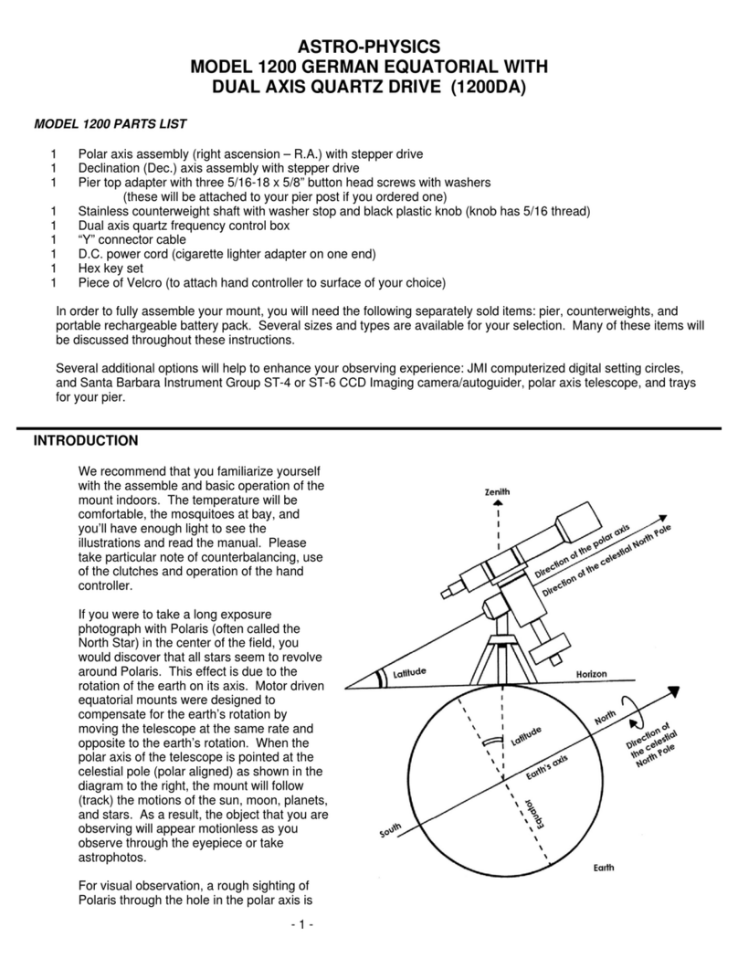
Why Polar Alignment is Important
Polar alignment compensates for the Earth’s rotation.
If you were to take a long exposure photograph with Polaris (often
called the North Star) in the center of the eld, you would discover
that all stars seem to revolve around Polaris. This effect is due to
the rotation of the earth on its axis. Motor driven equatorial mounts
were designed to compensate for the earth’s rotation by moving
the telescope at the same rate and opposite to the earth’s rotation.
When the polar axis of the telescope is pointed at the celestial
pole (polar aligned) as shown in the diagram, the mount will follow
(track) the motions of the sun, moon, planets and stars. As a result,
the object that you are observing will appear motionless as you
observe through the eyepiece or take astrophotos.
7
ASSEMBLY DIAGRAM
Please read all instructions before attempting to set up your 900GTO mount. The model 900 is very rugged, however like
any precision instrument, it can be damaged by improper use and handling. Please refer to the following illustrations. The
parts are labeled so that we can establish common terminology.
The following terms and abbreviations are used interchangeably in these instructions:
● polar axis = right ascension axis = R.A. axis = R.A. housing
● declination axis = Dec. axis = Dec. housing

8
BEFORE YOU LEAVE HOME
Since most of us must set up our instruments in the dark, in the cold or while battling mosquitoes, a bit of preplanning
and organization is important. There are a few simple things that can be accomplished in the comfort of your home before
heading outside.
Gross Latitude Adjustment for 900GTO German Equatorial Mounts
Degree ranges specied below apply to mounts shipped starting in May 2006. Older mounts will have
slightly different latitude ranges unless they were upgraded with the taller polar fork.
The latitude range of the 900 mount is approximately 20-68 degrees. Since most astronomers typically observe within one
latitude range, this rst adjustment is made just once, if at all. Prior to shipment, we preset the mount to your latitude range
for your convenience. If you travel to another observing location, determine the latitude of your observing site and make the
appropriate adjustment. If you live in or plan to travel to tropical locations that are 0 to 20 degrees latitude north or south,
or extreme polar sites that are between 68 and 88 degrees north or south, we recommend our Hi-Lo Latitude Wedge Pier
Adapter Assembly (900WDGA). Pier Adapters are discussed fully later in the manual.
The four positions for the altitude adjustments have the following approximate ranges:
52 degrees to 68 degrees latitude - top position
41 degrees to 59 degrees latitude - third position
30 degrees to 45 degrees latitude - second position
20 degrees to 34 degrees latitude - bottom position
How to change the position of the altitude adjuster
1. Use only the R.A. axis. DO NOT attempt
to make these adjustments with the decli-
nation axis in place and certainly not with
an instrument fully mounted.
2. Loosen both altitude-locking knobs about
1 turn.
3. Locate the side of the polar axis that does
not have the black motor/gear housing
box. Loosen (about 1 turn) the polar axis
pivot screw and altitude adjuster bar xing
screws on this side only. With your hand,
push the polar axis upwards so that the
altitude-locking knobs are positioned at
the top of the altitude adjustment slots
(this is the maximum altitude position).
Some resistance will be felt with this
operation as you are pushing against the
weight of the polar housing and the resist-
ance of the remaining polar axis pivot screw (which has not been loosened).
4. Before attempting to move the altitude adjuster bar, you must tighten the altitude-locking knob on the motor/gear
housing side. This will prevent any downward movement of the polar axis
during positioning of the altitude adjuster bar.
5. While supporting the altitude adjuster bar, remove the two altitude adjuster bar
xing screws that support it on each side (4 screws in all), but keep the two
ends of the bar in contact with the side of the mount, don’t remove it com-
pletely (this tip is for your convenience).
6. Determine the latitude range that you need and position the altitude adjuster
bar so that the hole that is marked “A”, as shown in the diagram, is located at
the appropriate hole position numbered 1-4 in the lower diagram. Note that
hole “A” is located at the rounded part in the center of the altitude bar. Hole
“A” is the “latitude hole.”
7. Attach two of the screws (one on either side of the adjuster bar) through the
appropriate altitude adjustment position hole and into hole A of the adjuster
bar, but do not tighten. Rotate the altitude adjuster bar around this pivot

9
point until the corresponding hole lines up. Consult the labeled photo to determine which hole of the altitude adjuster
bar should be used. Be very careful since the holes marked C and B are very close to one another, as are the holes
marked D and E. The incorrect hole may appear to line up, however it will be slightly off. If you try to attach at the incor-
rect hole, you may strip the threads of the altitude bar. The correct hole will orient the adjuster to be roughly perpen-
dicular to the axis once the axis is lowered into place.
8. Once you have located the correct hole, insert the remaining two screws, and lightly tighten so that you still have some
ability to wiggle the bar.
9. Note that the altitude adjustment knob is at-
tached to a threaded rod that travels through
the altitude adjuster bar. Turn the knob so
that the altitude adjuster bar is positioned
approximately in the middle of the threaded
rod. You should see about half of the
threaded rod protruding from both sides of
the altitude adjuster bar. This will allow you
to move the mount fully within the altitude
range.
10. At the end of the threaded rod mentioned in
the last step, you will see a small brass
altitude adjuster thrust pad. This is the part
that will come in contact with the polar axis
as you ease it back into position. Loosen the
altitude-locking knob (motor/gear side) and
lower the polar axis so that it rests comfortably on this pad. The threaded rod should be positioned at a right angle to
the polar axis housing. Firmly tighten the altitude adjuster bar xing screws.
11. Turn the altitude adjustment knob to raise or lower the polar axis to your approximate observing latitude. Tighten the
altitude locking knobs with nger pressure only. You do not need to tighten with the hex key.
12. Firmly tighten both polar axis pivot screws with the hex key.

10
Attach Pier Adapter to Pier Post (purchased separately)
If you purchased the pier from Astro-Physics, the pier adapter of the 900 will attach right to the top of the pier. If you are
constructing your own pier or tripod, you will need to incorporate this part. Three models of the pier adapter are now
available for use with the 900 from Astro-Physics. The Standard Pier Adapter (900SPA) and the Precision Adjust Rotating
Pier Adapter (900RPA) are the choices for people living within the mount’s 20 to 68 degree latitude range. For customers
in tropical or extreme polar latitudes, the third adapter: the Hi-Lo Latitude Wedge is also available as either a complete
assembly (900WDGA) or as the Wedge alone (900WDG). If you have more than one pier, you may wish to purchase two
adapters so that you can leave them attached permanently. You will probably want to attach the pier adapter to the pier
post before going to your observing site. We recommend that you leave whichever pier adapter you choose attached to
your pier post for transport and storage. These pier adapters can be used with all prior versions of the 900 mount.
If you did not purchase one of our pier adapters described below - for instance, if you purchased the Monolith Pier from
Particle Wave Technologies, you will need to purchase the Pier Adapter Knob Kit (part# 9KBKIT) in order to attach your
mount to the Monolith.
Important notes for all three pier adapters or when using the Monolith Pier :
● The washers for the pier adapter knobs must be positioned
with the smooth surface and rounded edge down so that the
assembly can be adjusted back and forth. (Not important for
the Precision-Adjust Rotating Pier Adapter.)
● Do NOT remove the center pivot screw. Just as the name
implies, this is the point around which the mount rotates
(pivots) when making azimuth adjustments. The screw head
has been machined to assure a close t. Please do not
replace it with another screw.
Standard Pier Adapter (900SPA)
This 900 Pier Adapter is similar to those that we have included with mounts in the past, however the azimuth adjuster block
is slightly taller to accommodate the improved azimuth
adjuster assembly on all 900GTO mounts produced after
August, 2005 (and all upgraded older mounts). If you have
a permanent installation, this base is a good choice since
you will not have to set up every session.
The adapter includes the machined at plate, four
machined aluminum lock knobs with 1/4“ ID x 1.0” OD
stainless washers, the azimuth adjuster block, center
pivot screw and six 5/16-18 x 5/8 button head screws and
washers. All machined parts are black anodized. The
Standard Pier Adapter was designed to t into a 8” x 0.094”
wall tube.
Attach to an Astro-Physics pier: To attach the pier adapter
to your Astro-Physics pier, simply set the adapter into the
top of the pier post, make sure the azimuth adjuster block
is on the north side, and fasten from the side with the six
screws and washers provided.
Attach to a at surface on your own pier: If you are
mounting to a at surface of your own design, simply use
four 1/4–20 stainless steel cap screws of appropriate
length, fastened through the top of your adapter. Refer
to the diagram in the back of the manual for bolt pattern
information.
If you prefer a more nished look, you may wish to
consider using our 900 Flat Surface Adapter (900FSA). The Flat Surface Adapter bolts onto the at plate on top of your
pier or tripod, then the Standard Pier Adapter slips in (just as it ts into our pier) and you fasten from the side with the six
screws and washers provided with the Standard Pier Adapter. The bolt circle for attaching the 900 Flat Surface Adapter to
your pier is 7.230” diameter.
Using an ATS pier: The O.D. of the plate will need to be modied by ATS for an additional charge.
900SPA Standard Pier Adapter
Azimuth Adjuster
Block
Pier Adapter Knobs
and Washers
Tapped Holes
for attaching
ADATRI (3)
Center
Pivot
Screw
Direct Bolt
Holes for
Flat Surface (4)

11
Precision-Adjust Rotating Pier Adapter with Azimuth Bearing (900RPA)
This pier adapter was designed for very accurate and smooth adjustment of the azimuth angle without loosening the lock-
down knobs on the base of the mount. The top plate of the adapter rotates through the 900GTO mount’s full 15 degrees of
azimuth motion. (It does not rotate through a full 360 degrees!) This Precision-Adjust Rotating Pier Adapter is the ideal
choice for portable setups as it makes azimuth adjustment so easy. Upgrade your previous model 900 mount (any version)
and enjoy the ease of use. Do a setup, followed by a ne polar alignment at a remote site just once, and you will wonder
how you ever got along without this pier adapter!
The adapter includes the Rotating Pier Adapter assembly, four machined aluminum lock knobs with 1/4“ ID x 1.0” OD
stainless washers, a tall version of the azimuth adjuster block,
center pivot screw and six 5/16-18 x 5/8 button head screws and
washers.
Attach to an Astro-Physics pier: Simply t the Precision-Adjust
Rotating Pier Adapter into your Astro-Physics Portable Pier just
like the Standard Pier Adapter and fasten it from the side with
the six screws and washers provided. Again, make sure that the
Azimuth Adjuster Block is on the north side.
Attach to a at surface on your own pier: The Precision-Adjust
Rotating Pier Adapter must t inside another part and be bolted
from the side. It cannot be bolted through the top as you can
with the Standard Pier Adapter. We recommend our 900 Flat
Surface Adapter (900FSA). The Flat Surface Adapter bolts onto
the at plate on top of your pier or tripod, then the Precision-
Adjust Rotating Pier Adapter slips in (just as it ts into our pier)
and you fasten from the side with the six screws and washers
provided with the Precision-Adjust Rotating Pier Adapter. The
bolt circle for attaching the 900 Flat Surface Adapter to your pier
is 7.230” diameter.
Using an ATS pier: If you plan to use an ATS pier, the O.D. of the plate will need to be modied by ATS for an additional
charge.
The two recessed screws (3/16 hex), shown by the arrows, adjust the tension between the two plates of the Precision-
Adjust Rotating Pier Adapter. These are preset to an optimal tension and should rarely, if ever, need to be re-adjusted.
You do not need to tighten or loosen these two screws as part of your normal polar alignment routine. For more detailed
information regarding this adapter plate, please review the Adobe Acrobat document entitled “Precision-Adjust Rotating
Pier Adapter(900RPA) – Information and Instructions” on the Technical Support page of our Web site.
900RPA Precision-Adjust
Rotating Pier Adapter
Center
Pivot Screw
Pier Adapter
Knobs and Washers
Tension
Adjustment Screws
Azimuth
Adjuster Block

12
Hi-Lo Latitude Wedge Pier Adapter Assembly (900WDGA) or Wedge (900WDG)
for 0 - 20° or 68° - 88° Latitude – North or South
If your latitude is between 20° north and 20° south or between 68° and 88°, either north or south, this wedge assembly
includes everything you need to place your 900 mount in the proper position.
This adapter includes the machined wedge and at plate, the 1.2” Azimuth Adjuster Block, four Pier Adapter Knobs with
1/4” ID x 1” OD at washers, the center pivot screw, six 5/16-18 x 5/8 socket buttonhead screws and six 5/16 x 9/16”OD x
0.060” at washers, which enable you to attach the pier adapter to your Astro-Physics pier.
Please note:
1. If you already own another adapter, the Hi-Lo Latitude Wedge may be purchased alone, without the Pier Adapter
Knobs, Azimuth Block or Center Pivot Screw. (900WDG)
2. The photo shows the Hi-Lo Latitude Wedge
ready to be used at tropical latitudes with
the Azimuth Adjuster Block on the low side.
For extreme polar latitudes, the plate on
top of the wedge can be turned around to
extend the useful range of your 900GTO
above 68° latitude. Simply remove the two
side knobs and then remove the six screws
that attach the at plate to the wedge.
Rotate the at plate 180° and re-assemble
with the Azimuth Adjuster Block on the high
side.
Attach to an Astro-Physics pier: To attach the
Hi-Lo Latitude Wedge to your Astro-Physics
pier, simply set the adapter into the top of the
pier post, make sure the azimuth adjuster
block is on the north side, and fasten from the
side with the six screws and washers provided.
Attach to a at surface on your own pier: The Hi-Lo Latitude Wedge must t inside another part and be bolted from
the side. It cannot be bolted through the top as you can with the Standard Pier Adapter. For custom installations, we
recommend our 900 Flat Surface Adapter (900FSA). The Flat Surface Adapter bolts onto the at plate on top of your pier
or tripod, then the Hi-Lo Latitude Wedge Pier Adapter slips in (just as it ts into our pier) and you fasten from the side with
the six screws and washers provided. The bolt circle for attaching the 900 Flat Surface Adapter to your pier is 7.230”
diameter.
Using an ATS pier: The O.D. of the plate will need to be modied by ATS for an additional charge.

13
AT YOUR OBSERVING SITE
Assemble Pier (purchased separately)
Begin by assembling the portable pier at the desired
observing location. Take note which direction is
north. (These instructions are for the Astro-Physics
Portable Piers. For other piers, please follow the
manufacturer’s instructions.)
1. Slide the three legs onto the nubs of the base
and rotate the assembly so that one of the legs
points toward north (or south, if that is your
preference).
2. Place the pier post on the base orienting the
center azimuth block directly north. If you choose
to have one leg north, then the pier adapter plate
will have to be installed with the azimuth block
directly over a turnbuckle. If you have one leg
south, the pier adapter plate will have to be in-
stalled with the azimuth block over and between
two of the pier post turnbuckles.
3. Attach the tension rods. The turnbuckles should
be drawn tight until the whole assembly is stiff
enough to support your weight without move-
ment.
Attach Polar Axis Assembly to Pier or Tripod
In order to track the motion of astronomical objects, the polar axis must be positioned so that an imaginary line drawn
through the center of the axis points toward the celestial pole. At this stage of the assembly process, you want to position
the pier and mount so that it points roughly north, if you have not already done so.
1. Remove the four (4) Pier Knobs on the Pier Adapter and keep them close at hand.
2. Prior to lifting the polar axis assembly into place, turn the ne azimuth adjustment knobs so that the space between
them is wide enough to allow the center azimuth block to t easily between them. See photo at right. Ensure both Pier
Adapter top and polar axis assembly mating surfaces are clean and free of dirt. If you are using the Rotating Pier
Adapter, make sure that the Altitude Adjuster Block
is centered in the slot of the top plate.
3. Place the Polar Axis Assembly onto the Pier Adapter
so that the Azimuth Adjuster Block ts between the
ne Azimuth Adjustment Knobs. The Center Pivot
Screw on the Pier Adapter (all models) will help you
center the mount on the adapter.
4. Move the base of the polar axis assembly so that the
threaded holes of the Pier Adapter top can be seen
through each of the four slots.
5. For the Standard Pier Adapter or 900 Hi-Lo Latitude
Wedge, thread the four Pier Knobs loosely in place
(you will tighten these later after polar alignment).
For the Rotating Pier Adapter, go ahead and tighten
the four Pier Knobs securely.
6. Do not tighten the two Azimuth Adjustment Knob Locking Set Screws located on top of the assembly. These will be
explained later.
Allow Space for Azimuth Adjuster Block

14
Polar Alignment – Part 1 – Rough Alignment
We recommend that you accomplish your polar alignment in two phases – rough alignment and ne alignment. Fine
alignment will be discussed in a later section of this manual.
Altitude and Azimuth Adjustments - Rough polar alignment
For rough polar alignment, your goal is to sight the celestial pole when looking through the polar alignment sight hole in the
center of the polar axis. You will need to make altitude (up/down) and azimuth (side-to-side) adjustments to the position of
the mount.
If possible, we recommend that you do your rough polar alignment with the R.A. axis only since you will be making major
adjustments to the position of the mount at this time. The remainder of the mount, telescope and counterweights will add
considerable weight and require more hand effort. Later, you will do your nal polar alignment with the telescope and
counterweights attached, but the adjustments will be comparatively small. An inclinometer and a compass adjusted for
magnetic declination at your location can be very
helpful for daytime setup. Many smart phones have
apps for these functions. In addition, be sure to learn
the Daytime Polar Alignment Routine as described in
the keypad manual. It is a great method for rough
alignment, although it does require a fully assembled
mount.
1. If the Polar Scope (PASILL4L) is installed, you
may remove it to complete these steps.
2. If you examine the polar axis assembly, you will
see that the center of the R.A. shaft is hollow. If
you have the Standard Pier Adapter or the Hi-Lo
Latitude Wedge Pier Adapter and have not done
so already, slightly loosen (1/2 turn) the four pier
knobs. If you have the Precision-Adjust Rotating
Pier Adapter you do NOT loosen the Pier Knobs.
NOTE: If you have already attached the Dec. axis,
remove the sight hole cover and rotate the internal Dec. shaft by moving the top of the Dec. axis (or the cradle plate if it
is attached) to reveal the sight-hole that has been drilled into it. Now, you can look through the shaft to the other side.
3. Azimuth adjustments: To begin with, move or turn the entire pier or tripod east or west until the mount is oriented
approximately towards the pole (an imaginary line drawn through the hollow shaft). Use the two ne azimuth adjust-
ment knobs, one on each side of the mount, to make adjustments after the pier is as well placed as possible. You must
back off the opposing azimuth knob in order to move the other knob in that direction. Please refer to the photos below.
These photos also illustrate the 15 degrees of azimuth adjustment possible with this mount.
One full turn of the azimuth knob is approximately 0.53 degrees (31.8 arcminutes). Small gradua-
tions are 1.06 arcminutes; long graduations are 5.3 arcminutes.
The best adjustment technique to use with the Astro-Physics Heavy Duty Azimuth Adjuster, with its clear registration
marks for ne adjustment, is to back off one of the knobs by a set amount (a certain number of registration marks) and
then to turn the other knob until you re-establish contact on both sides of the Azimuth Adjuster Block. You can very
precisely zero in on the desired position with no backlash or ambiguity on the position. You can also always go back to
Pier West of True North - Adjusted East Pier East of True North - Adjusted West
N
N

15
the precise starting point if for some reason you overshot your mark (or if you adjusted the wrong way), because you
know exactly how far you’ve gone. This is explained further in the section on Fine Polar Alignment.
4. Altitude (latitude) adjustments: Loosen the altitude locking knobs. Move the polar axis up or down with the large
altitude adjustment knob located in the front of the polar axis assembly. For rough alignment with a mount that is not
fully loaded, remove the tommy bar. Later on, during ne alignment, when the mount is loaded, and the adjustments
are small, the tommy bar can be positioned in any of the threaded holes located in the altitude adjustment knob to help
you turn the knob.
One full turn of the altitude knob is approximately 0.64 degrees (38 arc minutes) There are 30
dimples on the altitude knob. ~ 1.266’ or 00*01:16 per dimple.
5. Continue your azimuth and altitude adjustments until you can sight Polaris in the polar alignment sight hole. At this
point, you have achieved a rough polar alignment, which may be sufcient for casual visual observations, if you are
not planning to slew to target objects with the keypad. When the R.A. motor is engaged (the power is plugged in), it will
compensate for the rotation of the earth and keep the target object within the eyepiece eld of view. Your target object
will slowly drift since polar alignment at this stage is only approximate. However, you can make corrections with the N-
S-E-W buttons of your keypad controller.
6. Tighten the altitude locking knobs by hand.
7. If you are using the Standard Pier Adapter or the Hi-Lo Latitude Wedge, tighten the pier knobs rmly by hand. On the
Precision-Adjust Rotating Pier Adapter, the knobs will already be tight.
Assemble Declination Axis
1. Do not have your telescope or counterweights connected to the
Dec. axis assembly for either assembly or disassembly of the
Dec. and R.A. axes.
2. Position the R.A. axis as shown in the illustration at right with
the single pocket “A” at the top, opposite the altitude adjuster
knob. Firmly tighten R.A. clutch knobs.
3. During shipment, the Dec. axis assembly lock knobs will be fully
screwed into the Dec. axis. For correct assembly, these lock
knobs should be unscrewed at least 7 full turns and no more
then 8.5 full turns. This is between 5/16” and 3/8” out from the
“shipped” tightened position.
NOTE: These lock knobs can be completely removed from the
Dec. axis assembly with about 9.5 full turns out.
4. Position the Dec. axis above the R.A. axis as shown in the
lower illustration at right, a light movement (wiggle) in the down-
ward direction (arrow “A”) will help to correctly seat the principle
dovetail(s) and parallel guides.
5. When both Dec. and R.A. assemblies are fully seated, hand
tighten both Dec. lock knobs.
6. Thread the counterweight shaft into the Dec. axis.
Removing Declination Axis at the End of
Your Observing Session
1. Remove your telescope, counterweights and counterweight
shaft.
2. Unscrew the lock knobs 5.5 to 7 full turns (this is still 5/16” to
3/8” out from the fully tightened position) and slide/tilt the Dec.
axis assembly in an upwards direction (arrow “B” at right).
3. For transport/storage we recommend fully tightening the lock
knobs.

16
Attach Mounting Plate
(purchased separately)
Several mounting plates (also called cradle or saddle plates) are available for the
900GTO mount. If you own more than one instrument, you may need more than
one plate, or you may wish to use one of the dovetail mounting plate options
with more than one male dovetail sliding bar. Attach your mounting plate with
the screws provided with the plate using one of the hole patterns shown at right.
It is important to use the proper screws, please refer to the instruction sheet
entitled “Mounting Plate Fastener Chart.” This chart is available at the end of this
manual and in the technical support section of our website.
Note: “0° Opt. Axis” in the illustration at right refers to the setting circle marking
at the optical axis – NOT the declination value which is read by the circles
position relative to a stationary hash mark on the dec axis body. The actual
declination at the AP Park 1 position would be 90° minus your latitude.
Fixed Mounting Plate Options
NOTE: All three of the plates described below have a hole spacing of 13.75”. This allows the use of the 15” dovetail plate
(DOVE15) on top of your instrument as an accessory plate.
15” FLAT MOUNTING PLATE (FP1500)
This plate is 15” long by 4.6” wide by 0.5” thick. Two pairs of keyhole
slots that measure 3.2” between centers are provided. The pairs are
13.75” apart. You can drill additional holes to suit your needs. This
plate also ts the Mach1GTO, 400 and 600E German Equatorial
mounts.
Attach this plate with six 1/4-20 x 1” at head socket cap screws.
18” FLAT MOUNTING PLATE (FP1800)
This plate is 18” long and 7.5” at its widest point in the
center. The width of the plate tapers to 5.5” at each end.
Four pairs of keyhole slots that measure 3.2” between
centers are provided. The two inner pairs are 13.75”
apart and the outer two pairs are 17” apart. You can drill
additional holes to suit your needs. This plate also ts the
Mach1GTO and 1200 German Equatorials.
Attach this plate with six 1/4-20 x 1” at head socket cap
screws.
15” RIBBED MOUNTING PLATE (900RP)
The nished plate is 0.75” thick, 15” long and 6.5” at its widest
point. The width of the plate tapers to 4.75”. A pair of keyhole slots
that measure 3.2” between centers are provided at each end. The
distance between these pairs of holes is 13.75”. Due to the ribbed
structure, you may not be able to drill additional holes to suit your
mounting rings. The plate weighs 2.3 lbs.
Attach this plate with four 1/4-20 x 1” at head socket cap screws.
Note that the plate is asymmetrical. In most cases, orient the plate
so that the long end points toward the sky. You can also turn the
plate in the other direction to balance your scope.
FP1800
Top
Bottom
900RP

17
Losmandy D-Series Compatible Saddle Plates
8.5” Dovetail Saddle Plate for Losmandy D Series Plates (DOVELM2)
This Astro-Physics plate attaches to the 400, 600E, 900 and 1200 mounts. If you
already own one of the Losmandy DAP series (ts Astro-Physics refractors), DC series
(for Celestron 8” or 9.25” SCTs) or DM series (for Meade 8” and 10” SCTs) plates,
you should consider this plate or the longer ones below. For larger size and “balance
challenged” scopes, we recommend the longer DOVELM162 – see below.
Note that the two bolt-hole patterns are offset from the center. This allows you to
position the plate either forward or backward depending on the balance point of your
telescope. Attach this plate with four 1/4-20 x 3/4” socket head cap screws and/or two
1/4-20x5/8” at head socket cap screws.
Additional features include a center position knob-hole for use with short D series plates, a ribbed structure underneath to
reduce weight and tapped 10-32 holes in the side for cable attachment.
16” Dovetail Saddle Plate for Losmandy D Series Plates (DOVELM16S)
This Astro-Physics plate is no longer produced and has been replaced
by the DOVELM162 below. If you already own one of the these plates,
and use a 17.25” or longer Losmandy DAP series (ts 6” and larger Astro-
Physics refractors) plate, this mounting plate will work ne. SCTs, RCs
and other instruments that are challenging to balance should use the
DOVELM162 as shown below.
Note that the bolt-hole pattern is offset from the center. This allows you to position the plate either slightly forward or
backward depending on the balance point of your telescope. Attach this plate with 1/4-20 x 1” socket head cap screws.
16” Easy-Balance Dovetail Saddle Plate for Mach1GTO, 900 and 1200 mounts and Losmandy D Series
Plates (DOVELM162)
This Astro-Physics plate was introduced in February, 2009, and in mid-2010
we added the center clamp for even greater versatility. The DOVELM162
provides a multitude of mount attachment options, and was specically
designed to meet the balancing demands of “back-end-heavy” instruments
like SCT’s and Richey-Chrétien’s, especially those with heavy imaging gear
hanging off the back!
This plate has small knobs to avoid interference with the declination hub,
but the knobs have cap screws in the ends that accept a 3/16 hex wrench
for extremely secure clamping of your instrument. Additional features
include ribbed structure underneath to reduce weight and tapped 10-32
holes in the side for cable attachment. This is the perfect saddle for our SBD16 16” Versatile Dovetail Plate!
Note that the bolt-hole patterns are marked with scribe cuts. The four-hole patterns can all be supplemented with bolts
along the optical axis in the six-hole pattern giving six attachment points at each position. Attach this plate with 1/4-20 x 1”
socket head cap screws and possibly one 1/4-20 x 3/4” at head socket cap screw (if at an end position).
Astro-Physics Dovetail Options
15” Astro-Physics Dovetail Saddle Plate (DOVE15) for 15” Sliding Bar (SB1500)
The 15” version of our dovetail plate is suited for the 130 f8 StarFire EDT, 155
f7 StarFire EDFS, ARO Maksutovs, Takahashi scopes and other instruments
of similar size. The knob assembly features a brass pin with a tapered end to
hold your sliding bar rmly without marring the aluminum. Use with the 15”
Sliding Bar (SB1500), which is sold separately (NOT for use with Losmandy
“D” or “V” plates or Vixen plates). Also makes a great accessory plate when
used with any conguration employing the standard AP 13.75” ring spacing, including the SBD16, 900RP, 1200RP15,
FP1500 or FP1800 (with rings mounted to inside holes).
Attach with four 1/4-20 x 5/8 at head socket cap screws.

18
8” ASTRO-PHYSICS DOVETAIL MOUNTING PLATE (DOVE08) with Q4047 ADAPTER
This versatile plate is suited for the 105 f6 Traveler and 130 refractors (we prefer the 15”
Dovetail Plate for most applications of the 130 f8 StarFire EDT) and other short instruments.
The knob assembly features a brass pin with a tapered end to hold your sliding bar rmly
without marring the aluminum. Use with the 7” or 10” sliding bars (SB0800 or SB1000), which
are sold separately. Repositioning the sliding bar will aid in adjusting the balance of your
instrument.
NOTE #1: This plate requires the use of the Q4047 adapter with the 900GTO (or Mach1GTO)
mount to provide clearance for the knobs.
NOTE #2: This is NOT a Vixen or “V” style Dovetail. The newer Vixen specication is slightly
wider than our long established Astro-Physics 8” specication and has a much less angled bevel
to the dovetail. A Vixen style plate (sliding bar) will not t into this dovetail saddle. If you have
a Vixen or “V” style dovetail plate on your instrument, please refer to the “12” Vixen Dovetail
Converter (SBD2V)” on page 18 described below.
As an accessory plate - Attach to the top of our Astro-Physics mounting rings (tube diameters 5”-8”) or rings from Parallax
Instruments that have the Astro-Physics hole pattern (you can request it). Note, you must also use a sliding bar on the
bottom of the rings with the same distance (6.3” from center to center), i.e. the SB0800 or SB1000.
Attach the Q4047 to the mount using the six outside holes and six 1/4-20 x 5/8” at head socket cap screws. Attach the
DOVE08 to the Q4047 with four 1/4-20 x 5/8” socket head cap screws.
Side-by-Side, Vixen Style and Other Plate Options
In general, we recommend side-by-side congurations more often
for our two larger mounts. However, the 900GTO can handle a pair
of small to mid-sized instruments in a side-by-side conguration. A
nice pairing for a versatile visual setup might be a wide eld refractor
along with a Maksutov Cassegrain for high-power viewing. We never
recommend using a side-by-side mounting as a guidescope / imaging
scope setup due to the possibility of differential exure.
13” and 16” Side-by-Side D Series Plates (SBD13SS &
SSBD16SS)
These plates will t into any of the three D-series compatible plates
listed above and will accept either the DOVELM2 or the DOVELM162
as the instrument saddle plates for each scope. The 13” plate allows
optical axes to be placed on 9.5” (250 mm) centers, and the 16” plate allows
instruments on 12.5” (318 mm) optical centers.
12” Vixen Dovetail Converter (SBD2V)
This 12” plate lls the void for those customers whose telescopes use the Vixen-
style mounting plate including the Losmandy V-Series. Now there is no need to
replace your existing Vixen-style bar, rings, or clamshell to accommodate your
Astro-Physics mount.
The top portion is a female plate that accepts Vixen-style bars. In order to retain
the tilt-in feature of the dovetail, the sliding bars must have an approximate width
(at the widest point) between 1.65” (42 mm) and 1.8” (45 mm) and they must
have have a 75 degree bevel on each side. The bottom portion is a standard
D-series dovetail that will t into any of our D-Series compatible saddle plates.
Please note that we are not great fans of the Vixen style design. It is our belief that the 75 degree bevel does not provide
an adequate safety margin for the clamps. We have not tested all plates that are currently available on the market. We
recommend you check your plate for a good t in this saddle without an instrument attached! Also, note that the top portion
of this plate is NOT designed to be used with our SB0800, SB1000 or SB1500 sliding bars.
Q4047

19
Other Mounting Plate Options
Additional mounting plate options including custom plates may be available from other sources. The hole patterns for the
declination hub are shown on the illustration on page 16.
Attach Counterweight Shaft and Counterweights
IMPORTANT:
● Always attach the counterweights before mounting the telescope to the cradle plate to prevent sudden
movement of an unbalanced tube assembly, which may cause damage or injury.
● Remember counterweights are heavy and will hurt if they fall on your foot.
● Use the Safety Stop!
1. Place the Delrin washer (part # F0020) onto the thread end of the shaft.
2. Thread counterweight shaft onto the Dec. axis. Be careful not to cross-thread! Do not
tighten too much, since you will need to remove it later.
3. Remove the safety stop (a hand-knob and washer were provided on older mounts) from
the end of the counterweight shaft. Add sufcient counterweights (5, 10 or 18 lb. coun-
terweights are available) to the shaft to balance the telescope you intend to use. Loosen
the counterweight knob and hold the counterweight with the knob pointing downward so
that the brass pin will move from the center opening allowing the counterweight to slide
into position. Always use two hands to attach or move them on the shaft. It is advisable
to have the counterweight knob pointing down toward the pier. This will minimize the
chance of accidentally loosening the counterweight during the observing session.
4. FOR YOUR SAFETY: Re-attach the safety stop to the end of the counterweight shaft. This will help to prevent
injury if someone accidentally loosens the counterweight knob.
NOTE: A rm tightening of the counterweight knob will not damage the surface of the counterweight shaft. The pin that
tightens against the stainless counterweight shaft is constructed of brass. Likewise, the bronze sleeve that has been press
t into the center of the counterweight will prevent marring of the shaft as you move the counterweights up and down.
Attach Mounting Rings and Scope
(purchased separately)
Flat and ribbed plates: Our at and ribbed plates are constructed with keyhole slots at the location where your mounting
rings attach. This feature enables you to partially loosen the screws on your rings just enough to insert them into the larger
part of the keyhole, then slide the rings to the narrow part and tighten them with a hex key. We prefer this keyhole method
to the standard way of completely removing the screws and dropping them in the grass.
We suggest that you install the rings on the mounting plate, then open the rings, lift the scope in place, close the rings and
tightened the knobs. To balance the scope, you can loosen the knobs enough to slide the scope forward or backward as
needed.
Another approach is to attach the rings to the scope beforehand, then lift onto the mounting plate. However, the rings must
be spaced exactly the correct distance apart to match the holes in the plate. This maneuver may be particularly difcult to
accomplish with a large, heavy instrument and is not really something we normally recommend.
Dovetail plates or sliding bars: Attach mounting rings to the male dovetail plate (sliding bar) matching the appropriate
threaded holes on the bottom of the mounting ring. Again, you have the option of attaching this dovetail/ring assembly to
the mount and then lifting your scope in or placing the scope in the rings, then lifting the entire assembly to the female
mounting plate already attached to the mount. Dovetail plate / sliding bar combinations are quick, versatile and
convenient – hence their popularity. Simply loosen the knobs and “tilt” the sliding bar into place in the dovetail receiver.
Once in place, tighten the knobs to lock everything securely. Loosen the knobs and slide the scope / rings / sliding bar
assembly in the dovetail channel as needed to balance the system, and then re-tighten when balanced.
Other manuals for 900GTO
1
Table of contents
Other ASTRO-PHYSICS Telescope manuals

ASTRO-PHYSICS
ASTRO-PHYSICS 400GTO User manual

ASTRO-PHYSICS
ASTRO-PHYSICS 400 User manual

ASTRO-PHYSICS
ASTRO-PHYSICS 3600GTO User manual

ASTRO-PHYSICS
ASTRO-PHYSICS PASILL4 User manual

ASTRO-PHYSICS
ASTRO-PHYSICS 400QMD User manual

ASTRO-PHYSICS
ASTRO-PHYSICS Mach1GTO User manual

ASTRO-PHYSICS
ASTRO-PHYSICS GTOCP2 User manual

ASTRO-PHYSICS
ASTRO-PHYSICS 1200 User manual