ASTRO U 149 S User manual

Version 08-2015A

Contents
Operating manual U 149 S - Version 08-2015Apage 2
Contents
General information...................................................................................................................page 03
Important!..................................................................................................................................page 04
Guarantee conditions................................................................................................................page 05
Disposal.....................................................................................................................................page 05
Performance description ...........................................................................................................page 06
Device description.....................................................................................................................page 07
Quick start – starting operation of the U 149 S .........................................................................page 08
“Status” menu............................................................................................................................page 16
“Main” menu..............................................................................................................................page 20
“Test generator” menu...............................................................................................................page 23
“Input settings” menu.................................................................................................................page 24
“Transponder” menu..................................................................................................................page 26
“Trsp. 1.X - Trsp. 2.X” menu......................................................................................................page 27
“IP TX” menu.............................................................................................................................page 28
“IP TX.1 - IP TX 8” menu...........................................................................................................page 29
“TX Mux” menu..........................................................................................................................page 30
“User settings” menu.................................................................................................................page 31
“SSL settings” menu..................................................................................................................page 33
“TS analyzer” menu...................................................................................................................page 35
“Licensing” menu.......................................................................................................................page 36
“Update/config” menu................................................................................................................page 37
“System log” menu....................................................................................................................page 40
“Alarm severities” menu ............................................................................................................page 42
“Active alarms” menu ................................................................................................................page 43
“Statistics” menu........................................................................................................................page 44
“Network” menu.........................................................................................................................page 46
“Devices” menu.........................................................................................................................page 47
Troubleshooting.........................................................................................................................page 48
Maintenance and repair.............................................................................................................page 48
Servicing....................................................................................................................................page 48
Technical data...........................................................................................................................page 49

page 3
General information
Operating manual U 149 - Version 08-2015A
General information
HINWEIS: This operating manual was created to provide the most important instructions
for operating the U 149 S module. We expressly recommend reading this manual before
installing or operating the devices.
The ASTRO company confirms the information in this manual to be correct at the time of
printing, but it reserves the right to make changes, without prior notice, to the specifications,
the operation of the device and the operating manual.
Symbols used in these instructions
Pictograms are visual symbols with specific meanings. You will encounter the following pictograms in
this installation and operating manual:
Warning about situations in which electrical voltage and non-observance of the instructions in this
manual pose a risk of fatal injuries.
Warning about various dangers to health, the environment and material.
Recycling symbol: indicates components or packaging materials which can be recycled (cardboard,
inserts, plastic film and bags). Used batteries must be disposed of at approved recycling points.
Batteries must be completely discharged before being disposed of.
This symbol indicates components which must not be disposed of with household rubbish.
Copyright information
Parts of the software used with this product originate from third-party vendors and were developed
under a variety of licensing conditions. Detailed information on the licences can be found on the
device's web user interface. If you select the menu item “Licensing” on the web browser interface of
the device, you will find a link to a page with detailed information.
You can obtain the source code for licence-free parts of the software upon request and against
payment of a processing fee.
Please contact us at:
ASTRO Strobel Kommunikationssysteme
Olefant 1-3
D-51427 Bergisch Gladbach (Germany)
Tel.: (+49) 2204 405-0
All other parts of the software used with this product are subject to the copyright owned by ASTRO
Strobel GmbH.

Important!
Operating manual U 149 S - Version 08-2015Apage 4
Important!
Before using the device, read the operating manually carefully and store it for future reference.
General safety
ACHTUNG: Disconnect the power plug before opening the device!
To avoid danger as far as possible, you must adhere to the following:
The device must not be opened; exceptions: maintenance, installation and servicing.
The electrical system supplying current to the device, e.g. a house installation, must incorporate
safety devices against excessive current, short-circuiting and earth leakages in accordance with
EN 60950-1.
The mains plug functions as a mains disconnect and must therefore be accessible and functional
at all times. The device is already in operation when the power unit is connected to the operating
voltage. The device may only be repaired by sending it in to ASTRO with an exact description of
the fault.
Operating displays indicate the current operating status of the device, as well as any DC voltages
disconnected from the mains that are supplying the device components. However, operating
displays that are not lit up in no way indicate that the device is completely disconnected from the
mains or is voltage-free.
Read carefully: EN 60728 -11 – Safety requirements / No service tasks during electrical storms!
To operate the device U 149 S (protection class I), it must be connected to mains power sockets
with a protective earth conductor.
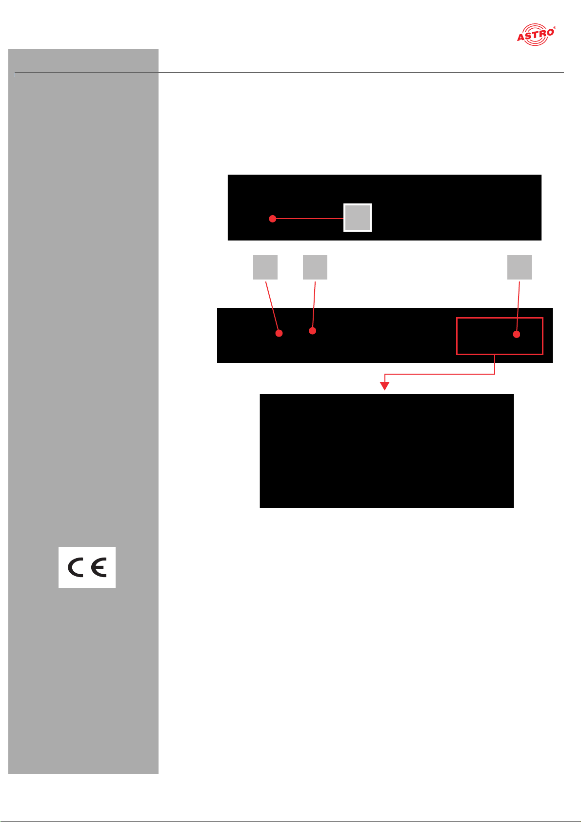
Assembly instructions
WICHTIG: The U 149 S unit may only be installed using guide rails! If the device is only
affixed by the screws in the front panel, this will damage the base unit.
WICHTIG: The outputs of the signal converter must not be operated without connecting a
combining network or terminating impedance!
The device may only be operated and connected in dry rooms. It must not be exposed to spraying
or dripping water, or to similar influences. If condensation appears, wait until the device is
completely dry.
The device may only be assembly on level, non-flammable materials or bases.
The permitted ambient temperature range is 0 - 45 °C (ETS 300 019-1-3 class 3.1).
The device is primarily designed for operation in metallically conductive 19" racks with sufficient
air convection. It should be operated away from heat radiation and other heat sources. The device
my only be installed in rooms in which the permitted ambient temperature can be adhered to, even
under varying climatic conditions. To avoid trapped heat, it must be well ventilated on all sides.
Installing the device in a niche or covering the ventilation openings is not permitted.
No objects may be placed on the device.
The subscriber network must be earthed correctly in accordance with EN 60728-11, and must
remain earthed even when the device is removed. The potential equalisation on the U 100 is
effected via the fastening plates on the device, or via the earth connection on the back of the
device. Devices within hand's reached must be incorporated into the potential equalisation
together. Operating the device without an earth conductor, device earthing or device potential
equalisation is not permitted!
Please notice that the mains voltage, signal sources, etc. must be connected correctly to the
connectors of the device. The local mains voltage must correspond to the mains voltage specified
for the device (see chapter „Technical data“).

page 5
Warranty conditions
Operating manual U 149 - Version 08-2015A
Warranty conditions
The general terms and conditions of ASTRO Strobel GmbH apply. You will find these in the current
catalogue or on the Internet under “www.astro-kom.de”.
Disposal
All of our packaging material (cardboard boxes, inserts, plastic film and bags) is completely recyclable.
Electronic devices must not be disposed of with household waste, but rather – according to DIRECTIVE
2002/96/EC OF THE EUROPEAN PARLIAMENT AND OF THE COUNCIL from January 27, 2003, on
waste electrical and electronic equipment – must be properly disposed of. When it is no longer in use,
please bring the device for disposal to one of the public collection points for this purpose.
ASTRO Strobel is a member of the Elektro system solution for the disposal of packaging materials. Our
contract number is 80395.

Performance description
Operating manual U 149 S - Version 08-2015Apage 6
Performance description
The U 149 S uses four input sockets for reception of up to eight DVB-S2 streams. The two Ethernet
data ports in the U 149 S can then be used to output up to 8 IP video data streams.
To use the devices properly, read the following safety and operating instructions attentively.
The U 149 S plug-in module features the following performance characteristics:
Conversion of up to 8 DVB-S2 input signals into 8 IP gigabit multicast groups
24 streams per height unit possible
Easy configuration using web browser interface
The DVB-S demodulator of the U 149 module additionally features APSK support.

page 7
Device description
Operating manual U 149 - Version 08-2015A
Device description
The delivery consists of the following parts:
U 149 S DVB-S/S2 to IP Streamer
Operating manual
Front:
[1] Ventilation grid
Back:
[2] Mains jack:
[3] Earthing terminals
[4] Connection terminal for
Input signals (RF 1 - 4; F-jack)
Output signals (Data A, B; RJ 45)
Management (A and B; RJ 45)
Figure 1: U 149 S
The U 149 S module features a CE marking. This confirms that the product conforms to the relevant
EC directives and adheres to the requirements specified therein.
4
1
23

Quick start - starting operation of the U 149 S
Operating manual U 149 S - Version 08-2015Apage 8
Quick start - starting operation of the U 149 S
Connecting the U 149 S to a PC or laptop
To be able to configure the U 149 S, you now need to connect the network sockets (Management A )
on the backplane of the device (see figure at left) to your PC or laptop using a network cable.
The device has the IP-address 192.168.1.254.
HINWEIS: Please note that your PC or laptop must be in the same sub-network as the
U 149 S! The sub-network mask of the U 149 S is set to 255.255.255.0 upon delivery. The PC or
laptop which is connected must therefore be assigned an IP address 192.168.1.x.
You can now start the configuration using the web browser user interface.
General information on the structure of the web browser interface
The configuration interface is divided into the following sub-areas:
Figure 4: Structure of the web browser interface
Status line (header) [1]: displays general information on the module.
SW: Software status
HW: Hardware version
Up: Runtime since the system was booted
Time: Date and time
Name, location, contact: corresponds to the settings which were made in the “User settings”
configuration area
Navigation menu [2]: displays the individual configuration areas which can be selected by
clicking the mouse. A detailed description of these areas can be found on the following pages of
this chapter.
Content area [3]: The respective configuration form – depending on the menu item selected – is
displayed here.
HINWEIS: The browser display is not updated automatically. Use the corresponding button
in the menu of your browser to update the display.
1
2
3

page 9
Quick start - starting operation of the U 149 S
Operating manual U 149 - Version 08-2015A
Logging in
To log in, enter the IP address of the U 149 S, which appears in the device display, in the address line
of the browser. The menu page “Status” will then appear. Select the item “Log in” from the navigation
menu at the left. The input mask for the log in should then appear (see figure 6, below). In delivery state,
you must use the following log-in data:
User name: “user” or “admin” (input without inverted commas)
Password: astro
Figure 5: Log in
After logging in, the start page of the U 149 S with all relevant system information will appear. The nav-
igation menu and the log-in status display will appear at the left.
Only one user can be logged into the user interface of the U 149 S at a time. The current user is dis-
played in the column at the left, below the menu.
The device status is indicated by a green or red circle. If a green circle is displayed, the device is oper-
ational. If the circle is red, then a fault has occurred.
A list of current errors is available under the menu item “Active alarms”.
HINWEIS: For reasons of security, you should change the access data valid upon delivery
(user name and password) to prevent unauthorised access!
The procedure is described in the section “Changing user data”.
Changing the IP address
HINWEIS: If you wish to change the IP address, then the settings on the PC must be changed
accordingly.
Start by changing the IP addresses for the management and the data port. To do so, click on the item
“Main” in the menu at the left. You will now see the following table in the content area:
Figure 6: Changing the IP address
You can enter the IP addresses for management ports A and B as well as for data ports A and B in the
“Address” line. Make sure that you activate the ports being used by activating the corresponding radio
button in the line “Active”.
To save your changes, click on the “Submit” button below the last table.
More information on configuring the IP address can be found in the section “Configuring IP interfaces,
IP management and base unit”.

Quick start - starting operation of the U 149 S
Operating manual U 149 S - Version 08-2015Apage 10
The signal flow in the U 149 S
The overview on page 11 shows the possible signal paths for the U 149 S. The specific
signal flow can be divided into the following sub-areas:
One DVB-S2 signal from a satellite which can be preset can be fed in using each of the four F
sockets.
For each of the two front ends in the U148, four reception channels (Ch 1.1 - 1.4 and
Ch 2.1 - 2.4) can be configured. A preferred transponder can be selected from one of the four
respective DVB-S2 reception signals for the reception channel using a drop-down menu in the
web user interface.
The signals from the reception channels are forwarded via a multiplexer (TX Mux) to one of the 8
IP transmitters (TX 1 - TX 8) in total (the overview shows, as an example, the signal from
Ch 1.2 to TX 5, the signal from Ch 1.3 to TX 7 and the signal from Ch 2.2 to TX 8; see the red line
connecting them).
Each of the output signals from the 8 IP transmitters can be forwarded to data port A and/or data
port B respectively.

page 11
Quick start - starting operation of the U 149 S
Operating manual U 149 - Version 08-2015A
Figure 7: The signal flow in the U 149 S
RF 2
DVB-S2 RX
IP TX
Ch1.1 Ch 1.2 Ch 1.3 Ch 1.4 Ch 2.1 Ch 2.2 Ch 2.3 Ch 2.4 Testg.
12345678
RF 1
F-jack
F-jack
... 8 x; Input switch via software dropdown-list
RF 4
RF 3
F-jack
F-jack
TX Mux
Data A
Ethernet
Ethernet
Data B

Quick start - starting operation of the U 149 S
Operating manual U 149 S - Version 08-2015Apage 12
Configuring DVB-S2 satellite receivers
Now start configuring a signal path in the U 149 S. Start by clicking on the item “Input settings” in the
menu in the web browser interface to have the reception settings for the four SAT inputs displayed.
You will now see the following table:
Figure 8: Selecting a reception signal
Select the required satellite (e.g. ASTRA, Eutelsat, etc.) from the “Satellite” drop-down menu. Select
the required polarisation level from the drop-down menu in the “Polarisation/Band” column.
Select a supply voltage for the LNB from the “Voltage” drop-down menu.
If you wish to use a 22 kHz pulse control, activate the radio button “on” in the 22 kHz Tone column.
To save your changes, click on the “Submit” button below the table.
Now click on the “Transponder” item in the main menu at the left to allocate, as an example, a tran-
sponder to the first reception channel (Ch 1.1).
Figure 9: Transponder settings
Select the preferred transponder for channel 1.1 from the drop-down menu.
To save your changes, click on the “Submit” button below the table.

page 13
Quick start - starting operation of the U 149 S
Operating manual U 149 - Version 08-2015A
Checking the transponder status
Now click on the menu item “Trsp. 1.1” in the menu at the left. The following overview will appear:
Figure 10: Displaying the transponder status
The message “OK” should now appear in the “Status” line in the “Transponder 1.1 Settings” table.
Now check the most important parameters in the table which follows, “Channel Status”.
Ensure that you check the values in the “Quality”, “Tuner Level” and “C/N” lines here.

Quick start - starting operation of the U 149 S
Operating manual U 149 S - Version 08-2015Apage 14
Setting the signal routing to the IP transmitters
You can now connect the reception signal to an IP transmitter. To do so, click on the item “TX Mux” in
the web browser interface menu. You will now see the following table:
Figure 11: Signal routing to the IP transmitters
In the switch matrix, click on the radio button which connects the receiver DVB-C/T RX1 to
the IP transmitter IP TX 1.
To save your changes, click on the “Submit” button below the table.
More information about signal routing can be found in the “Menu TX Mux” chapter.
Configuring the IP transmitter
To complete the process, you should now configure and activate the IP transmitter. To do so, click on
the item “IP TX 1” in the web browser interface menu. You will now see the following table:
Figure 12: Configuring the IP transmitter

page 15
Quick start - starting operation of the U 149 S
Operating manual U 149 - Version 08-2015A
In the line “Destination IP Port”, enter the IP address of a reception device (e.g. for one of the signal
converters from the U 1xx series).
In the table at the top, click on the radio button “on” to activate signal transmission to one of the data
ports A or B.
To save your changes, click on the “Submit” button below the table.
More information on setting the IP transmitters can be found in the section “IP TX menu”.
Checking the data transmission rate
Now click on the item “Statistics” in the menu at the left. You will now see the following overview:
Figure 13: IP transmitter statistics
A value > 0 should now appear for the data transmission rate in the line “Transmit” in the “Ethernet
bandwidth” table.
A corresponding value should appear in the line “Total transmit frames generated from IP TX 1” in the
“Ethernet frames” table.
More information about the values in the “Statistics” overview can be found in the section “Statistics
menu”.
Once you have successfully completed all the steps described, then the most important settings re-
quired to decrypt a data stream have been entered in the device.
To ensure error statuses entered in the log book are easy to follow, you should configure a time source.
This can be done under the menu item “Main” in the
“IP Management Settings” table (also see the section “Main Menu”).

“Status” menu
Operating manual U 149 S - Version 08-2015Apage 16
“Status” menu
To have the current settings for the U 149 S displayed, click on the Status item in the menu at the left.
You can now see the overview shown in figure 18:
Figure 14: Status display
The following tables are displayed:
Ethernet status:
Configuration data and status of the Ethernet port
Figure 15: Status display - Ethernet

page 17
“Status” menu
Operating manual U 149 - Version 08-2015A
The values for the following parameters are displayed and configured here respectively in accordance
with the four connections on the backplane of the U 149 S (Data A and Management A, see section
“Device description”).
MAC: MAC address (display value)
Address: IP address (configurable)
Netmask: Net mask (configurable)
Gateway: Gateway IP address (configurable)
Mode: Ethernet mode (display value)
Transmit: Data transmission rate (display value)
Receive: Data reception rate (display value)
Status display of the IP transmitters:
Figure 16: Status display - IP TX channels
The values set for the following parameters are displayed in the table “IP TX Settings” for the four IP
transmitters – for port A and B respectively:
TX IP socket: Destination IP address/port
Encapsulation: Data encapsulation
FEC: Forward error correction
TSID/ONID: Transport stream ID / original network ID
Alias: Alias name
Details on the parameters can be found in the section “Menu IPTX”.

“Status” menu
Operating manual U 149 S - Version 08-2015Apage 18
Status display on temperature, internal voltages and the power module:
Figure 17: Status display - Miscellaneous
The following, general parameters are displayed in the “Miscellaneous” table:
Temperature: Temperature display in °C for the mainboard, as well as DVB-S 1 - 4 and 5 - 8.
Supply 1.2 V: 1.2 V supply voltage
Supply 1.8 V: 1.8 V supply voltage
Supply 2.5 V: 2.5 V supply voltage
Supply 3.3 V: 3.3 V supply voltage
Supply 5.2 V: 5.2 V supply voltage
Supply 13 V: 13 V supply voltage (mainboard only)
Fan: Fan rotation speed
Supply 1.0 V: 1.0 V supply voltage

page 19
“Status” menu
Operating manual U 149 - Version 08-2015A
Memory status:
Figure 18: Status display - System resources
Information on the internal resources of the operating system can be viewed in the “System resources”
table. No settings can be made here.

“Main” menu
Operating manual U 149 S - Version 08-2015Apage 20
“Main” menu
This section explains how to enter general settings for the interfaces and the management of the U 149
S.
Click on the item “Main” in the menu at the left.
Setting the IP interfaces
You can configure IP interfaces and activate or deactivate them using the upper table (“IP interface set-
tings”). The connection type is automatically identified and displayed by the U 149 S (in this case: 1
GBit/s, full duplex).
HINWEIS: In order to make changes in this table, you must be logged in as the adminis-
trator.
Figure 19: Configuring IP interfaces
The following parameters are displayed, and can be configured:
MAC: MAC address of the respective interface
Active: Activate the radio button “on” to activate the interface. Activate the radio button “off” to
deactivate the interface.
Mode: Connection type (identified automatically)
Address: IP address
Subnet: Netmask
Broadcast: Broadcast address
Gateway: Gateway IP (if required)
HINWEIS: When programming the IP addresses, make sure the addresses have not already
been allocated within your network. Address conflicts result in network malfunctions. (Please
set unused parameters to 0.0.0.0.)
To save your changes, click on the “Submit” button below the last table.
Configuring management settings
You can configure the following management settings in the second table (“IP management settings”):
Figure 20: Configuring management settings
Table of contents