Atag VA6111AF User manual

Atag VA6111AF

SOI/TD - PR 2 599 38 70-09

SOI/TD - PR 3 599 38 70-09
TABLE OF CONTENTS:
1ACCESSIBILITY.....................................................................................................................................4
1.1 To access the components from above:.........................................................................................4
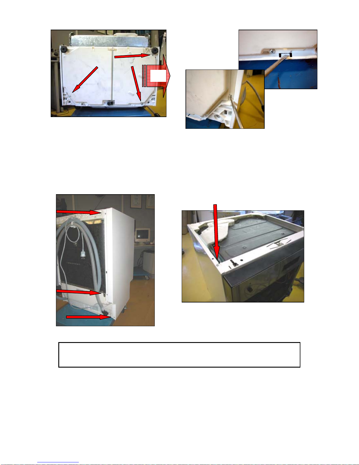
1.2 To access the components housed in the base from the front:......................................................4
1.3 To access the components housed in the base from the lower section:........................................4
1.4 To access components from the side:............................................................................................5
2STRUCTURAL CHARACTERISTICS....................................................................................................6
2.1 Door area ........................................................................................................................................6
2.2 Base area........................................................................................................................................6
2.3 Tub area..........................................................................................................................................7
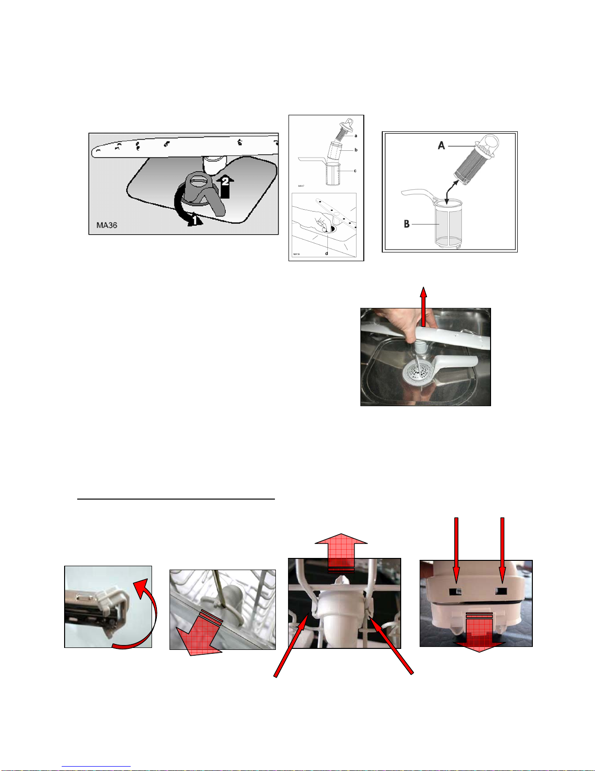
3Open the door to access the following:..................................................................................................7
3.1 Central drain filter............................................................................................................................8
3.2 Large washing filter.........................................................................................................................8
3.3 Lower spray arm .............................................................................................................................8
3.4 Upper spray arm and duct...............................................................................................................8
4Access from above.................................................................................................................................9
4.1 Drying duct/fan (if featured).............................................................................................................9
5Access from the front..............................................................................................................................9
5.1 Sliding guide for upper basket.........................................................................................................9
5.2 Control panel assembly...................................................................................................................9
5.2.1 Timer (electro-mechanic versions)..........................................................................................10
5.2.2 PCB (electronic versions)........................................................................................................10
5.2.3 Door handle.............................................................................................................................10
5.2.4 Pushbutton array.....................................................................................................................10
5.3 External door.................................................................................................................................11
5.4 Beam on floor (fully-integrated versions only, if featured) ............................................................11
5.5 Inner door......................................................................................................................................11
5.6 Latch assembly .............................................................................................................................12
5.7 Integrated dispenser .....................................................................................................................12
5.8 Main electronic board....................................................................................................................12
5.9 Thermostat/temperature and turbidity control sensor...................................................................13
5.10 Regeneration solenoid valve.........................................................................................................13
5.11 Salt sensor (if featured)................................................................................................................14
5.12 Drain pump non-return valve.........................................................................................................14
5.13 Internal feed manifold to the upper spray arm..............................................................................14
6Access from the base...........................................................................................................................15
6.1 Anti-flooding device (if featured) ...................................................................................................15
6.2 Adjustable rear foot (built-in versions only)...................................................................................15
6.3 Sump assembly.............................................................................................................................15
6.4 Water softening system (if featured).............................................................................................16
6.5 Drain pump....................................................................................................................................17
7Access from the sides ..........................................................................................................................18
7.1 Washing motor capacitor ..............................................................................................................18
7.2 External feed manifold to the upper spray arm.............................................................................18
7.3 Supports for upper basket wheels ................................................................................................19
7.4 Lateral front upright.......................................................................................................................19
7.5 Hinges and hinge springs..............................................................................................................19
7.6 Water fill tank.................................................................................................................................20
7.6.1 Models without water softener ................................................................................................20
7.7 Washing motor..............................................................................................................................21
7.8 Level/anti-overflow pressure switches and support......................................................................22
7.9 Tube-enclosed heating element....................................................................................................23
7.10 Fill solenoid valve (if featured) ......................................................................................................23
7.11 Power cable and terminal block with integrated suppressor.........................................................24
7.12 Lower front cross-member............................................................................................................24
7.13 Upper rear cross-member.............................................................................................................24
7.14 Upper front cross-member............................................................................................................24
8Replacing the tub..................................................................................................................................25
9Replacing the base...............................................................................................................................25
Repairs to electrical appliances must be effected by qualified personnel only.
Before accessing internal components, remove the plug from the power socket.

SOI/TD - PR 4 599 38 70-09
1 ACCESSIBILITY
1.1 To access the components from above, first
remove the worktop:
(a) Remove the two screws from the rear section.
(b) Push the top forwards and release.
In case of Built-In dishwashers the worktop is a metal plate. It is
fixed by screws to the structure.
1.2 To access the components housed in the base from the front of the appliance:
(a) Plastic plinth in free-standing appliances: Remove the two front screws which secure the plinth in
position, pull the plinth forwards and release it from the side panels.
(b) Metal plinth in built-in appliances: Remove the two front screws which secure the plinth in position.
foot supports (free-standing versions):
(c) Remove the three screws and detach the foot bracket.
and the lower front panel:
(d) Remove the screws which secure it to the structure; turn and pull out from beneath the lower front
cross-member.
1.3 To access the components housed in the base from the lower section, remove
the bottom panel (if featured) as follows:
(a) Remove the inner filters (see 3.1 and 3.2).
(b) Remove any residual water from the sump by
suction, so that it does not flow into the tub and the
pressure switch tubes, then lay the appliance on its
rear panel.
(c) Unscrew and remove the regulation screw from the
rear foot (built-in versions only).
(d) Remove the screws which secure the bottom panel
to the base).
(e) Release the built-in retaining elements placed on
the right and rear side: and remove the bottom
panel by sliding to the right.
(d )
( c)
(c)
(a) (b)

SOI/TD - PR 5 599 38 70-09
1.4 To access components from the side, remove the relative lateral panel:
(a) First remove the worktop (see 1.1), the plinth and the lower front panel (1.2).
(b) Remove the three rear screws and the upper screw.
(c) Detach the lateral panel from the rear and slide away from the frontal anchor slot.
NB: Before laying the dishwasher on a side panel or on the rear panel
suck the water in the sump, for example by using a syringe, so as the
water does not reach the pressure switch tube or the tub.
(d)
(c)
(e)
(b)

SOI/TD - PR 6 599 38 70-09
2 STRUCTURAL CHARACTERISTICS
The appliance may be considered as consisting of three major assemblies:
DOOR AREA - BASE AREA - TUB AREA
The entire structure is enclosed by a series of removable parts such as the worktop, the door, two lateral
panels, the plinth and the lower front panel. Removal of these parts facilitates access to the internal
components from above, from the front, from the sides and from the base of the appliance.
2.1 Door area
Control panel assembly
External door
Internal door
Hinge
Hinge pin
Lower door seal
Door latch assembly
Integrated dispenser
Electronic board
2.2 Base area
Base
Removable bottom panel (if featured)
Adjustable feet
Foot brackets (free-standing versions)
Adjustable rear foot (central) (built-in and fully-integrated versions)
Main electronic board (if featured)
Anti-flooding device (if featured)
Wash pump capacitor
Integrated terminal block/power cable/suppressor
Washing motor
Tube-enclosed heating element
Drain pump
Drain pump non-return valve
Fill solenoid valve (if featured)
Regeneration solenoid valve (if featured)
Plinth
Counterweight (free-standing versions, if featured)
Water softening system (if featured)
Salt sensor (if featured)
Level pressure switch
Anti-overflow pressure switch

SOI/TD - PR 7 599 38 70-09
2.3 Tub area
Tub
Fitted externally to the tub:
Lateral uprights
Upper rear cross-member
Upper front cross-member
Lower front cross-member
Supports for upper basket wheels
External feed manifold to the upper spray arm
Sump assembly
Thermostat/temperature sensor + turbidity sensor
Water fill tank (short or long)
Drying duct/fan (if featured)
Fitted inside the tub:
Sliding guides for upper basket
Central drain filter
Large washing filter
Lower spray arm
Upper spray arm
Internal feed manifold to the upper spray arm
Upper/lower basket
Cap for water softening system (if featured)
Steam venting ring
3 Open the door to access the following:
1. Guides/wheel supports for upper basket
2. Regulation knob for water softening system (if
featured)
3. Salt reservoir cap (if featured)
4. Integrated detergent/rinse-aid dispenser
5. Control panel assembly
6. Serial number plate
7. Central drain filter
8. Large washing filter
9. Lower spray arm
10. Upper spray arm
11. Upper/lower basket (*)
12. Worktop (free-standing versions only)
(*) When replacing the EASY LIFT drum regulation assemblies, it is advisable to immerse them in hot water
for a few minutes, since they are easier to fit when softened.

SOI/TD - PR 8 599 38 70-09
(a) (c)
(d)(b)
3.1 Central drain filter
(a) From inside the tub, use the lever to rotate the filter assembly about 45° in a counter-clockwise
direction, and remove the assembly from its housing.
(b) Use the central ring to pull the coarse-mesh filter (a or A) and remove from the fine-mesh filter (b, if
featured). Separate the microfilter (c or B) from filter (a or A).
3.2 Large washing filter
(a) After removing the central drain filter (see 3.1), remove the filter (d) from the bottom of the tub.
3.3 Lower spray arm
(a) After removing the lower basket, pull the spray arm
upwards, gripping it by the central hub.
3.4 Upper spray arm and duct
(a) After extracting the upper basket rotate and open the front stops: remove the upper basket from the
guide.
(b) Detach the spray arm from the duct using a very fine-tipped screwdriver. Take care not to damage
the surface of the spray arm.
To inspect the membrane valve fitted to the duct:
(c) Use a tool to release the two rear tabs and completely detach the duct from the basket.
(d) Release the four anchor tabs which secure it to the bottom of the duct and remove the valve support.
NB: While remounting the spray arm, pay attention not to break the plastic hooks.

SOI/TD - PR 9 599 38 70-09
4 Access from above
4.1 Drying duct/fan (if featured)
(a) Remove the worktop (see 1.1)
(b) Raise gently and detach the duct from the water fill tank,
taking care not to damage the sponge sealing element
between the tank and the duct.
(c) From inside the tub, detach the intake ring by pressing the four
hooks.
(d) Carefully lift the duct and remove it.
(e) Detach the connector to the fan.
(f) In order to inspect or replace the drive belt, detach the upper cover from the fan taking care not to
damage the plastic hooks.
5 Access from the front
5.1 Sliding guide for upper basket
(a) Remove the upper basket (see 3.4.a).
(b) Remove the rear arrest by releasing the anchor tab and
pulling upwards.
(c) Remove the guide from the supports.
5.2 Control panel assembly
(a) Remove the door, then remove the six self-tapping screws
which secure the control panel to the inner door.
(b) Supporting the control panel assembly, remove from the
inner door.
(c) Detach the electrical connections.
The following components (if featured) are fitted inside the control
panel and secured by screws or pressure-fitted:
Timer (electromechanical versions)/Power-Display board
Knob assembly
Door handle
Pushbutton array
Pilot lights
I
II
III
(b) (f )
(
c
)
(a)

SOI/TD - PR 10 599 38 70-09
5.2.1 Timer (electro-mechanic versions)
(a) First remove the cover, then the two screws which secure the timer to the control panel.
(b) Pull out the knob/flange assembly.
Important: On certain series of dishwasher with different stylings, it is necessary to remove the knob before
removing the timer.
5.2.2 PCB (electronic versions)
(a) Detach the electrical connections
(b) Use a tool to release the four lateral anchor tabs
(c) Remove the board and its casing from the control panel.
(d) Release the light diffuser, if featured.
5.2.3 Door handle
(a) Use a screwdriver to release the handle pins from the
holes in the control panel.
(b) Remove the counterspring.
5.2.4 Pushbutton array
(a) Remove the two screws which secure the support to the control
panel.
(b) Remove the keys (pressure-fitted to the pushbutton array),
taking care not to damage the anchor tabs.
(c) Detach the pushbutton array from the support and detach the
electrical connections.
(
b
)
(d)

SOI/TD - PR 11 599 38 70-09
5.3 External door
(a) Open the door and remove the six perimetral screws
which secure it to the inner door.
(b) Remove the two lateral screws
(c) Slide the external door forwards and remove
5.4 Beam on floor (fully-integrated versions only, if featured)
(a) Remove the external door (see 5.3).
(b) Remove the screw which secures the plastic support to the door
hinge.
(c) Detach the support from the hinge strut
(d) Remove the wiring tie and disconnect the beamer.
5.5 Inner door
(a) Remove the external door (see 5.3), the control panel (see 5.2), the integrated dispenser (see 5.7) and
the latch assembly (see 5.6).
(b) Open the door and insert a locking pin (e.g. a screw) into the hole in the hinge, so that the door remains
open.
(c) Remove the wiring ties and detach the electrical connections.
(d) Remove the four screws which secure each of the hinges
(e) Lift the inner door and remove.
When replacing the inner door:
During this operation, the hinges must remain open. The locking pin should therefore be removed only after
the inner door has been attached securely to the hinges.
(b) (d)

SOI/TD - PR 12 599 38 70-09
(c)
(b)
5.6 Latch assembly
(a) First, remove the control panel (see 5.2), then the two screws
which secure the latch assembly to the inner door.
(b) To remove the microswitch, lever the anchor tabs open and
extract the switch from its housing.
Important: To replace the latch ferrule and/or the plate: remove the cap which covers the hole and
remove the central screw.
5.7 Integrated dispenser
(a) First, remove the external door (see 5.3) and detach the electrical connections.
(b) Remove the six screws which secure the dispenser to the inner door.
(c) Press the lateral anchor tabs.
(d) Push the dispenser and remove from the interior.
5.8 Main electronic board (if featured)
(a) After removing the plinth and the lower front panel (see 1.2)
(b) By using a tool release the hook which secures the board housing to the plastic support fitted to the
base.
(c) Slide the board housing from its seat, open it and detach the electric connections.
(d)
(a) (b)
(b)

SOI/TD - PR 13 599 38 70-09
(
d
)
(d) When remounting, place the wiring accurately taking
care not to damage the plastic parts and that the wiring
do not come into contact with the warm or live
components which are fitted inside the appliance (for
ex. water fill solenoid, heating element…); ensure that
the board housing is fitted properly to the plastic
support.
5.9 Thermostat/temperature and turbidity control sensor
(a) First, remove the plinth and the lower front panel (see 1.2).
(b) Enlarge the sump hooks and slide the thermostat.
(c) Remove the electrical connectors.
When replacing:
When replacing the thermostat, first lubricate the seal and then position it correctly on the sensor. Insert the
assembled parts taking care to ensure that the seal does not enter the sump.
Important: Check that the anchor tabs return to their original position!
5.10 Regeneration solenoid valve (if featured)
(a) First remove the plinth and the lower front panel (see 1.2).
Important: The softening system will contain a quantity of water.
Before removing the solenoid valve, this water should be removed by suction.
(b) Turn the solenoid valve counter-clockwise until it exits its housing.
(c) Remove the connectors.
When replacing:
When replacing the solenoid valve, lubricate the O-ring and position it correctly on the valve; insert the valve
into the seat and turn clockwise until is locks into position.
(b)

SOI/TD - PR 14 599 38 70-09
5.11 Salt sensor (if featured)
(a) First remove the plinth and the lower front panel (see 1.2).
(b) Detach the electrical connectors from the sensor.
(c) Using a tool release the salt sensor from the water softener and slide it downwards, in some models,
or simply pull it backwards in other models.
5.12 Drain pump non-return valve
(a) First remove the plinth and the lower front panel (see 1.2).
(b) Detach the corrugated tube from the drain pump.
(c) The membrane valve is mounted on the body of the drain
pump.
5.13 Internal feed manifold to the upper spray arm
(a) Working from the rear, remove the nut which secures
the manifold to the tub.
(b) From inside the tub, detach and remove the internal
manifold from the external manifold.
When replacing:
When replacing the manifold, ensure that the seals are correctly
positioned. Tighten the rear screw until it is flush with the pin.

SOI/TD - PR 15 599 38 70-09
(k)
6 Access from the base
NB: Before laying the dishwasher on a side panel or on the rear panel remove the water
in the sump by suction, for example with a syringe, so as it does not reach the pressure
switch tubes or the tub.
6.1 Anti-flooding device (if featured)
(a) Remove the bottom panel (if featured) (see 1.3).
(b) Lift up and release the anchor tab.
(c) To replace the microswitch, lever the tabs open and remove.
6.2 Adjustable rear foot (built-in versions only)
(a) Remove any residual water from the sump by suction
so that it does not flow into the tub and the pressure
switch tubes, then lay the appliance on the rear panel.
(b) Remove the regulation screw from the bottom panel
(see 1.3b).
(c) Using a tool, detach the foot support and slide away
from the base.
6.3 Sump assembly
(a) Remove any residual water from the sump by suction so that it does not flow into the tub and the
pressure switch tubes when the appliance is laid on the rear panel.
(b) Remove the plinth and the lower front panel (see 1.2).
(c) From inside the tub, remove the basket and the lower spray arm (see 3.3).
(d) Remove the central drain filter (see 3.1) and the large washing filter (see 3.2).
(e) Remove the two screws which secure the spray arm support column and remove the column.
(f) Remove the two screws which secure the tub to the sump.
(g) Remove the bottom panel (if featured) (see 1.3).
(h) Remove the anti-flooding device (if featured) (see 6.1)
(b)
(e),(f )

SOI/TD - PR 16 599 38 70-09
(i) Detach all the hoses (to the heating element, the water softener (if featured, see picture on the left),
the washing motor, the drain pump and the pressure switches)
(j) Remove the thermostat and the O-ring (see 5.8)
(k) Detach the drain pump (see 6.5).
(l) Pull the sump out, taking care not to damage the tub seal.
When replacing: When replacing the sump, position the seals correctly and lubricate. The seals should,
preferably, be fitted first to the "male" section of the coupling.
6.4 Water softening system (if featured)
(a) Working from inside the tub, remove the cap of the softening system and the ring located beneath
the cap.
(b) Remove any residual water from the pump by suction so that it does not flow into the tub and the
pressure switch tubes.
(c) Remove the plinth, the lower front panel (see 1.2) and the left lateral panel (see 1.4) and lay the
appliance on the rear panel and remove the cabinet bottom (see 1.3).
(d) Detach the hose which connects the softener to the sump and remove any wiring ties. Detach the
electrical connectors.
(e) Pull the water softener outwards.
When replacing:
When replacing the water softener, position the seal correctly on the lip of the water softener and the seals
on the connection with the water fill tank. Lubricate the seals.
(a)
(i)

SOI/TD - PR 17 599 38 70-09
6.5 Drain pump
(a) Remove any residual water from the sump by
suction so that it does not flow into the tub and the
pressure switch tubes, then lay the appliance on the
rear panel.
(b) First remove the plinth, the lower front panel (see
1.2) and the bottom panel (if featured) (see 1.3).
(c) Working from the front, use pliers to detach the sump hose from the corrugated drain hose; detach
the electrical connectors.
(d) Using a tool, such as a flat-head screwdriver, detach
the two anchor tabs on the body of the pump, one at
a time. Care should be taken to avoid damaging or
breaking the anchor tabs. Remove the pump from its
seat.
When replacing: Mount the sleeve correctly to the sump and
the drain tube. Check for leaks by performing a test cycle.
(c)
(d)

SOI/TD - PR 18 599 38 70-09
7 Access from the sides
RIGHT SIDE VIEW
LEFT SIDE VIEW
7.1 Washing motor capacitor
(a) Remove the worktop (see 1.1), the plinth and the lower
front panel (see 1.2) and the right side (see 1.4).
(b) In some models: remove the protective cap and detach
the electrical connectors pull the capacitor upwards to
remove it from its seat in the base
(c) In some models: Pull the capacitor upwards to remove
it from its seat in the base and detach the electrical
connectors.
7.2 External feed manifold to the upper spray arm
(a) Remove the worktop (see 1.1), the
plinth and the lower front panel (see
1.2) and the right side panel (see 1.4).
(b) Detach the hose to the heating element
(see 7.8.d).
(c) Working from inside the tub, after
removing the upper basket (see 3.4.a),
remove the plastic coupling ring.
(d) Detach the external manifold from the
internal manifold.
When replacing:
When replacing the manifold, position the O-ring correctly on the manifold and lubricate. Replace the
vibration-damping seal between the manifold and the base.
(c) (d)
(b)
( c)

SOI/TD - PR 19 599 38 70-09
7.3 Supports for upper basket wheels
(a) Remove the worktop (see 1.1), the plinth and the lower front
panel (see 1.2), the appropriate lateral panel (see 1.4) and the
upper basket (see 3.4.a).
(b) From outside the tub, remove the two screws which secure
the basket guide wheels in position.
7.4 Lateral front upright
(a) Remove the worktop (see 1.1), the plinth and the lower front panel
(see 1.2), the lower front cross-member (see 7.12) and the
appropriate lateral panel (see 1.4).
(b) Open the door and block in position (see 5.5.b).
(c) Remove the three lateral screws from inside the tub.
(d) From the inside of the tub, remove the four screws which secure the
upper front cross-member in position.
(e) Remove the four screws which secure the cross-member at the front (see 7.14.b)
(f) Remove the two screws which secure the hinge to the inner
door (see 5.5.d)
(g) Detach the earth wire and the hinge strut (see 7.5.e).
(h) Unscrew the adjustable foot and the two screws which secure
the foot support to the base (RH upright only).
(i) Remove the four plastic clip rivets: use a tool to push the central stud of the
rivet from the exterior towards the interior of the tub and remove the assembly
(when refitting, replace the rivet if damaged)
(j) Slide the upper cross-member off the upright.
(k) Remove the cross-member from its seat in the
base.
7.5 Hinges and hinge springs
Proceed as follows to replace each hinge:
(a) Remove the external door (see 5.3), the worktop (see 1.1), the plinth and the
lower front panel (see 1.2) and the appropriate lateral panel (see 1.4).
(b) Use a piece of wire or string to detach the tensioner spring from its
seat on the upright.
(c) Remove the two screws which secure the hinge to the inner door
(see 5.5.d)
(d) Remove the screw which secures the hinge to the upright.
(e) Pull and detach the hinge pin and the earth wire.
When replacing:
Fit the spring to the hinge; then, using a piece of string and a pair of pliers,
attach it to the hook on the upright.
(d)
(c)
(h)
(b)
( j )

SOI/TD - PR 20 599 38 70-09
7.6 Water fill tank
(a) From inside the tub, unscrew the steam venting ring.
(b) Remove the worktop (see 1.1), the plinth and the lower front panel
(see 1.2) and the left-hand lateral panel (see 1.4). Detach the tube to
the fill solenoid.
(c) Detach the fill tank from the drying duct (if featured) (see 4.1).
(d) Pull the fill tank upwards, taking care not to damage the O-rings on
the couplings to the water softener (if featured) and the tub.
When replacing:
When replacing the water fill tank, lubricate the O-
rings and position them correctly on the "male"
part of the coupling.
7.6.1 Models without water softener
(a) From inside the tub, unscrew the steam venting ring.
(b) Remove the worktop (see 1.1), the plinth and the lower front panel (see 1.2) and the left-hand lateral
panel (see 1.4). Detach the tube to the fill solenoid.
(c) Detach the fill tank from the drying duct (if featured) (see 4.1).
(d) Detach the fill tank from the sump assembly.
When replacing:
When replacing the water fill tank, position the condense draining hose correctly, if featured, in
the rear corner of the basement, as shown in the following pictures.
(a)
(d)
Table of contents
Other Atag Dishwasher manuals

Atag
Atag VA 6211TT User manual

Atag
Atag VA3013QT User manual

Atag
Atag VA9811TT User manual

Atag
Atag VA8015QT User manual

Atag
Atag VA6611NT User manual

Atag
Atag VA8215SLR/A02 User manual

Atag
Atag VA4611AT User manual

Atag
Atag VA6111PT User manual

Atag
Atag VA9711RT User manual

Atag
Atag VA 6511NT/A01 User manual