4USA
INTRODUCTION
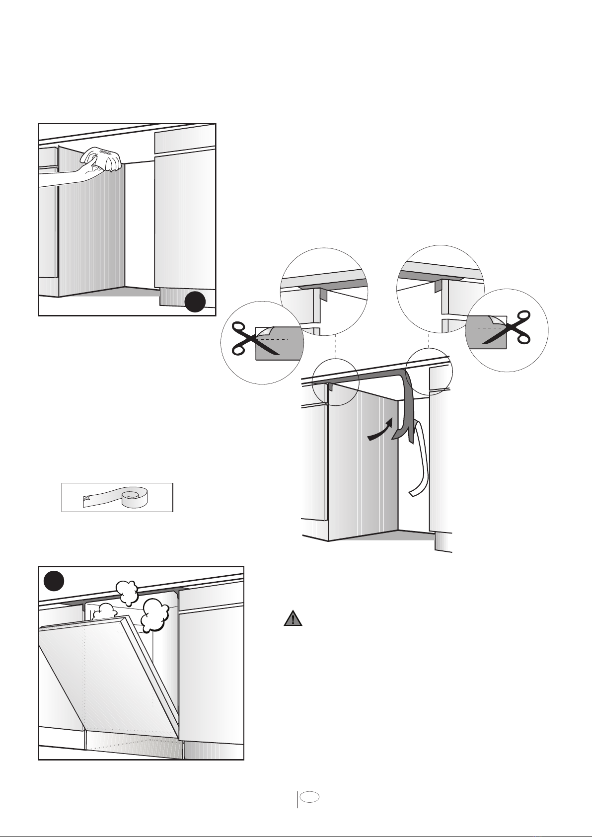
NOTICE :
WARNING CAUTION
Notice
WARNING:
CAUTION:
NOTICE:
1. IMPORTANT SAFETY
INSTRUCTIONS
•
•
•
WARNING
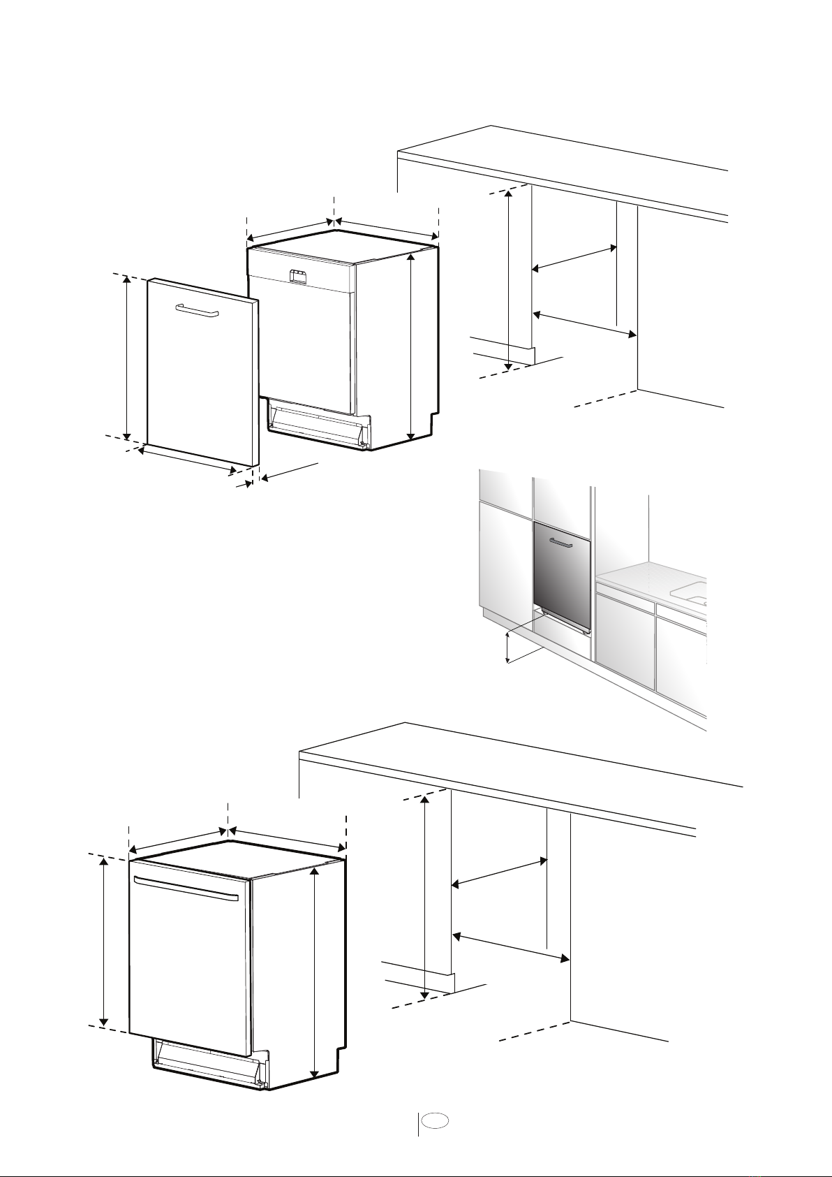
When installing the dishwasher,
follow basic precautions, including
the following:
•
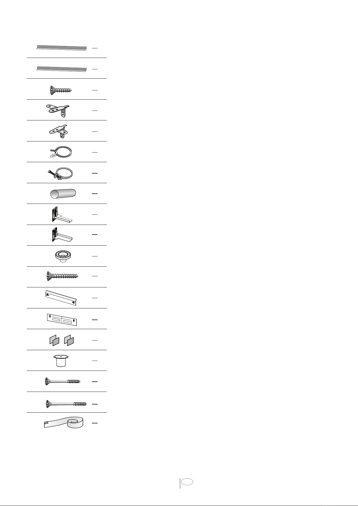
NOTICE :
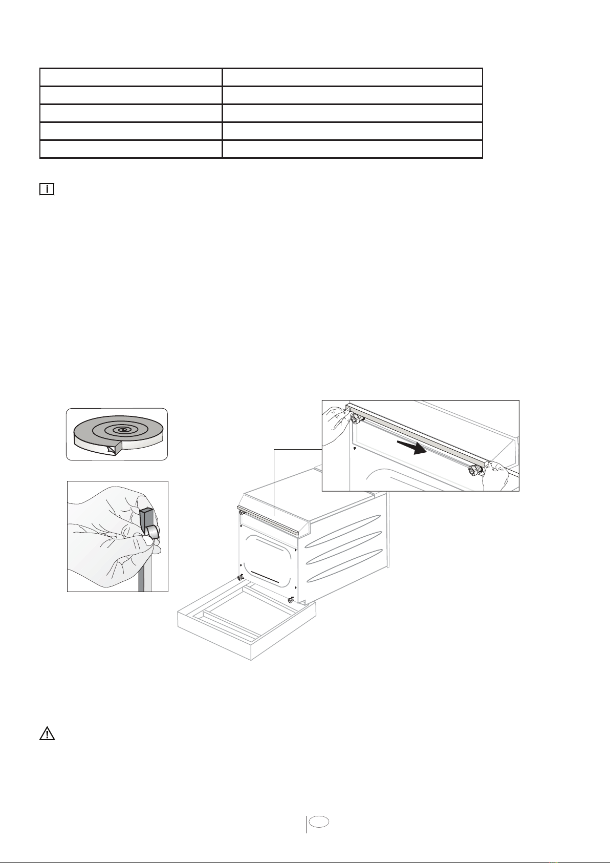
•
•
•
•
•
•
•
•
•
•
•