ATD2 SUB12.D User manual

Active Monitor
PROFESSIONAL AUDIO MONITORING
SUB12.D – SUB15.D
USER MANUAL
ATD2 (Audio Technology Design & Distribution)
6 Rue Bois de Sclessin, B-410 Ougrée, Belgium
Web: www.atd .com Email: info@atd .com

Page

Page 3
TABLE OF CONTENT
1INTRODUCTION ............................................................................................... 6
1.1 This Manual ............................................................................................. 6
1. The Product Concept................................................................................. 6
1.3 Digital Precision ....................................................................................... 6
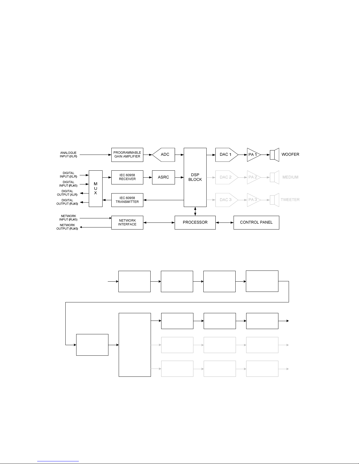
PRODUCT DESCRIPTION ................................................................................... 7
3SUBWOOFER SETUP ......................................................................................... 8
3.1 Connectivity ............................................................................................ 8
3.1.1 Analogue Input..................................................................................... 8
3.1. AES/EBU Input ..................................................................................... 9
3.1.3 AES/EBU Output ................................................................................... 9
3.1.4 FAR Link Network ................................................................................. 9
3. Operation Overview.................................................................................. 9
3.3 Parameter definition ................................................................................11
3.3.1 Subwoofer Volume...............................................................................11
3.3. Digital Channel Selection ......................................................................11
3.3.3 Signal Input Selection ..........................................................................11
3.3.4 Digital Output Selection ........................................................................1
3.3.5 Analogue Full scale selection .................................................................1
3.3.6 Curve selection....................................................................................13
3.3.7 EQ Set selection ..................................................................................14
3.3.8 Subwoofer relative level .......................................................................14
3.3.9 Subwoofer relative delay ......................................................................15
3.3.10 Shelf and Tilts ..................................................................................15
3.3.11 Subwoofer cross-over frequency.........................................................17
3.3.1 Subwoofer Polarity............................................................................17
3.3.13 Subwoofer Phase..............................................................................18
3.3.14 Subwoofer ID...................................................................................18
3.3.15 Network mode .................................................................................19
3.4 Network Operation .................................................................................. 0
3.4.1 Control chaining constraints .................................................................. 0
3.4. Digital audio chaining constraints........................................................... 0
4SYSTEM SETUP ............................................................................................... 1
4.1 Analogue Setup ...................................................................................... 1
4.1.1 Stereo System..................................................................................... 1
4.1. Multi-channel 5.1 System ..................................................................... 1
4. Digital setup ...........................................................................................
4. .1 Stereo .0 System ...............................................................................
4. . Stereo .1 System ............................................................................... 3
4. .3 Multi-channel 5.1 System ..................................................................... 4
4. .4 Multi-channel 6.1 System ..................................................................... 6
5TECHNICAL SPECIFICATIONS ........................................................................... 8

Page 4
RE ISION HISTORY
Date Version Author Change
2006-12-12 1.0 X. Lambrecht Initial revision
2008-12-18 1.1 X. Lambrecht Added Polarity and Phase in the SUB menu
PRODUCT COMPLIANCE
The SUB15.D subwoofer complies with the following specifications:
-EN 55103-1: Product family standard for audio, video, audio-visual and
entertainment apparatus for professional use – Part 1: Emission
-EN 55103-2: Product family standard for audio, video, audio-visual and
entertainment apparatus for professional use – Part : Immunity
-EN 55022: Information technology equipment. Radio disturbance characteristics.
Limits and methods of measurement (Class B)
-EN 55013: Sound and television broadcast receivers and associated equipment.
Radio disturbance characteristics. Limits and methods of measurement
-EN 60065: Safety requirements for main operated electronics and related
apparatus for household and similar general use.
-89/336/EEC European Directive on electromagnetic compatibility (harmonized
standard)

Page 5
SAFETY INSTRUCTIONS
1. Read these instructions.
2. Keep these instructions.
3. Heed all warnings.
4. Follow all instructions.
5. Do not use this apparatus near water.
6. Clean only with a dry cloth.
7. Do not block any ventilation openings. Install in accordance with the manufacturer's instructions.
8. Do not install near any heat sources such as radiators, heat registers, stoves, or other apparatus
(including amplifiers) that produce heat.
9. Protect the power cord from being walked on or pinched particularly at plugs, convenience
receptacles, and the point where they exit from the apparatus.
10. Only use attachments/accessories specified by the manufacturer.
11. Use only with the cart, stand, tripod, bracket, or table specified by the manufacturer, or sold with
the apparatus. When a cart is used, use caution when moving the cart/apparatus combination to
avoid injury from tip-over.
12. Unplug this apparatus during lightning storms or when unused for long periods of time.
13. Refer all servicing to qualified service personnel. Servicing is required when the apparatus has
been damaged in any way, such as power supply cord or plug is damaged, liquid has been spilled
or objects have fallen into the apparatus, the apparatus has been exposed to rain or moisture,
does not operate normally, or has been dropped.
..Warning!..
•To reduce the risk of fire or electrical shock, do not expose this equipment to dripping or splashing
and ensure that no objects filled with liquids, such as coffee cups, are placed on the equipment.
•Use a three wire grounding type line cord like the one supplied with the product.
•This equipment should be installed near the socket outlet and disconnection of the device should
be easily accessible.
•To completely disconnect from AC mains, disconnect the power supply cord from the AC
receptacle.
•The mains plug of the power supply shall remain readily operable.
•Do not install in a confined space.
•Do not open the unit - risk of electric shock inside.
..Service..
There are no user-serviceable parts inside. All service must be performed by qualified personnel.

Page 6
1INTRODUCTION
1.1 This Manual
The latest manual revision is always available for download from www.atd .com. Please
compare to the revision number of the manual (see page 4) available for download from
our web-site and download if newer. The present document will describe how to connect
and setup a speaker system.
1.2 The Product Concept
The FAR Active monitor systems take a quantum leap forward in near-field / mid-field
monitoring and ATD2 is very proud to present these systems. The SUB15.D includes
high quality analogue Class D amplification with the addition of powerful DSPs and CPU.
New possibilities are opened for easy, convenient and central control of both audio and
setup-info via dedicated PC software and remote control. The networking possibilities
will fit nicely into today's applications and can be taken far into the future studio.
The SUB15.D is a Pro Audio near-field / mid-field subwoofer and is excellent for stereo
and surround setups in applications such as Music Recording/Mixing, Post production,
Film, Broadcast, Video-editing etc.
Unlike many rear or front-ported subwoofer that can be very unpractical to set up, the
SUB15.D feature sealed box bass principle design that allows flush mounting, easy
placement in the room and very accurate bass reproduction.
1.3 Digital Precision
The frequency response of the subwoofer of the subwoofer is controlled to a level of
precision only practically obtainable with DSP.
All the filters available in the subwoofer are implemented in the digital domain. This
guarantees a perfect repeatability from subwoofer to subwoofer. They will never vary
with temperature, humidity and aging. It cannot be made more accurate and stable.
As most productions do end up in a digital format these days, the FAR Active monitors
allow direct monitoring of the digital signal. Simply feed the monitors directly with an
AES/EBU signal (IEC60958 compliant).
However, as many studios are today still working with analogue signals for monitoring,
all the FAR Active monitors have, as standard feature, a very high quality analogue input.

Page 7
2PRODUCT DESCRIPTION
The subwoofer box is sealed (infinite baffle principle of work). There are no venting
ports. This brings the following advantages:
-Flush mounting is possible (no rear port)
-No sensitivity to placement with respect to the rear wall (no rear port)
-No “out of phase” interferences between the woofer and a front port
-Cleaner and more accurate restitution in the bass frequencies
There is no such a concept of Master and Slave monitors. All FAR Active monitors have
the same capabilities and features. There are also no special requirements on power ON
and OFF sequences of the monitors. The subwoofers were designed to be “clicks and
plops” free, in any conditions.
The following figure describes the subwoofer synoptic.
Figure 1: Subwoofer Synoptic
The signal processing can be subdivided in multiple functional blocks, as described in the
next figure.
SPEAKER
EQUALIZATION
10 BAND
EQUALIZER
CURVE
FILTERS
SPEAKER
DELAY
3 WAY
XOVER
DRIVER TIME
ALIGNMENT
DRIVER TIME
ALIGNMENT
DRIVER TIME
ALIGNMENT
DRCGAIN
GAIN
GAIN
SPEAKER
LEVEL DRC
DRC
Figure 2: Subwoofer DSP Functional blocks

Page 8
3SUBWOOFER SETUP
All controls, display and connectors are located at the rear of the monitor with the
exception of a front LED that indicates when the subwoofer is powered ON and that also
signal with various types of blinking the network activity, amplifier limiter in service and
hardware faults.
PUSH PUSH
NETWORK
DIGITAL OUT DIGITAL IN ANALOG IN
OUT IN
POWER
Figure 3: Monitor rear
3.1 Connectivity
The subwoofer provides the following connectors:
-XLR Analogue balanced input
-RJ45 FAR Link Network input
-RJ45 FAR Link Network output
-XLR AES/EBU digital input
-XLR AES/EBU digital output
The power input is an IEC connector.
3.1.1 Analogue Input
The monitor has a balanced analogue input on a XLR combo plug. The full scale
sensitivity of the analogue input is selectable via the monitor control menu. It can be set
to +3 dBu, +9 dBu, +15 dBu, + 1 dBu and + 4 dBu.
The standard broadcast full scale input level is +6 dBu with 9 dB headroom. In this case,
the full scale input shall be set to +15 dBu.
The analogue signal is converted to the digital domain by a very high-end converter
(96kHz – 4 bits). It is then treated as the other digital audio streams that can be fed to
the monitor.

Page 9
3.1.2 AES/EBU Input
The monitor has a balanced AES/EBU input on a XLR combo plug. The AES/EBU input is
selectable via the monitor control menu. The AES/EBU input complies with the IEC
60958 standard. audio channels are carried over an IEC60958 stream. The desired
channel is selectable via the monitor control menu.
3.1.3 AES/EBU Output
The monitor has a balanced AES/EBU output on a XLR plug. The AES/EBU output content
is selectable via the monitor control menu. The AES/EBU output complies with the IEC
60958 standard.
The typical use of the AES/EBU output is a signal loop-through to feed other monitors
with the same signal.
3.1.4 FAR Link Network
The FAR Link network allows for streaming of monitor control messages and a pair of
digital audio channels compliant with IEC60958 (AES/EBU like but on another medium).
3.1.4.1 Control Channel
The control channel allows the exchange of messages and data between the monitors
and/or the remote control devices (PC or dedicated remote control).
3.1.4.2 Digital audio input
The monitor can use a CAT5 cable on RJ45 FAR Link TM network plug to receive a digital
audio stream compliant with IEC60958. The Network digital audio input is selectable via
the monitor control menu. audio channels are carried over IEC60958. The desired
channel is selectable via the monitor control menu.
The Network digital audio stream and the AES/EBU stream can run concurrently, making
4 digital audio channels simultaneously available to each monitor.
3.1.4.3 Digital audio output
The monitor can use a CTA5 cable on the RJ45 FAR Link TM network plug to transmit a
digital audio stream compliant with IEC60958. The Network digital audio output content
is selectable via the monitor control menu.
3.2 Operation Overview
The control panel at the subwoofer rear gives access to the basic configuration
parameters of the monitor. The menu items can be selected (displayed on the
alphanumerical screen) using the left and right keys (PREVIOUS / NEXT) while the
parameter value is changed using the up and down keys (+ / -).
The alphanumerical LCD displays the information on lines. The first line shows the
selected parameter and its value. The second line gives the subwoofer status.
Figure 4: Display layout
The input signal field indicates the signal currently used by the monitor. When the
central button is pushed, the monitor is muted and the field shows “Mut”. In nominal
operation, the field can get the following values:
-ANA to indicate that the analogue input is active
-AES to indicate that the AES/EBU input is selected

Page 10
-NET to indicate that the FAR Link network is the signal source
The following picture shows the various subwoofer parameters accessible via the control
panel and their associated value range.
VOLUME: -10.0 dB
ANA▐ FLAT▐ FLAT▐ S8
NEXTPREVIOUS
Digital h.: A(L)
ANA▐ FLAT▐ FLAT▐ S8
A(L)
B(R)
A+B
+
-
NEXTPREVIOUS
Input: Auto Sel
ANA▐ FLAT▐ FLAT▐ S8
AES/EBU
NETwork
Analogue
Auto Sel
+
-
NEXTPREVIOUS
Output: Auto Sel
ANA▐ FLAT▐ FLAT▐ S8
opy I/O
AES/EBU
NETwork
Auto Sel
+
-
NEXTPREVIOUS
AnalogFS: +15 dBu
ANA▐ FLAT▐ FLAT▐ S8
+3 dBu
+9 dBu
+15 dBu
+21 dBu
+24 dBu
+
-
NEXTPREVIOUS
urve: FLAT
ANA▐ FLAT▐ FLAT▐ S8
FLAT
Academy
ar
TV
lub
ustom1
ustom2
ustom3
+
-
NEXTPREVIOUS
EQ Set: FLAT
ANA▐ FLAT▐ FLAT▐ S8
FLAT
Set1
Set2
Set3
Set4
Set5
Set6
Set7
+
-
NEXTPREVIOUS
Delay: 0 cm
ANA▐ FLAT▐ FLAT▐ S8
+
-
LowShelf: 0.0 dB
ANA▐ FLAT▐ FLAT▐ S8
+
-
NEXTPREVIOUS
Tilt 1: 0.0 dB
ANA▐ FLAT▐ FLAT▐ S8
+
-
NEXTPREVIOUS
Tilt 2: 0.0 dB
ANA▐ FLAT▐ FLAT▐ S8
+
-
NEXTPREVIOUS
Tilt 3: 0.0 dB
ANA▐ FLAT▐ FLAT▐ S8
+
-
NEXTPREVIOUS
Xover: 80 Hz
ANA▐ FLAT▐ FLAT▐ S8
+
-
-40.0 dB
-39.5 dB
...
+19.5 dB
+20.0 dB
+
-
Level: 0.0 dB
ANA▐ FLAT▐ FLAT▐ S8
NEXTPREVIOUS
-10.0 dB
-9.5 dB
...
-0.5 dB
0.0 dB
+
-
0 cm
5 cm
...
145 cm
150 cm
-3.0 dB
-2.5 dB
...
+2.5 dB
+3.0 dB
-3.0 dB
-2.5 dB
...
+2.5 dB
+3.0 dB
-3.0 dB
-2.5 dB
...
+2.5 dB
+3.0 dB
-3.0 dB
-2.5 dB
...
+2.5 dB
+3.0 dB
40 Hz
41 Hz
...
159 Hz
160 Hz
NEXTPREVIOUS
ID: 8.SUBWOOFER 1
ANA▐ FLAT▐ FLAT▐ S8
+
-
NEXTPREVIOUS
Net Mode: Slave
ANA▐ FLAT▐ FLAT▐ S8
+
-
8.SUBWOOFER 1
9.SUBWOOFER 2
Slave
Master
NEXTPREVIOUS
Phase: 0 deg.
ANA▐ FLAT▐ FLAT▐ S8
+
-
0 deg.
45 deg.
90 deg.
135 deg.
180 deg.
225 deg.
270 deg.
315 deg.
NEXTPREVIOUS
NEXTPREVIOUS
Polarity: Pos.
ANA▐ FLAT▐ FLAT▐ S8
+
-
Pos.
Neg.
NEXTPREVIOUS
Figure 5: SUB Setup Parameter Overview

Page 11
3.3 Parameter definition
3.3.1 Subwoofer olume
The subwoofer volume is the first menu item. It can range from -40dB to + 0 dB by
steps of 0.5 dB.
Figure 6: olume parameter and values
3.3.2 Digital Channel Selection
The digital channel selector is the second menu item. It allows the user to select the first
channel (A) or second channel (B) of a IEC60958 digital audio stream. In stereo
applications, the left channel is mapped on the A channel and the right channel is
mapped on the B channel. In multi-channel applications, three AES/EBU links are
necessary. The channel mapping is usually defined as follow:
AES/EBU Link Channel A Channel B
Cable 1 Left Right
Cable Center LFE
Cable 3 Surround left Surround right
It is also possible to select the sum of the A and B channels (A+B). This is especially
useful when having a stereo .1 configuration ( speakers plus 1 subwoofer).
Figure 7: Digital channel selection parameter and possible values
3.3.3 Signal Input Selection
The input signal selector is the third menu item. It allows the user to select the input
signal that the monitor will render. As the FAR Active monitor works with both analogue
and digital signals, the user must set a preference. The “Auto Sel” option let the monitor
decide on what to select by default. In this case, the monitor will look for a digital
stream on the AES/EBU input or on the FAR Link network input. While scanning the
digital inputs, the monitor render by default the analogue input. Once a digital stream
compliant with IEC60958 is detected, the monitor switches to the active digital input and
stays locked to it till the stream disappears.
The monitor input can also be forced to one of the three inputs.
Figure 8: Input signal selection parameter and possible values

Page 1
When the selected digital input does not receive a valid digital audio stream, the
separation symbol of the second display line changes its form to an empty square frame
instead of a plain square.
Figure 9: AES input with valid IEC60958 stream
Figure 10: AES input with invalid or not present signal
3.3.4 Digital Output Selection
The digital output signal selector is the forth menu item. It allows the user to select the
digital output signal that the monitor will send on the AES/EBU output and the FAR Link
network output. The monitor can route the digital input signals to the digital outputs in
multiple ways (see section 3.4 for additional details).
Digital output AES/EBU output FAR Link network output
Copy I/O AES/EBU input FAR Link network input
AES/EBU AES/EBU input AES/EBU input
NETwork FAR Link network input FAR Link network input
Auto Sel Active digital input Active digital input
Figure 11: Digital output signal selection parameter and possible values
3.3.5 Analogue Full scale selection
The Analogue full scale selector is the 5th menu item. The balanced input full scale level
can be set to +3 dBu, +9 dBu, +15 dBu, + 1 dBu or + 4 dBu. It is assumed that the
signal is delivered in a symmetrical fashion to the subwoofer. If an asymmetrical signal
or an unbalanced signal must be used, the effective full scale level will become the one
displayed minus 6 dB.
Figure 12: Analogue input full scale selection parameter and possible values
When the analogue input level exceeds the selected full scale level, the separation
symbol of the second display line changes its form to an empty square frame instead of a
plain square.

Page 13
Figure 13: Display behavior when the analogue input level exceeds the selected full scale level
3.3.6 Curve selection
The Curve selector is the 6th menu item. The user can select a preset curve which will
modify the frequency response of the monitor to emulate a given acoustical environment.
There are 7 presets plus the FLAT reference. Each preset filters and name can be
modified by the PC Speaker Control Software (SCS). The Curve selector does only recall
the stored preset.
The factory settings of the monitor provide 4 defined curves by default (Academy, Car,
TV, Club). The “Custom1”, “Custom ” and “Custom3” curves are equivalent to the FLAT
reference curve.
The 4 first letters of the name of the selected curve are permanently displayed on the
second field of the bottom line of the LCD.
Figure 14: Curve selection parameter and possible values (factory default shown)
The curve “Academy” has a low pass filter of the first order (6 dB/Oct) at 8 kHz. It is
meant to emulate the effect of a perforated cinema screen placed in front of the
subwoofers.
The curve CAR simulates the listening in a car environment. A 4 dB boost at 50 Hz and a
dB boost at 3 kHz.

Page 14
The curve “TV” simulates the frequency response of a standard TV set.
The curve CLUB simulates the listening in a night club environment. A dB boost at 60
Hz and a 5 dB boost at 3 kHz.
3.3.7 EQ Set selection
The EQ Set selector is the 7th menu item. The user can select an EQ Set which will
modify the frequency response of the monitor to compensate for room acoustics effects.
There are 7 QE Sets plus the FLAT reference. Each EQ set filters and name can be
modified by the PC Speaker Control Software (SCS). The EQ Set selector does only recall
the stored preset. The factory default for all the 7 EQ Sets is FLAT. The 4 first letters of
the name of the selected EQ set are permanently displayed on the third field of the
bottom line of the LCD.
Figure 15: EQ Set selection parameter and possible values (factory default shown)
3.3.8 Subwoofer relative level
The subwoofer relative level is the 8th menu item. It can range from -10dB to 0 dB by
steps of 0.5 dB. The subwoofer relative level is meant to balance the acoustic power
between multiple speakers in a multi-channel system.

Page 15
Figure 16: Relative subwoofer level parameter and values
3.3.9 Subwoofer relative delay
The subwoofer relative delay is the 9th menu item. It can range from 0 cm to 150 cm by
steps of 5 cm. Speakers relative delay is meant to time align the speakers in a multi-
channel system.
Figure 17: Relative subwoofer delay parameter and values
3.3.10 Shelf and Tilts
The subwoofer features a low shelf filter and 3 tilt filters (parametric EQ filters). The
gain of these filters can be set from -3 dB to +3 dB by steps of 0.5 dB. The corner
frequency and Q or S factor can be modified by the SCS.
Figure 18: Low Shelf gain parameter and possible value
-4
-3
-2
-1
0
1
2
3
4
10 100 1000 10000 100000
Frequency (Hz)
Gain (dB)
Figure 19: Low Shelf frequency response -3dB, -2dB, -1dB, 0dB, +1dB, +2dB and +3 dB gain
(Frequency = 300 Hz and S = 1 are factory default)

Page 16
Figure 20: Tilt 1 gain parameter and possible value
-4
-3
-2
-1
0
1
2
3
4
10 100 1000
Frequency (Hz)
Gain (dB)
Figure 21: Tilt 1 frequency response for -3dB, -2dB, -1dB, 0dB, +1dB, +2dB and +3 dB gain
(Frequency = 35 Hz and Q = 1 are factory default)
Figure 22: Tilt 2 gain parameter and possible value
-4
-3
-2
-1
0
1
2
3
4
10 100 1000
Fre quency (Hz)
Gain (dB)
Figure 23: Tilt 2 frequency response for -3dB, -2dB, -1dB, 0dB, +1dB, +2dB and +3 dB gain
(Frequency = 50 Hz and Q = 1 are factory default)

Page 17
Figure 24: Tilt 3 gain parameter and possible value
-4
-3
-2
-1
0
1
2
3
4
10 100 1000
Frequency (Hz)
Gain (dB)
Figure 25: Tilt 3 frequency response for -3dB, -2dB, -1dB, 0dB, +1dB, +2dB and +3 dB gain values
(Frequency = 75 Hz and Q = 1 are factory default)
3.3.11 Subwoofer cross-over frequency
Figure 26: Cross-over frequency and possible values
The cross-over frequency is the 14th menu item. It sets the frequency of the 4
dB/octave low-pass filter of the subwoofer. The frequency can be set within 40 Hz and
160 Hz by step of 1 Hz. In a multi-channel setup, the cut-off frequency is often 80 Hz.
3.3.12 Subwoofer Polarity
Figure 27: Signal polarity and possible values
The Polarity is the 15th menu item. It sets output signal polarity of the subwoofer. It can
be set to “Pos.”, which means untouched polarity or it can be set to “Neg.”, which means
reversed phase (negative signal over the whole frequency range).

Page 18
3.3.13 Subwoofer Phase
Figure 28: Cross-over Phase and possible values
The absolute phase is the 16th menu item. It defines the phase offset at the cross-over
frequency. The phase offset is implemented by an all-pass filter of the second order.
The value 0 deg. disable the all-pass filter. The phase offset can be set from 0 to 315
deg. by step of 45 deg.
Phase variation
-360
-315
-270
-225
-180
-135
-90
-45
0
10 100 1000 10000
Frequency (Hz)
Phase (deg.)
Figure 29: Phase response for a cross-over frequency of 100 Hz with 45°, 90°, 135°, 180°, 225°,
270° and 315° phase settings
3.3.14 Subwoofer ID
The sub ID is the 17th menu item. It sets the network address and defines the speaker
role in the system. Up to subwoofers can be used concurrently in a network. The sub
ID is permanently displayed in the last field (right end) of the bottom line of the speaker
LCD screen.
Figure 30: Speaker ID parameter and possible value

Page 19
3.3.15 Network mode
The network mode is the 18th and last menu item. It defines the behavior of the
subwoofer on the network.
In Slave mode, a change made on the subwoofer parameter via the subwoofer control
panel is reflected on the network to allow the remote control or the SCS to keep updated
on the speaker system configuration. The other speakers on the network will ignore
these changes.
In Master mode, a change on a subwoofer parameter will be propagated on all the
speakers present on the network. This mode allows one speaker to be used as a remote
control. For instance, muting a speaker set in network master will mute all the speakers
in the network. When a parameter shall be changed on only one sub, make sure that the
sub is in network slave mode.
There can be multiple masters in a network. The network mode status is displayed on
the bottom line of the screen. It is concatenated with the speaker ID. For instance, the
speaker ID 8 in network slave mode will display a S8. The sub ID 9 in network master
mode will display M9.
Figure 31: Network mode parameter and possible value
Not all the speaker parameters are allowed to be broadcasted. The following list gives
the parameters that are affected by the network mode.
•Mute
•Speaker Volume
•Signal Input
•Digital output
•Analogue full scale
•Curve
•EQ set
•Low Shelf gain
•Low Tilt gain
•Mid Tilt gain
•High Tilt gain
•High Shelf gain

Page 0
3.4 Network Operation
The FAR Active Monitors can be connected together via the FAR Link TM network, using
standard CAT5 cables (like the ones used in Ethernet PATCH connections).
WARNING: DO NOT USE ETHERNET CROSS CABLE. They will not work properly.
The network is optional in the use of the monitors. Its primary purpose is to control the
speakers remotely, by using a dedicated remote control or the SCS TM (Speaker Control
Software) running on a Windows OS.
3.4.1 Control chaining constraints
When the network is used for control only, there are no constraints in the sequence of
the speaker connection. The only important thing to verify is that the NETWORK OUT of
a speaker is only connected to the NETWORK IN of another speaker.
WARNING: DO NOT CONNECT NETWORK OUT TO NETWORK OUT.
WARNING: DO NOT CONNECT NETWORK IN TO NETWORK IN.
3.4.2 Digital audio chaining constraints
Due to the signal bridging capabilities of the speakers, the digital audio stream does only
propagate from the INPUT connector (whatever it is) to the OUTPUT connector (whatever
it is). As a consequence, some sequences in the speaker network chaining will not allow
the digital stream to reach its target. Careful attention shall be given to the system
setup (see chapter 4 for more information).
The “Output” speaker parameter defines the signal routing. There are 3 possible
configurations.
Figure 32: Digital signal routing
-“Copy I/O” does replicate on their respective digital outputs the content of the
digital inputs
-“AES/EBU” does copy on the DIGITAL OUT and the NETWORK OUT the content of
the DIGITAL IN
-“NETwork” does copy on the DIGITAL OUT and the NETWORK OUT the content of
the NETWORK IN.
When the system is set to “Auto Sel”, it selects either the “AES/EBU” mode or the
“NETwork” mode, depending on the active input. If the active digital input is
“AES/EBU”, then the output will be “AES/EBU”. If the active digital input is “NETwork”,
then the output will be “NETwork”.
This manual suits for next models
1
Table of contents