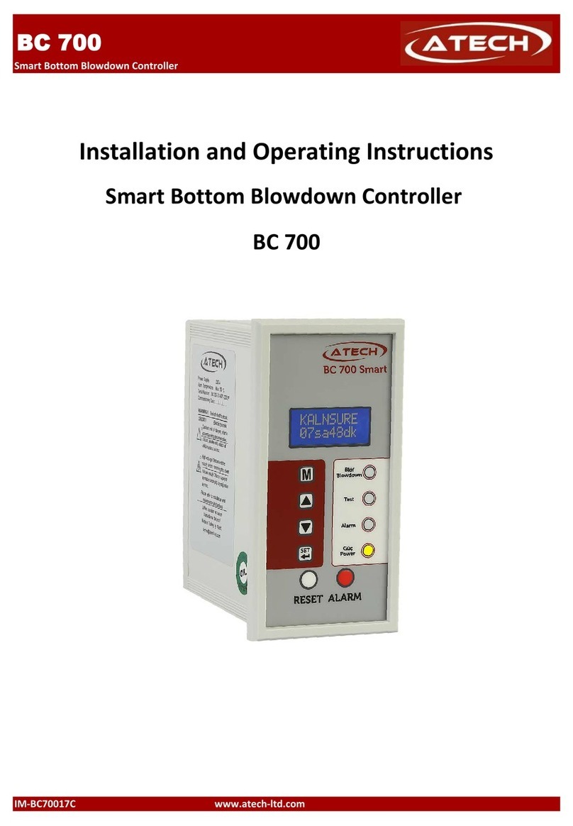
ATECH BC 900 User manual

SMART TDS BLOWDOWN CONTROLLER
IM-BC900-18C
BC 900
www.atech-ltd.com
BC 900
Installation and Operating Instructions
Smart Automatic TDS Blowdown Controller

SMART TDS BLOWDOWN CONTROLLER
1. SAFETY INFORMATIONS 3
2. DESCRIPTION & FUNCTIONS 4
3. TECHNICAL SPECIFICATIONS 6
4. INSTALLATION 6
4.1 Installation 6
4.2 Wiring 7
5. FUNCTIONS and CONFIGURATIONS 9
5.1 Display Definitions and Button Functions 9
5.2 Commissioning - Function Configurations 10
5.2.1 Startup Screen 10
5.2.2 Main Menu 10
5.2.3 Conductivity Set 10
5.2.4 Hysteresis Set 11
5.2.5 Alarm Set 11
5.2.6 Alarm Hysteresis Set 11
5.2.7 Calibration 11
5.2.8 System Mode Auto/Off 12
5.2.9 Valve & Alarm Test 12
5.2.10 Modbus Setup 13
5.2.11 Password 13
5.2.12 Default Settings 13
5.2.13 Software Version 14
6. START UP 14
7. MAINTENANCE 14
IM-BC900-18C Page 2
ATECH ENDÜSTRİYEL ÜRÜNLER SAN. VE TİC. LTD. ŞTİ.
BC 900
CONTENTS
www.atech-ltd.com
Giyim Kent 16. Sok. No: 79 Esenler/İstanbul - Turkey
P : 0.212.438 42 38 F: 0.212.438 42 58

SMART TDS BLOWDOWN CONTROLLER
1. SAFETY INFORMATIONS
Safety!
National and local regulations must be taken into consideration while electrical or mecanical installation.
Warning!
Please make sure to remove the main supply before installation.
Otherwise this may cause damage to the product, personal injuries or even death.
The manufacturer expressly rejects any claims for damage caused by improper installation.
IM-BC900-18C Page 3
BC 900
Installation, commissioning and maintenance of this device must be done by a qualified person in compliance with the
operating instructions. Otherwise device and related equipments may be damaged and personnel may be injured.
www.atech-ltd.com

SMART TDS BLOWDOWN CONTROLLER
2. DESCRIPTION & FUNCTIONS
2.1 Typical applications - BCS 950 & BCS 930 Automatic TDS Blowdown Systems
Smart Automatic TDS Blowdown Controller BC 900, detects the electrical conductivity (TDS - Total Dissolved Solids)
of boiler water via the Conductivity Probe CP 950 or CP 930.
The TDS Blowdown Control Valve BCV 900 opens and closes in response to a high TDS signal from Smart Automatic
TDS Blowdown Controller BC 900. Keeps open until conductivity of the boiler water drops.
If the conductivty is lower than the set point the TDS Blowdown Control Valve BCV 900 remains closed.
Please refer to "BCV 900 Installation and Operation Manual for Automatic TDS Blowdown Control Valve" and
"CP 950 or CP 930 Installation and Operation Manual for Conductivity Probe" for detailed information
before assembly.
1- BC 900 TDS Blowdown Controller 4- BCV 900 TDS Blowdown Control Valve
2- CP 950 or CP 930 Conductivity Probe 5- Valve
3- PC F20 Probe Connection Te 6- Check Valve
IM-BC900-18C Page 4
BC 900
www.atech-ltd.com
Figure 1 Application of Automatic TDS Blowdown Control System / BCS 930 & BCS 950
1
2
3
5
4
6
Drenaja
Buhar Kazanı

SMART TDS BLOWDOWN CONTROLLER
2.2 Typical applications - BCS 920 Automatic TDS Blowdown Systems
Smart Automatic TDS Blowdown Controller BC 900, detects the electrical conductivity (TDS - Total Dissolved Solids)
of boiler water via the Conductivity Probe CP 920.
The TDS Blowdown Control Valve BCV 915 opens and closes in response to a high TDS signal from Smart Automatic
TDS Blowdown Controller BC 900. Keeps open until conductivity of the boiler water drops.
If the conductivty is lower than the set point the TDS Blowdown Control Valve BCV 915 remains closed.
Please refer to "BCV 900 Installation and Operation Manual for Automatic TDS Blowdown Control Valve" and
"CP 920 Installation and Operation Manual for Conductivity Probe" for detailed information before assembly.
1- BC 900 TDS Blowdown Controller 4- TP 920 Temperature Sensor
2- CP 920 Conductivity Probe 5- BCV 915 TDS Blowdown Control Valve
3- PC D32 Probe Chamber 6- SF - Steam Separator
IM-BC900-18C Page 5
Figure 2 Application of Automatic TDS Blowdown Control System / BCS 920
BC 900
www.atech-ltd.com
1
2
5
3
4
Dranage
Steam Generator
6

SMART TDS BLOWDOWN CONTROLLER
3. TECHNICAL SPECIFICATIONS
Enclosure : IP 40 - EN 60529
Maximum ambient temperature : 55 °C
Main supply voltage : 230 V +/– 10 %, 50/60 Hz
115 V +/– 10 %, 50/60 Hz (Opsiyonel)
Frequency : 50 Hz
Maximum power consumption : 3 VA
Material : Plastic
Output signal : 4-20 mA, Relay contacts
Indicators and adjustors : 1 yellow LED for indicating “Power”,
1 green LED for indicating “Blowdown”,
1 red LED for indicating “Test”,
1 red LED for indicating “Alarm”,
1 button “ALARM” for checking alarm,
1 button “RESET” for resetting the alarm,
4 pushbuttons for parameter settings.
Dimensions (height x depth x width) : 144 x 110 x 72 mm
Weight : 0,5 kg
4. INSTALLATION
Installation, commissioning and maintenance of this device must be done by a qualified person in compliance
with the operating instructions.
4.1 Installation to panel
Smart Bottom Blowdown Controller BC 700 is front panel mounting enclosure type and can be applied to the front
panel with two screw clamps supplied.
Allow 20 mm minimum clearance all round the unit for air circulation.
Figure 3 Panel cut out dimensions of Smart Bottom Blowdown Controller BC 900
Please refer to "BCV 900 Installation and Operation Manual for Automatic TDS Blowdown Control Valve" and
"CP 920, CP 930 or CP 950 Installation and Operation Manual for Conductivity Probe" for detailed information
before assembly.
IM-BC900-18C Page 6
BC 900
www.atech-ltd.com

SMART TDS BLOWDOWN CONTROLLER
4.2 Wiring
Wiring between controller and valve actuator, 3x1 mm2cable can be used. Wiring between controller and probe,
5x1 mm2screened (shielded) - (LIYCY) cable can be used. The locations of terminals should not be changed.
If it is considered that the controller has phase connetiction to terminal 11 to terminal 18, then the terminal 1
through 10 of the controller should never be connected to the terminal 11 through terminal 18.
Otherwise, this could cause damage to equipment and even damage to people.
Wiring for BCS 950 & BCS 930 Automatic TDS Blowdown Systems
Figure 4 TDS Blowdown Controller BC 900 electrical connection diagram for BCS 950 & BCS 930 Blowdown Systems
Wiring for BCS 920 Automatic TDS Blowdown Systems
Figure 5 TDS Blowdown Controller BC 900 electrical connection diagram for BCS 920 Blowdown Systems
Note: Relays shown in de-energised state.
If it is considered that the controller has phase connetiction to terminal 11 to terminal 18, then the terminal 1
through 10 of the controller should never be connected to the terminal 11 through terminal 18.
Otherwise, this could cause damage to equipment and even damage to people.
Warning!
At the all phase inputs of the controller, must be used 3A fuse (non-delay type).
IM-BC900-18C Page 7
BC 900
www.atech-ltd.com

SMART TDS BLOWDOWN CONTROLLER
Wiring for CP 920 Conductivity Probe and TP 900 Temperature Probe at BCS 920 TDS Blowdown Systems
Figure 6 Wiring for CP 920 Conductivity Probe and TP 900 Temperature Probe at BC 900 TDS Blowdown Controller
Blue and Red cables at CP 920 Conductivity Probe, shoud be connectted to the BC 900 TDS Blowdown Controller as
three cables thanks to a junction box as showed at Figure 6. Red cables must be connected to therminals 1 and 2,
Also blue cable must be connected to terminal 3 at BC 900 TDS Blowdownd Controller.
Connect screen to earth (blue wire)
TP 920 Temperature Probe's cables must be connected terminal 4 and 5 at BC 900 TDS Blowdownd Controller.
IM-BC900-18C Page 8
BC 900
www.atech-ltd.com

SMART TDS BLOWDOWN CONTROLLER
5. FUNCTION AND CONFIGURATIONS
5.1 Display Definitions and Button Functions.
LCD Screen
Enter or return to main menu
Blowdown Led
Scroll up menus and
increase digits Test Led
Scroll down menus and Alarm Led
decrease digits
Power Led
Enter to functions, submenus
and pass to next digit while
changing a function value
Alarm Reset Buton Alarm Test Buton
button is used to enter main menu or return to main menu.
and buttons are used to scroll down or up function menus in main menu and also is used to change the
numerical values. Those buttons increase or decrease digits.
button is used to enter to functions, submenus and is used to pass the next digit while changing
a functions value.
After change the last digit, button accepts the whole value and returns to main menu.
To return to the main menu without making any changes, press the button
IM-BC900-18C Page 9
BC 900
www.atech-ltd.com

SMART TDS BLOWDOWN CONTROLLER
5.2 . Changing Function Configurations
5.2.1 Startup Screen
When device is powered, the screen likes the figure on the left.
Then conductivty value, will be seen on the screen of the conrtroller
5.2.2 Enter Commissioning
Hold down button for 5 seconds to enter commissioning mode.
To obstruct unauthorized interferences, BC 900 has password protection.
and buttons change each digit and button passes the next digit.
After change the last digit, button accepts the password and if it is true, it
automatically enters the main menu.
5.2.3 Conductivity Set Point
This function is used to set the conductivity value of blowdown.
Set Point is the TDS level at which the valve will open.
Set point should set in accordance with the
boiler manufacturers recommendations.
For example, 6.000 µS/cm value would be appirate
for fire tube / shell steam boilers.
IM-BC900-18C Page 10
www.atech-ltd.com
BC 900

SMART TDS BLOWDOWN CONTROLLER
5.2.4 Hysteresis Set
This function is used to prevent fluctuations of the valve when opening and closing.
When The TDS has increased above the Set Point, and the TDS blowdown valve has
been opened until the TDS drops below the hysteresis of the SP.
It can be selected 5% of set conductivity value.
5.2.5 Alarm Set
Smart Blowdownd Controller BC 900 provides alarm relay output when conductivity
level gets over the value adjusted with this function.
Alarm relay released at this TDS level.
5.2.6 Alarm Hysteresis Set
A damping effect for turbulent conditions.
Normally 5% of alarm figure would be enough.
5.2.7 Calibration
This function is used to define waters conductivity value taken properly from boiler.
When taking water sample from boiler and calibrating the controller, the boiler must
be at operating pressure and temperature. To take more appropriate sample for
measuring and calibrating, Atech Sample Cooler SC 9 is recommended.
For the best accuracy, calibrate the controller with the
TDS as close as possible to the Set Point.
Check the calibration weekly to ensure optimum
performance.
IM-BC900-18C Page 11
BC 900
www.atech-ltd.com

SMART TDS BLOWDOWN CONTROLLER
5.2.8 System Auto / Off
In this mode can be setted as "System Run" that gives An automatic blowdown or
"System Off" that the timer will give no blowdown.
"System Auto"
This mode gives an automatic blowdown, and is the usual
mode selected.
"System Off"
In this mode, the blowdown controller will give no
blowdown. Automatic blowdown is prevented on this boiler.
5.2.9 Tests outputs (Valve and Alarm)
This function is used to test the Blowdown Control Valve BCV 900 and
the alarm function working properly.
With this function, can be test to open or close the
Blowdown Control Valve.
The valve will be open for 2 minutes. Before the test duration
is finished, when button is pressed the valve will be
closed.
With this function, the alarm relay can be testted.
IM-BC900-18C Page 12
BC 900
www.atech-ltd.com

SMART TDS BLOWDOWN CONTROLLER
5.2.10 Modbus Setup (Optional)
This function is used to set Modbus address baud rate and infrared master/slave
configuration, and verifies the number of units on the IR bus
5.2.11 Password
This function is used to change the password of the device.
Press button to enter to function menu.
and buttons increase or decrease digits and
button shift right to the next digit.
After change the last digit, button accepts the new
password.
It is important that if the default pass code is changed that the new value is noted
and kept safe.
Default password 000
New password
5.2.12 Default Settings
If the default settings are needed, "Default Settings" function could be selected from
the menu.
To select "Default Settings", press button for 5 second on this function.
After confirming "Ok" on the screen, will be returned to the
menu. Default settings as below :
Conductivity Set Point : 5.000 uS/cm
Hysteresis : 300 uS/cm
Alarm : 9.500 uS/cm
Alarm Hysteresis : 300 uS/cm
System Run/Off : System Run
IM-BC900-18C Page 13
BC 900
www.atech-ltd.com

SMART TDS BLOWDOWN CONTROLLER
5.2.16 Software Version
Allows the software version to be viewed.
6. COMMISSIONING
• Be sure that all phase and neutral ends are connected to the right terminals on BC 900 Smart Automatic Bottom
Blowdown Controller before energyz.
• Be sure that all function values are adjusted correctly.
• Be sure that all wiring made correctly in compliance with "Automatic TDS Blowdown Valve BCV 900 Installation
and Operating Instructions"
• Be sure that all wiring made correctly in compliance with "Conductivity Probe CP 920, CP 930 or CP 950 Installation
and Operating Instructions"
7. MAINTENANCE
Please make sure to remove the main supply before detach the device.
Warning! Otherwise this may cause damage to the product, personal injuries or even death.
The device is not subject to repair and / or maintenance other than by authorized
service personnel.
When any fault situation occurs or maintenance is necessary, please contact with “
“Atech Service Department”
It is recommended to perform the function tests regularly.
IM-BC900-18C Page 14
BC 900
www.atech-ltd.com

SMART TDS BLOWDOWN CONTROLLER
IM-BC900-18C Page 15
BC 900
www.atech-ltd.com

SMART TDS BLOWDOWN CONTROLLER
IM-BC900-18C
BC 900
www.atech-ltd.com
ATECH ENDÜSTRİYEL ÜRÜNLER SAN. VE TİC. LTD. ŞTİ.
Giyim Kent 16. Sok. No: 79 Esenler/İstanbul - Turkey
P : +.90.212.438 42 38 F: +.90.212.438 42 58
Table of contents
Other ATECH Controllers manuals
Popular Controllers manuals by other brands
PIETRO FIORENTINI
PIETRO FIORENTINI REVAL 182 Technical manual

Neptronic
Neptronic BT100S Specification & installation instructions
DROPSA
DROPSA ADVANCED LUBRICATION CONTROLLER INSTRUCTION AND PRODUCT DATA SHEET
ZIMO
ZIMO MX31FU instruction manual

EINHELL
EINHELL CE-JS 8/1 operating instructions
STORK TRONIC
STORK TRONIC ST710-KPLVR.112S Wiring diagram

Parker
Parker 700-00028-0 Information manual
Asentria
Asentria TeleBoss 830 user manual
BIFFI
BIFFI ALGAS-QA Series Instruction and operation manual
Samson
Samson 2357-31 Mounting and operating instructions
Federal Signal Corporation
Federal Signal Corporation UltraVoice Installation, operation and service manual
ESP Safety
ESP Safety UPES-50D operating manual
