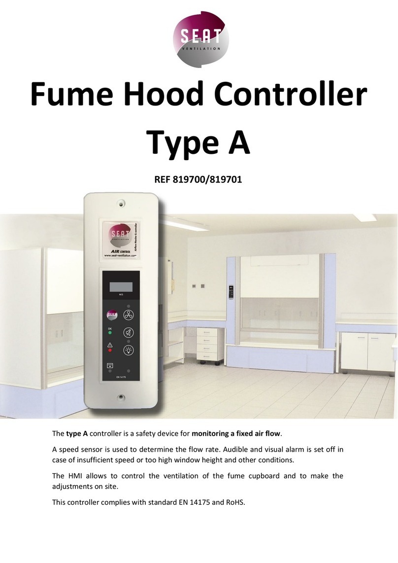
Gavita Master EL2 User manual

Gavita Master Controller EL2
Gavita Master Controller EL2
User manual
Gavita Master Controller EL2


3
User manual
Gavita Master controller EL2
Dear Customer,
Congratulations on the purchase of your Gavita Master controller EL2.
This manual contains all the information necessary to install, use and maintain the
Gavita Master controller EL2. Please read and understand this manual completely
before installing and using the product.
Consult the index at the start of this manual to locate information relevant to you.
In this manual, the Gavita Master controller EL2 will be referred to as the controller.
This is the original manual, keep it in a safe location!

4
Table of contents
1. Introduction 7
1.1. Product description 7
1.2. Glossary of Terminology 8
1.3. Used symbols 8
2. Product specifications 9
2.1. General product information 9
2.2. Technical specifications 9
2.3. Environment 9
2.4. Required tools 9
2.5. Components 10
2.6. Controls 10
2.7. Indications 11
2.8. Connections 12
2.9. Accessories 13
2.10. Compatible ballasts 13
3. Safety guidelines and measures 14
4. Installing the controller 14
4.1. Placing the controller 14
4.2. Installing and connecting the temperature sensor(s) 15
4.2.1. Installing the temperature sensor in “Follow mode” (one room) 16
4.2.2. Installing the temperature sensors in “Inverse mode” (two rooms) 17
4.3. Connecting the controller to the ballasts 18
4.3.1. Connecting the controller to remote ballasts 18
4.3.2. Connecting the controller to complete fixtures 19
4.3.3. Shortening RJ cables 20
4.4. Connecting the controller to External Contactor Modules (ECMs) to
control auxiliary equipment 20
4.4.1. Connecting the signal cable to the controller and the ECM(s) 21
4.4.2. Controlling auxiliary equipment in “Follow mode” (one room) 22
4.4.2.1. Connecting equipment which must be used during lights-on periods 22
4.4.2.2. Connecting equipment which must be used during lights-off periods 23
4.4.3. Controlling auxiliary equipment in “Inverse mode”
(two rooms 12h/12h) 23
4.4.3.1. Connecting equipment which must be used during lights-on periods 24
4.4.3.2. Connecting equipment which must be used during lights-off periods 24
4.5. Connecting a temperature shutdown, sensor failure or
power-off alarm to the controller 24
4.5.1. Connecting an alarm wire to the controller 25
4.6. Connecting the controller to the mains 26

5
5. Preparations before use 27
5.1. Localizing your controller 27
5.1.1. Selecting your default language 27
5.1.2. Switching between 24 hour and AM/PM clock mode and
setting the time 27
5.1.3. Switch temperature units between 0Fahrenheit and 0Celsius 28
5.2. Calibrating the temperature sensor(s) 28
5.3. Change the display mode from the controller output from % to Watts 29
6. Programming and using the controller 30
6.1. Adjust ballast output to change light intensity 31
6.1.1. Control a lamp with a lower power rating then its ballast 31
6.2. Programming a light cycle 31
6.3. Set follow- or inverse mode (aux function) 32
6.4. Set temperature safety settings 33
6.4.1. Setting the auto-dim temperature 33
6.4.2. Setting safety shutdown temperature 34
6.5. Setting the sunrise and sunset period 34
6.6. Activate or deactivate the lights manually or set automatic mode 35
6.7. Resetting the controller to factory settings 35
7. Interpreting controller information 36
7.1. Reading the default screen 36
7.2. Show system time 36
7.3. Interpreting LED signals 36
7.3.1. Green light (22A) 37
7.3.2. Blue light (22C/22D) 37
7.3.3. Red light (22E/22F) 37
7.4. Interpreting display messages 37
7.4.1. Sensor disconnected 37
7.4.2. Sensor failure 37
7.4.3. Controller Overload 37
7.4.4. Auto-dim 38
7.4.5. Temp Alarm 38
7.5. View the software version on the controller 38
8. Maintenance and Repair 39
9. Environment and Disposal 39
10. Warranty 39
11. Appendix I – Overview of all screens on display 40


7
1. Introduction
1.1. Product description
The Gavita Master controller EL2 is a dual channel controller which can
control up to 80 ballasts/lights in climate rooms.
Unlike a switchboard, which switches the power supply of regular ballasts
on and off, the controller can control appropriate Gavita e-series ballasts by
means of a low voltage control signal.
The controller has two channels; a main channel and an auxiliary channel.
Both channels can control a group of up to 40 e-series ballasts.
The controller can be set to activate and deactivate all ballasts connected
toitsimultaneously. In this manual, this mode will be referred to as the
“Follow Mode”.
The controller can also be set to alternate between the main and auxiliary
channel. This means the auxiliary channel and the ballasts connected to it,
are switched off when the main channel and the ballasts connected to it are
switched on and vice versa. An inverted light cycle is intended to be used to
alternate light between two rooms in a 12/12 hour system, to optimize power
utilization. In this manual this mode will be referred to as the “Inverse Mode”.
The ballasts and lights connected to the controller form a significant heat
source within the climate room. If for whatever reason, the climate control
system cannot prevent the temperature from rising in the climate room, the
lights should be dimmed or even shut down to prevent crop damage.
The controller can be connected to either one temperature sensor (in
follow mode) or two temperature sensors (in inverse mode) to sense the
temperature in the climate room(s). The controller offers the possibility to set
the temperature at which it will dim the lights and a temperature at which it
will shut the lights down.
The controller is not meant to replace climate control equipment. Its auto-
dim and shutdown function are primarily meant to prevent crop damage.
Besides controlling up to 80 ballasts, the controller can also control two
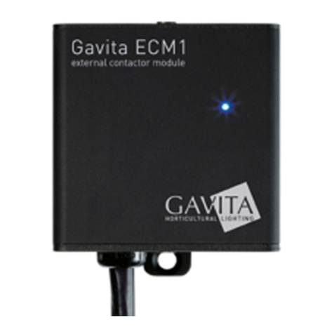
Gavita External Contactor Modules (ECMs). These modules can be used to
switch auxiliary equipment during light on or light off periods (CO2 equipment,
heating, cooling, etc). The ECMs may also be used to switch non-dimmable
supplemental lighting, such as the regular (non e-series) plasma lamps.
Auxiliary equipment is also governed by the controller’s temperature safety
features.
The controller is provided with a set of alarm contacts which may be
connected to a standard alarm installation or cell phone module to provide

8
instant messaging. An alarm will be triggered by temperature shutdown,
sensor failure or power failure.
The controller is equipped with a 16x2 character green OLED display, which
ensures high contrast and clarity in dark and light environments. It provides a
self-explaining menu system with a full text interface for extremely easy and
intuitive use. There is no need to go through a code table to set your controls
or read your statuses. The system is also equipped with LEDs as status
indicators to see the status of your controller at a glance.
The interface language is user selectable: English, Spanish, French, German
and Dutch are standard available.
The Controller uses a low DC voltage to control both ballasts and contactor
modules, making the system safe to install. Cables for plug & play
installation are provided with the controller and the ballasts.
1.2. Glossary of Terminology
ECM External Contactor Module
EL Entry level
Light cycle A 24 hour period in which the lights are activated
and deactivated once
Lights-on period The period of the light cycle in which the lights are
activated
Lights-off period The period of the light cycle in which the lights are
not activated
Follow mode Main and auxiliary channel are switched on and off
simultaneously
Inverse mode Main and auxiliary channel are switched
alternating (one on, one off and vice versa)
Cage clamp Wire clamp
Ballast A ballastis a device intended to ignite and power
HID lamps
Complete fixture A ballast integrated with a reflector and lamp
1.3. Used symbols
The following icons will be used throughout the manual:
Warning! A warning indicates severe damage to the user and/or product may
occur when a procedure is not carried out as described.
Caution! A caution sign indicates problems may occur if a procedure is not
carried out as described.
Note/Example: A note or example provides tips and addition information to
the user.

9
2. Product specifications
2.1. General product information
Product name Master Controller EL2
Product code 60.56.00.xx.xx
Producer Gavita Holland bv
2.2. Technical specifications
Controller dimensions (LxWxH) 127 x 22 x 75 mm
Weight 170 gram
Power supply Adapter: 100V-240V AC 50/60hz -
5V DC (2000mA)
Maximum control voltage 11.5V
Maximum voltage/current alarm
contacts (NO/NC) 13,5V/50mA
Maximum cable length per port 100m (328ft)
Maximum number of ballasts per port 40
Total number of ballasts per controller 80
2.3. Environment
Warning! The product may not be exposed to moisture, condensing humidity,
contamination or dust.
Temperature range 0-35 OC / 32 - 95 OF
Operating humidity (non-condensing) <80%
2.4. Required tools
Task Tool
Mounting controller Screwdriver
Mounting controller Drill
Modify cable length (optional) RJ14 crimp tool

10
2.5. Components
A
IB C D
E F G
I II
A. Gavita Master controller EL2
I. Mounting plate
B. 2x Countersunk screw
C. 2x Plug
D. Manual
E. 120-240V AC - 5V DC power adapter (2000mA)
F. 2x Controller cable (5m/16ft)
I. RJ14 (6P4C) plug (connect to ballasts)
II. RJ9 (4P4C) plug (connect to controller)
G. 2x Temperature sensor with cable (5m/16ft)
2.6. Controls
A EDCB
Key Function
A Quick-key View and adjust output level
B Down Navigate down in menu/decrease value
C Enter Go to menu/confirm
D Up Navigate up in menu/increase value
E Back Navigate back in menu/cancel/reset

11
2.7. Indications
A B
C
D
E
F
For more information on indications go to chapter 7
Indication signal Function
A Power indication
A burning green light indicates controller is active.
A blinking green light indicates a power interruption
has occured during operation.
B Display Displays status, warnings and controller menu.
CLight indication
main A burning blue light indicates the port is active.
A blinking blue light indicates an overload/short
circuit in a cable connected to the port.
Blue light off indicates the port is inactive.
DLight indication
aux
ETemperature
warning main
A burning red light indicates the auto-dim
temperature has been exceeded in the past.
A blinking red light indicates the auto-dim
temperature threshold is currently exceeded. The
corresponding output channels are being dimmed.
A fast blinking red light indicates the shutdown
temperature threshold has been exceeded.
All output channels have been shut down.
FTemperature
warning aux

12
2.8. Connections
A EDCB F G H I
A. 5V DC input
B. 3,5 mm jack main temperature sensor (T1)
C. RJ9 (4P4C) Main port for controlling up to 40 ballasts
D. Cage clamp connector ECM1 (output is active when main channel is on)
E. Cage clamp connector ECM2 (output is active when main channel is off)
F. Cage clamp alarm Normally Open (potential free contact)
G. Cage clamp alarm Normally Closed (potential free contact)
H. RJ9 (4P4C) Auxiliary port for controlling up to 40 ballasts
I. 3,5 mm jack auxiliary temperature sensor (T2)

13
2.9. Accessories
Note: Accessories are not included, they have to be bought separately. Visit
the website of Gavita Holland: www.gavita-holland.com for the latest Gavita
products.
Part Variants Product code
Interconnect cable
(RJ14-RJ14)
2 ft / 0,60 m 60.50.00.08
5 ft / 1.5 m - standard cable 60.50.00.04
8 ft / 2.4 m 60.50.00.09
10 ft / 3.0 m 60.50.00.10
Controller cable
(RJ9-RJ14)
5 ft / 1.5 m 60.50.00.11
16 ft / 5 m - standard cable 60.50.00.12
25 ft / 7.5 m 60.50.00.13
Three-way RJ14 Splitter 60.50.00.01
Power supply Gavita
Master Controller
EL1/EL2
(with 2 m cord,
universal voltage 120-
240 V)
US version 120V 90.02.02.03
UK version 240V 90.02.02.02
EU version 230V 90.02.02.01
AUS version 240V 90.02.02.05
ECM1 External
Contactor Module
(with 10 ft / 3 m cable)
US version 120V 15A 60,57,00,12,20
US version 240V 15A 60,57,00,24,20
UK version 240V 13A 60,57,00,24,11
EU version 230V 16A 60,57,00,23,10
AUS version 240V 10A 60,57,00,24,60
CH version 240V 10A 60,57,00,23,12
ECM controller cable
3m/10 ft 10 ft / 3.0 m standard cable 90.03.01.15
Temperature sensor
(with 5 m cable - 3.5
mm mini jack plug)
16 ft / 5.0 m cable length -
standard 60.50.00.14
2.10. Compatible ballasts
Note: Ballasts are not included, they have to be bought separately. Visit the
website of Gavita Holland: www.gavita-holland.com for the latest Gavita
products.
The Gavita Master controller EL2 is compatible with all Gavita e-series
ballasts.

14
3. Safety guidelines and measures
Warning! Keep the controller away from fire, excessive heat, water, dust and
contamination.
Warning! The Gavita Master controller EL2 may only be used to control
compatible Gavita e-series ballasts. Do not connect the Controller to other
products as this may be dangerous and may cause malfunctions in the
connected equipment. Doing so will void the warranty.
Warning! The ECM channels of the Gavita Master controller EL2 may only be
connected to Gavita ECMs. Do not connect the Controller to other products as
this may lead to malfunctions or damage and can be dangerous. Doing so will
void the warranty.
Warning! Do not open or disassemble the controller, it contains no
serviceable parts. Opening the controller will void its warranty.
4. Installing the controller
4.1. Placing the controller
Warning! The area in which the product is placed must comply with the
conditions specified in paragraph 2.3.
Caution! Only mount the product on a sturdy, solid background.
Note: Use the included plugs for hard surfaces.
• Determine the optimal location for the controller
• Carefully pry the mounting clamp from the controller using a prying tool
or a flat head screwdriver (1) (tape it to prevent damage to the housing).
1 Removing mounting clamp

15
• Hang the controller mounting plate against the desired surface using
one of the a countersunk screws (2A)
• Secure the mounting plate with a second screw (2B)
• Click the controller on the mounting clamp (3).
A
B
2 Hanging the mouniting clamp 3 Clicking the controller on
the clamp
4.2. Installing and connecting the temperature sensor(s)
Warning! The Gavita Master controller is not a climate controller.
Do not use the product to manage the temperature in your climate room.
Caution! Only use Gavita temperature sensors.
Caution! Ensure the controller measures the same temperature as the
climate control system (see paragraph 5.2).
The controller can only be used when it is connected to either one or two
temperature sensors. The controller uses these sensors to monitor the
temperature in the climate room(s). The controller will automatically dim or
shut down the lights if the temperature in a climate room becomes too high.
For more information on temperature safety, consult paragraph 6.4.
The controller must be connected to ONE temperature sensor when the
controller is in “Follow mode”. (see paragraph 4.2.1) The controller must be
connected to TWO temperature sensors if the controller is in “Inverse mode”
(see paragraph 4.2.2).

16
4.2.1. Installing the temperature sensor in “Follow mode” (one room)
Only one of the provided temperature sensors is needed in “Follow mode”.
• Place the provided temperature sensor as close as possible to the
sensor of the existing climate control system, so both sensors will
measure the same temperature (4A)
• Ensure the sensor is covered from the light, as this will disrupt
temperature measurements. Use a hood if necessary (4B).
A template for a hood is included on the last page
• Insert the plug of the temperature sensor into the T1 port (4C)
• The temperature measured by the sensor will be displayed on the
controller display.
Climate control system
A
C
B
4 Placing a temperature sensor in “follow mode”
Note: The displayed temperature may take some time to level out.
Note: If the length of the sensor cable is insufficient to reach the controller,
try to relocate the controller. If this is not possible, the sensor cable may be
lengthened an extra 5 meters by using a standard 3,5 mm jack extension
cable. If the message “sensor removed” appears, the plug of the sensor is not
(fully) plugged in. Plug the sensor in completely.
Note: If the message “sensor failure” appears, the sensor is defect.
Replace the sensor.

17
4.2.2. Installing the temperature sensors in “Inverse mode” (two rooms)
Two temperature sensors are needed in “Inverse mode”.
• Before placing the temperature sensors, determine which controller
channel (main/aux) controls the lights in which room
(“main” room/“aux” room) (5)
• Place one temperature sensor in each room. Ensure both sensors are
placed as close as possible to the temperature sensors of the existing
climate control system (5A)
• Ensure the sensor is covered from the light, as this will disrupt
temperature measurements. (5B) Use a hood if necessary.
A template for a hood is included on the last page
• Insert the plug of the sensor placed in the “main” room (5C) in the T1
input of the controller
• Insert the plug of the sensor placed in the “aux” room (5D) in the T2
input of the controller
• The temperature measured by both sensors will be displayed on the
controller display.
Climate control system
Main Room
A
C D
Main
Room
Aux
Room
Climate control system
Auxilliary Room
B
5 Placing a temperature sensor in “inverse mode”
Note: The displayed temperature may take some time to level out.
Note: If the length of the sensor cable is not long enough to reach the
controller, relocate the controller. If this is not possible, the sensor cable may
be lengthened an extra 5 meters using a standard 3,5 mm jack extension
cable. If the message “sensor removed” appears, the plug of the sensor is not
(fully) plugged in. Plug the sensor in completely.
Note: If the message “sensor failure” appears, the sensor is defect. Replace
the sensor.

18
4.3. Connecting the controller to the ballasts
Warning! The controller may can only be connected to compatible Gavita
e-series remote ballasts and complete fixtures. For a list of compatible
products, consult paragraph 2.10 or go to www.gavita-holland.com.
Note: for more information on shortening RJ cables, consult paragraph 4.3.3.
A group of up to 40 e-series ballasts can be connected to both the main RJ9
port and the auxiliary RJ9 port of the controller. Consult paragraph 4.3.1 to
connect the controller to remote ballasts. Consult paragraph 4.3.2 to connect
the controller to complete fixtures.
4.3.1. Connecting the controller to remote ballasts
Warning! When connecting the fixture to the controller it may ignite. Make
sure either fixture power is disconnected or the controller is switched off.
Warning! Ensure the remote ballasts are connected to their lamps and
reflectors.
• Switch the rotary knob on all Gavita ballasts to “EXT” (external control)
• Plug the RJ9 end of one of the controller cable(s) (6A) into the RJ9 main
port of the controller. If a two room setup is used or if more than 40
ballast have to be connected, plug a second ballast connection cable in
the RJ9 aux port (6B)
• Plug the RJ14 end of the controller cable(s) into one of the two RJ14
ports of the first ballast (6C)
• Interconnect the remote ballast to the next ballast in line using an
interconnect cable with RJ14 plugs (6D). Up to 40 ballasts may be daisy
chained this way.
Max 40 Ballast
Main Channel
Aux Channel
Max 40 Ballast
C
A B
D
6 Connecting the controller to remote ballasts

19
4.3.2. Connecting the controller to complete fixtures
Warning! When connecting the fixture to the controller it may ignite. Make
sure either fixture power is disconnected or the controller is switched off.
Note: A RJ14 splitter and two cables are provided with each complete fixture
since complete fixtures have only one RJ14 port.
• Switch the rotary knob on all Gavita ballasts to “EXT”
• Plug the RJ9 end of one of the provided controller cable into the RJ9
main port of the controller (7A)
• If a two room setup is used or if more than 40 ballast have to be
connected, plug a second controller cable in the RJ9 aux port (7B)
• Plug the RJ14 end of the controller cable(s) (7C) into the input of a RJ14
splitter (7D). Use an interconnect cable to connect one output of the
RJ14 splitter to the RJ14 port of the ballast (7E)
• Use an interconnect cable to connect one output of the RJ14 splitter to
the input of the following RJ14 splitter (7F)
• Repeat this process to connect up to 40 ballasts per group.
Max 40 Ballast
Main Channel
Aux Channel
E
Max 40 Ballast
D C
A B
F
E
F
C
D
7 Connecting the controller to complete fixtures

20
4.3.3. Shortening RJ cables
Note: A RJ14 crimp tool is needed to shorten a RJ cable and install a RJ14
plug!
Note: Don’t remove RJ9 plugs unless you have a RJ9 crimp tool!
Caution! Always follow the instructions provided with the crimp tool!
• Shorten the cable on the desired length
• Strip the outer insulation off the RJ cable (8 mm). Leave the inner
insulation intact!
• Push the four wires into the middle openings of a RJ14 plug. The
orientation of the plug does not matter as long as the wires are entered
in the central four openings (8A).
Caution! If the wires are not inserted in the middle of the plug, the wires
will short circuit, when plugged into a ballast or complete fixture, causing a
controller overload (8B, see also paragraph 7.4.3).
• Crimp the RJ 14 plug on the RJ wire.
A B
8 Wiring a RJ14 plug
4.4. Connecting the controller to External Contactor Modules
(ECMs) to control auxiliary equipment
Warning! ECMs can handle equipment with a resistive load (AC1) up to 16A.
The maximum allowable current can be limited by local type of plugs
(e.g. UK = 13A). Higher currents may be supported by using ECMs to trigger
heavier contactors.
Warning! To prevent over-current, always determine the maximum allowable
current for your (local) cabling before connecting a load to the ECM.
Warning! Never connect the cage clamps of the ECM to any other device than
the Gavita EL2 controller.
Warning! Never connect more then one ECM to each set of cage clamps of
the controller.
Table of contents
Other Gavita Controllers manuals
Popular Controllers manuals by other brands
EUCHIPS
EUCHIPS EULP50D-2HMC-0 quick start guide
Schaudt
Schaudt LRM 1218 operating instructions
Eltorque
Eltorque EQS 1374 user manual
Flowserve
Flowserve Logix 510si Installation, operation & maintenance instructions
Hardy
Hardy HI 4050 user guide
Digital Equipment
Digital Equipment DEC WANcontroller 622 Problem Solving
