sparkfun Qwiic Flex Glove Controller SEN-14666 Technical document

Qwiic Flex Glove Controller Hookup Guide
Introduction
Flex sensors are great for telling how bent something is in a project, but we’ve been running into issues with
durability when using them in wearable applications like gloves. The Qwiic Flex Glove Controller isolates the weak
point to allow for more permanent flex sensor applications. The board has an onboard ADS1015 ADC to I C so we
can get a whole bunch of analog inputs without touching our microcontroller’s ADC pins.
2
SparkFun Qwiic Flex Glove Controller
SEN-14666
Y
O
U
R
A
C
C
O
U
N
T
L
O
G
I
N
R
E
G
I
S
T
E
R

In this hookup guide, we’ll figure out how to pull values from our fingers as well as calibrate the sensor for our
range of motion. We’ll also cover recommended placement and installation to implement these into gloves.
Required Materials
To get started, you’ll need a microcontroller to, well, control everything.
Now to get into the Qwiic ecosystem, the key will be one of the following Qwiic shields to match your preference of
microcontroller:
SparkFun RedBoard - Programmed with
Arduino
DEV-13975
SparkFun ESP32 Thing
DEV-13907
Raspberry Pi 3
DEV-13825
Particle Photon (Headers)
WRL-13774

You will also need a Qwiic cable to connect the shield to your sensor, choose a length that suits your needs.
SparkFun Qwiic Shield for Arduino
DEV-14352
SparkFun Qwiic HAT for Raspberry Pi
DEV-14459
SparkFun Qwiic Shield for Photon
DEV-14477
Qwiic Cable - 100mm
PRT-14427
Qwiic Cable - 200mm
PRT-14428
Qwiic Cable - 500mm
PRT-14429
Qwiic Cable - 50mm
PRT-14426

If you don’t have a sewing needle, we’d recommend grabbing one if you’re trying to add these flex sensors to
some gloves.
Suggested Reading
If you aren’t familiar with our new Qwiic system, we recommend checking out our overview:
WHAT IS QWIIC?
We would also recommend taking a look at the hookup guide for the Qwiic Shield if you haven’t already. Brushing
up on your skills in I C is also recommended, as all Qwiic sensors are I C.
Needle Set
TOL-10405
2 2
I2C
An introduction to I2C, one of the main embedded
communications protocols in use today.
Serial Terminal Basics
This tutorial will show you how to communicate with
your serial devices using a variety of terminal emulator
applications.

You’ll also most likely want to sew these boards into a wearable project, so if you’ve never picked up a needle and
thread before, we’d recommend checking out a how-to on hand sewing.
Hardware Overview
Let’s look over a few characteristics of the ADS1015 so we know a bit more about how our glove controller
behaves.
Characteristic Range
Operating Voltage 2.0V - 5.5V
Operating Temperature -40°C - 125°C
Resolution 12 bit
Sample Rate 128 Hz - 3.3 kHz
Current Consumption 150 µA (Typ.)
I C Address 0x48 (default), 0x49, 0x4A, 0x4B
Pins
The characteristics of the available pins on the magnetometer are outlined in the table below.
Pin
Label
Pin
Function
Input/Output Notes
3.3V Power
Supply
Input Should be between 2.2V - 3.6V
GND Ground Input 0V/common voltage.
SDA I C Data
Signal
Bi-directional Bi-directional data line. Voltage should not exceed power supply
(e.g. 3.3V).
SCL I C Clock
Signal
Input Master-controlled clock signal. Voltage should not exceed power
supply (e.g. 3.3V).
Optional Features
Qwiic Shield for Arduino & Photon Hookup
Guide
Get started with our Qwiic ecosystem with the Qwiic
shield for Arduino or Photon.
2
2
2

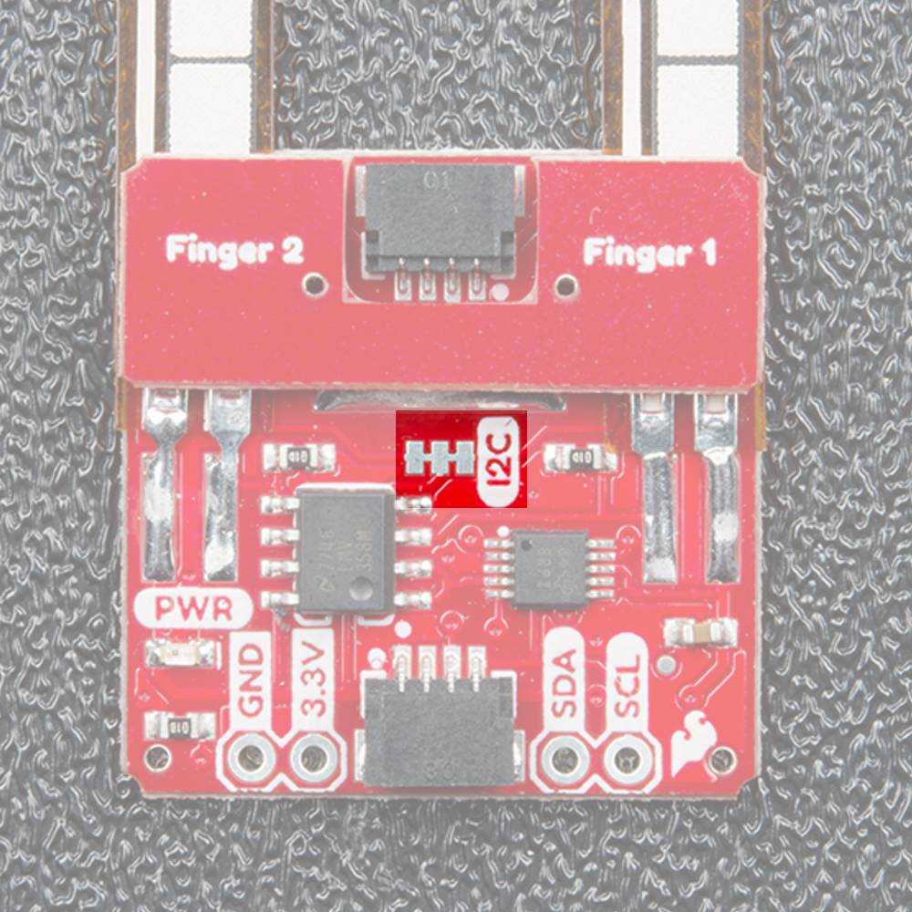
The Qwiic Flex Glove controller has onboard I C pull up resistors, which can be removed by removing the solder
from the jumper highlighted below. Only remove this solder if you are using your own pullups on the I C lines.
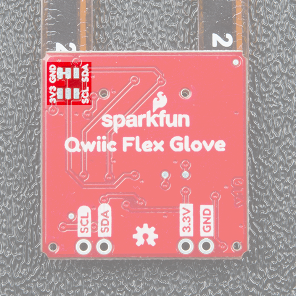
The I C address of the board can be changed using the jumpers on the back of the board. The address selection
pin is connected to the center pad of each jumper, the below table shows the addresses available when the
address selection pin is tied to each of the 4 available pads.
Pin Address
GND 0x48 (Default)
VCC 0x49
SDA 0x4A
SCL 0x4B
The location of the jumpers is shown in the below image.
2
2
2

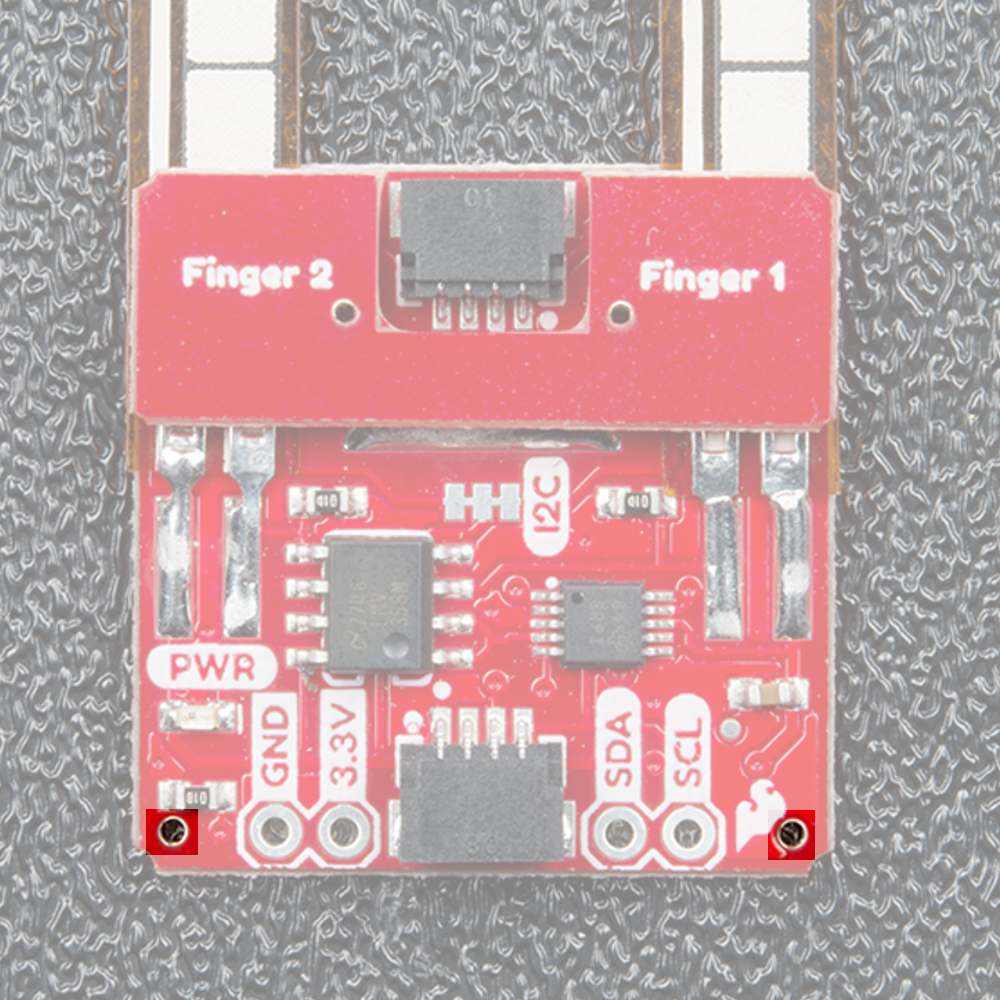
The holes in the bottom corners of the board are used for sewing the board into the gloves of your choice.
Make sure you don’t crease the flex sensors as this will break the sensor!
Hardware Assembly
If you haven’t yet assembled your Qwiic Shield, now would be the time to head on over to that tutorial.
QWIIC SHIELD FOR ARDUINO PHOTON HOOKUP GUIDE
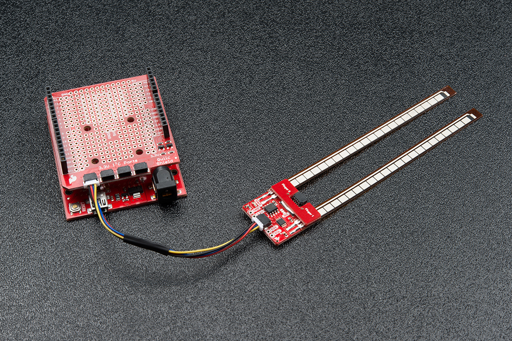
With the shield assembled, SparkFun’s new Qwiic environment means that connecting the sensor could not be
easier. Just plug one end of the Qwiic cable into the Flex Glove Controller breakout, the other into the Qwiic Shield
of your choice and you’ll be ready to upload a sketch and figure out how bent your fingers are. It seems like it’s too
easy to use, but that’s why we made it that way!
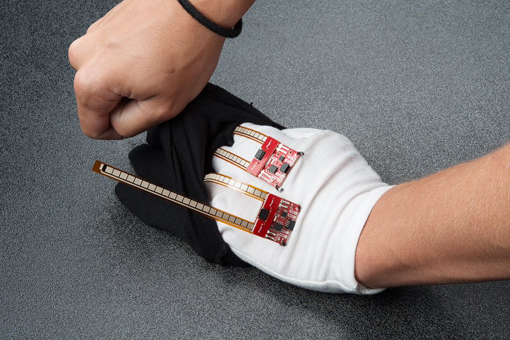
You may want to integrate this board into some gloves, after all, that’s what it was originally designed for. If you’re
looking to get sensors on 8 fingers, you’ll need 4 glove boards, and if you have 4 boards on the same I C bus,
you’ll need to use every address available to the ADS1015. So get started by changing the addresses of your
boards so no two boards share the same address.
Now we want to attach our boards to our gloves. We’ve found it best to sandwich the board between two layers of
gloves to keep the sensor flush with the finger. To accomplish this, we’ll sew the board to the outer layer of the
inner glove. First, lay the glove out flat and place the board on the glove so that the ends of the flex sensors reach
the tips of the fingers.
s

Once you have the sensor laid out on the glove, take a marker and mark the point where the sewing hole touches
the glove.
Now simply sew the points to the available mounting holes on the sensor, The finished product should look like the
below glove.
Now it’s time to hide the circuitry under a second glove. Go ahead and put the just the fingers of the second glove
on, then slip the flex sensor down the gap between the the two layers of fabric. Sensors are shown at various
states of this process in the image below.

Now just plug Qwiic cables to connect both boards together, then plug one board into your microcontroller so we
can get readings from the glove.
Library Overview
Note: This example assumes you are using the latest version of the Arduino IDE on your desktop. If this is
your first time using Arduino, please review our tutorial on installing the Arduino IDE. If you have not
previously installed an Arduino library, please check out our installation guide.
Before we get into getting data from our flex sensors, let’s look at the available functions in the library. We’ve
written a library to control the flex sensors. You can snag this library through the Arduino Library Manager. Search
for SparkFun ADS1015 Arduino Library and you should be able to install the latest version. If you prefer
manually downloading the libraries from the GitHub repository, you can grab them here:
DOWNLOAD THE SPARKFUN ADS1015 ARDUINO LIBRARY (ZIP)
Let’s get started by looking at the functions that set up the flex controller.
Setup and Settings
boolean begin(uint8_t deviceAddress = BNO080_DEFAULT_ADDRESS, TwoWire &wirePort = Wire); — By
default use the default I2C address and use Wire port. Otherwise, pass in a custom I C address and wire
port.
uint16_t getAnalogData(uint8_t channel); — Returns the uncalibrated analog value from the sensor.
float getScaledAnalogData(uint8_t channel); — Returns a value between 0 and 1 based on calibration.
Won’t work properly without first running calibrate()
void calibrate(); — Used to calibrate the sensor and map the flexible range to values given by the user.
While running calibration, simply flex each sensor to the minimum and maximum that it will be used in your
project.
void setMode(uint16_t mode); — Set mode of the sensor. Mode 0 is continuous read mode, mode 1 is
single-shot
uint16_t getMode(); — Get’s the read mode of the ADS1015.
getCalibration(uint8_t channel, bool hiLo) — Get the high or low calibration value for a certain
channel. if hiLo is true, getCalibration() will return the high calibration for the given channel.
setCalibration(uint8_t channel, bool hiLo, uint16_t value) — Sets the high or low calibration value
of a channel without using the automatic calibration function. Allows for manual calibration.
2
https://github.com/sparkfun/SparkFun_ADS1015_Arduino_Library/archive/master.zip

resetCalibration() — Resets the calibration to 0.
void setGain(uint16_t gain); — Pass in different values for different gains
uint16_t getGain(); — Get’s the gain of the ADS1015. This will return 16-bit hex value. The values and
their corresponding gains are listed below.
0x0E00 : ± 0.256V
0X0000 : ± 6.144V
0X0200 : ± 4.096V
0X0400 : ± 2.048V
0X0600 : ± 1.024V
0X0800 : ± 0.512V
0X0A00 : ± 0.256V
void setSampleRate(uint16_t sampleRate); — Sets the sample rate for the ADS1015, pass in the below
16-bit values to change to the corresponding sample rate.
0X0000 : 128 Hz
0X0020 : 250 Hz
0X0040 : 490 Hz
0X0060 : 920 Hz
0X0080 : 1600 Hz
0X00A0 : 2400 Hz
0X00C0 : 3300 Hz
uint16_t getSampleRate(); — Returns the sample rate according to the above list of sample rates.
Example Code
Now that we know how our library works, let’s go ahead and get started pulling values from our flex sensors.
Example 1 - Basic Readings
To get started with the first example, open up File > Examples > SparkFun ADS1015 Arduino Library >
Example1_BasicReadings. In this example, we begin by creating an ADS1015 object called fingerSensor and
then initializing our sensor object in the setup() loop. We then get the values from each finger by looping through
and reading each channel on the ADS1015. The code for this is shown below.

#include <SparkFun_ADS1015_Arduino_Library.h>
ADS1015 fingerSensor;
void setup() {
Wire.begin();
Serial.begin(115200);
if (fingerSensor.begin(Wire, 100000, ADS1015_ADDRESS_GND) == false) {
Serial.println("Device not found. Check wiring.");
while (1);
}
}
void loop() {
uint16_t data;
for (int finger = 0; finger < 2; finger++) {
data = fingerSensor.getAnalogData(finger);
Serial.print(finger);
Serial.print(": ");
Serial.print(data);
Serial.print(",");
}
Serial.println();
}
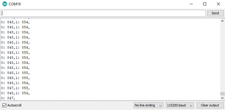
Uploading this sketch and opening the Serial Monitor to 115200 bps will yield an output somewhat like the below
image.
Single Sensor Output - click the image for a closer look
Example 2 - Setup hand
In this example, we’ll see how to setup an entire hand of flex sensors. To get started with this example, open up
File > Examples > SparkFun ADS1015 Arduino Library > Example2_SetupHand. In this example, we create
two ADS1015 objects, naming them indexSensor and pinkySensor to correspond with their locations on the
glove. We also create an array with 4 spots to hold the data for the hand called hand . We then populate hand
with values from each sensor. The code that accomplishes this is shown below.

#include <SparkFun_ADS1015_Arduino_Library.h>
ADS1015 pinkySensor;
ADS1015 indexSensor;
uint16_t hand[4] = {0, 0, 0, 0};
void setup() {
Wire.begin();
Serial.begin(115200);
if (pinkySensor.begin(Wire, 100000, ADS1015_ADDRESS_SDA) == false) {
Serial.println("Pinky not found. Check wiring.");
while (1);
}
if (indexSensor.begin(Wire, 100000, ADS1015_ADDRESS_GND) == false) {
Serial.println("Index not found. Check wiring.");
while (1);
}
}
void loop() {
uint16_t data;
for (int finger = 0; finger < 2; finger++) {
hand[finger] = indexSensor.getAnalogData(finger);
hand[finger + 2] = pinkySensor.getAnalogData(finger);
}
for (int finger = 0; finger < 4; finger++)
{
Serial.print(finger);
Serial.print(": ");
Serial.print(hand[finger]);
Serial.print(" ");
}
Serial.println();
}
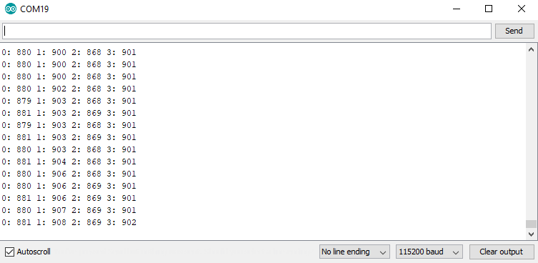
Uploading this sketch and opening the Serial Monitor to 115200 bps will yield an output somewhat like the below
image.
Full Glove Output - click the image for a closer look
Example 3 - Calibration

The second example will show us how to calibrate our flex sensor so we get 0 when our finger is closed and 1
when it is open. To get started, open up File > Examples > SparkFun ADS1015 Arduino Library >
Example3_Calibration. In this example we will calibrate our sensor’s maximum and minimum values in order to
find the range for our sensor.

#include <SparkFun_ADS1015_Arduino_Library.h>
#include <Wire.h>
ADS1015 fingerSensor;
void setup() {
Wire.begin();
Serial.begin(115200);
if (fingerSensor.begin(Wire, 100000, ADS1015_ADDRESS_GND) == false) {
Serial.println("Device not found. Check wiring.");
while (1);
}
Serial.println("Calibrating, send 'e' when finished");
}
void loop() {
uint8_t incoming;
do
{
fingerSensor.calibrate();
if(Serial.available())
{
incoming = Serial.read();
}
} while (incoming != 'e');
Serial.println("Calibrated");
for (int channel; channel < 2; channel++)
{
Serial.print("Channel ");
Serial.print(channel);
Serial.print(": ");
for (int hiLo = 0; hiLo < 2; hiLo++)
{
switch (hiLo)
{
case 0:
Serial.print("Low: ");
Serial.print(fingerSensor.getCalibration(channel, hiLo));
break;
case 1:
Serial.print(" High: ");
Serial.print(fingerSensor.getCalibration(channel, hiLo));
break;
}
}
Serial.println();
}
}

The sensor is initialized in the same manner as the first example, then our loop() begins calibrating the sensors.
To calibrate the sensors, simply flex them to their maximum and minimum bend radii, then send an e over the
Serial Monitor when you’re finished. This will save the current calibration and show you the values that have been
saved. Uploading this sketch and opening the Serial Monitor to 115200 bps will yield an output somewhat like the
below image once you’ve sent e and saved the calibration.
Calibration Output - click the image for a closer look
Example 4 - Calibrated Hand
You don’t necessarily want to calibrate your hand every single time you put on a glove with the flex controllers built
in, so let’s figure out how to manually set our calibration if we know it already. To get started, open up File >
Examples > SparkFun ADS1015 Arduino Library > Example4_ManualCalibration. We can see in the
preamble to our code that we have an array of all of our calibration values, which were obtained using the previous
example sketch. We then use a loop in the setup function along with our setCalibration() function to set the
individual calibration values. The code for this is shown below.

#include <SparkFun_ADS1015_Arduino_Library.h>
#include <Wire.h>
ADS1015 pinkySensor;
ADS1015 indexSensor;
float hand[4] = {0, 0, 0, 0};
uint16_t handCalibration[4][2] = {
//{hi , low}
{722, 1080},//index
{600, 980},//middle
{680, 900},//ring
{736, 907} //pinky
};
void setup() {
Wire.begin();
Serial.begin(115200);
//Begin our finger sensors, change addresses as needed.
if (pinkySensor.begin(Wire, 100000, ADS1015_ADDRESS_SDA) == false)
{
Serial.println("Pinky not found. Check wiring.");
while (1);
}
if (indexSensor.begin(Wire, 100000, ADS1015_ADDRESS_GND) == false)
{
Serial.println("Index not found. Check wiring.");
while (1);
}
//Set the calibration values for the hand.
for (int channel; channel < 2; channel++)
{
for (int hiLo = 0; hiLo < 2; hiLo++)
{
indexSensor.setCalibration(channel, hiLo, handCalibration[channel][hiLo]);
pinkySensor.setCalibration(channel, hiLo, handCalibration[channel + 2][hiLo]);
}
Serial.println();
}
}
void loop() {
for (int channel = 0; channel < 2; channel++)
{
//Keep in mind that getScaledAnalogData returns a float
hand[channel] = indexSensor.getScaledAnalogData(channel);
hand[channel + 2] = pinkySensor.getScaledAnalogData(channel);
}
for (int finger = 0; finger < 4; finger++)
{
Serial.print(finger);

Serial.print(": ");
Serial.print(hand[finger]);
Serial.print(" ");
}
Serial.println();
}
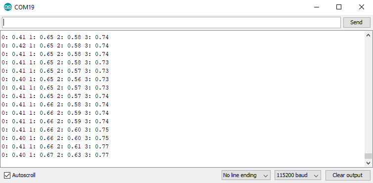
Uploading this sketch and opening the serial monitor will show a stream of calibrated values. Use these to scale
any other variable you’d like in your project.
Calibrated Hand Output - click the image for a closer look
Resources and Going Further
Now that you’ve successfully got your Qwiic Flex Glove Controller up and running, it’s time to incorporate it into
your own project!
For more information, check out the resources below:
Schematic (PDF)
Eagle Files (ZIP)
ADS1015 Datasheet (PDF)
Qwiic Landing Page
GitHub Repos
Product
Arduino Library
SparkFun Product Showcase: Qwiic Flex Glove Controller
Need even more inspiration for your next project? Check out some of these related tutorials:
AS726X NIR/VIS Spectral Sensor Hookup
Guide
It's now easier than ever to measure and characterize
how different materials absorb and reflect different
wavelengths of light. The AS726X spectral sensors
allow you to detect wavelengths in the visible range
(VIS) and near infrared range (NIR)!
Qwiic HAT for Raspberry Pi Hookup Guide
Get started interfacing your Qwiic enabled boards with
your Raspberry Pi. This Qwiic connects the I2C bus
(GND, 3.3V, SDA, and SCL) on your Raspberry Pi to
an array of Qwiic connectors.

Table of contents
Other sparkfun Controllers manuals


