ADSE 650 / USER MANUAL / Reference V15-D2-0174-0 / February 2023 3/79
Exhaustive Table of Content
Revision of the Manual
Contact
Safety Advisory
PRESENTATION
General
Applications
Characteristics
Units, Range and Precision
Domain Flight Option
Technical description
USER ACCESS
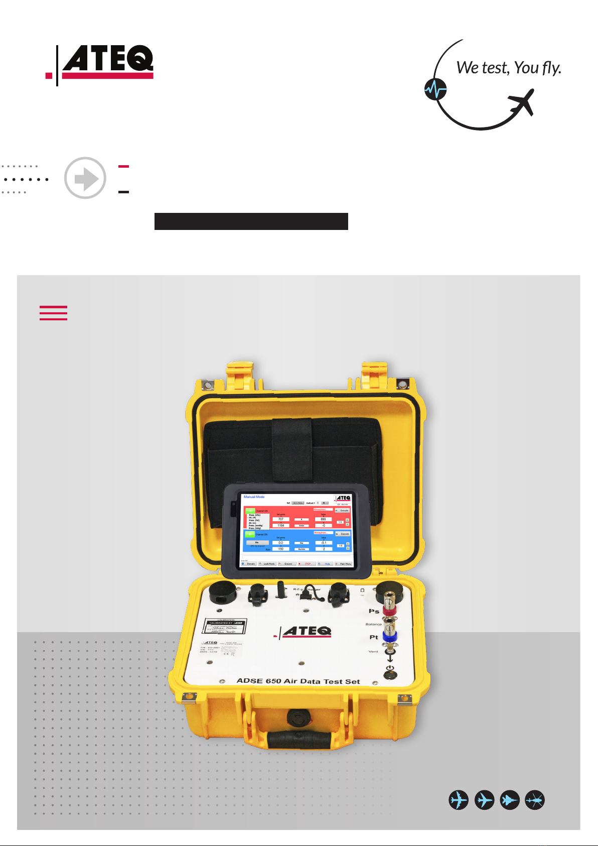
ADSE 650 RCU front panel
ADSE 650 EPU front panel
GETTING STARTED
Initial Procedures
OPERATOR INTERFACE
Starting software
Access to the ight domains
Measure/Manual Mode
Automatic program mode
File Manager
General Information
Help on line
Exiting the software
Keyboard conguration
Manual grounding
MAINTENANCE
Low Level Maintenance
Autotest Function
Maintenance Plan
Error and warning list
OPTIONS
1/ RCU link-serial Option
2/ EPR Option
3/ Cabin Pressure Option
4/ Outow Valve Option
SAFETY INFORMATION
EXHAUSTIVE TABLE OF CONTENT
.../...
Access to the ight domains............................................................................................ 20
Select a ight domain....................................................................................................... 20
Creating a ight domain ................................................................................................... 22
Editing, renaming and deleting a ight domain ................................................................. 23
Access to the Measure/Manual Mode............................................................................. 24
Changing the unit on th Ps and Pt channels ...................................................................... 25
Activating a channel......................................................................................................... 26
Generating on the Ps or Pt channel .................................................................................. 27
Outow indicators........................................................................................................... 28
Leak test .......................................................................................................................... 29
Return to the ground........................................................................................................ 30
Displaying the current ight domain ................................................................................ 31
Automatic program mode ............................................................................................... 32
Writing a new program .................................................................................................... 33
Editing, Renaming and deleting a program le.................................................................. 36
Executing a program ........................................................................................................ 37
Operating Mode......................................................................................................... 44
File format fo the data recorded by the semi-automatic program ............................... 45
File Manager.................................................................................................................... 46
General Information........................................................................................................ 47
Parameters ...................................................................................................................... 48
User settings............................................................................................................... 48
RS232 ......................................................................................................................... 48
Wi-Fi........................................................................................................................... 49
Ground ....................................................................................................................... 49
Reference ................................................................................................................... 50
Calibration .................................................................................................................. 50
Password ......................................................................................................................... 52
Enter a password ............................................................................................................. 54
Ground function .............................................................................................................. 55
Languages........................................................................................................................ 56
Help on line ..................................................................................................................... 57
Exiting the software........................................................................................................ 57
Keyboard conguration .................................................................................................. 58
Numerical keyboard......................................................................................................... 58
Alpha-Numeric Keyboard ................................................................................................ 58
Manual grounding ........................................................................................................... 59
MAINTENANCE 60
Low Level Maintenance................................................................................................... 60
Autotest Function ........................................................................................................... 60
Maintenance Plan............................................................................................................ 66
Error and warning list...................................................................................................... 67
OPTIONS 18
1/RCU link-serial Option................................................................................................. 69
2/EPR Option .................................................................................................................. 70
3/Cabin Pressure Option................................................................................................. 73
4/Outow Valve Option.................................................................................................. 75
SAFETY INFORMATION 77
Operating environment .................................................................................................. 77
Safety for lithium Polymer battery use ........................................................................... 77
Important instructions (for service personnel only) ....................................................... 78
Recycling ......................................................................................................................... 78