manuals.online logo
Brands
  1. Home
  2. •
  3. Brands
  4. •
  5. ATI Technologies
  6. •
  7. Amplifier
  8. •
  9. ATI Technologies ATP 7500 User manual

ATI Technologies ATP 7500 User manual

Other manuals for ATP 7500

1

Other ATI Technologies Amplifier manuals

ATI Technologies M1000 Operating instructions

ATI Technologies

ATI Technologies M1000 Operating instructions

ATI Technologies ATP 8500 User manual

ATI Technologies

ATI Technologies ATP 8500 User manual

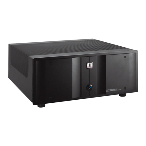
ATI Technologies ATP 7500 User manual

ATI Technologies

ATI Technologies ATP 7500 User manual

ATI Technologies SUM100 User manual

ATI Technologies

ATI Technologies SUM100 User manual

ATI Technologies DDA SERIES Operating instructions

ATI Technologies

ATI Technologies DDA SERIES Operating instructions

ATI Technologies PURE BALANCE AT2000 Series User manual

ATI Technologies

ATI Technologies PURE BALANCE AT2000 Series User manual

ATI Technologies ADA208PH Operating instructions

ATI Technologies

ATI Technologies ADA208PH Operating instructions

ATI Technologies P100S Operating instructions

ATI Technologies

ATI Technologies P100S Operating instructions

ATI Technologies AT7000 Series User manual

ATI Technologies

ATI Technologies AT7000 Series User manual

ATI Technologies HDA100 Operating instructions

ATI Technologies

ATI Technologies HDA100 Operating instructions

ATI Technologies AT1820 Series User manual

ATI Technologies

ATI Technologies AT1820 Series User manual

ATI Technologies AT2000 SERIES User manual

ATI Technologies

ATI Technologies AT2000 SERIES User manual

ATI Technologies L1000 Installation guide

ATI Technologies

ATI Technologies L1000 Installation guide

ATI Technologies M100 Operating instructions

ATI Technologies

ATI Technologies M100 Operating instructions

ATI Technologies BU400 Operating instructions

ATI Technologies

ATI Technologies BU400 Operating instructions

ATI Technologies P1000 Operating instructions

ATI Technologies

ATI Technologies P1000 Operating instructions

ATI Technologies ATP 8500 User manual

ATI Technologies

ATI Technologies ATP 8500 User manual

ATI Technologies AT6012 User manual

ATI Technologies

ATI Technologies AT6012 User manual

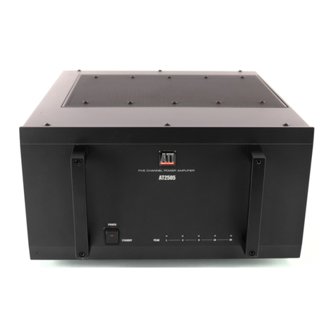
ATI Technologies AT2505 User manual

ATI Technologies

ATI Technologies AT2505 User manual

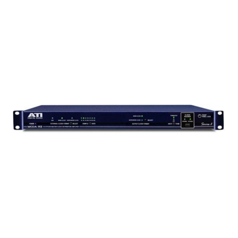
ATI Technologies MCDA-112 Operating instructions

ATI Technologies

ATI Technologies MCDA-112 Operating instructions

ATI Technologies DA1000 Operating instructions

ATI Technologies

ATI Technologies DA1000 Operating instructions

ATI Technologies DA208 Operating instructions

ATI Technologies

ATI Technologies DA208 Operating instructions

ATI Technologies HDA600 Operating instructions

ATI Technologies

ATI Technologies HDA600 Operating instructions

ATI Technologies AT6000 SIGNATURE SERIES User manual

ATI Technologies

ATI Technologies AT6000 SIGNATURE SERIES User manual

Popular Amplifier manuals by other brands

Magnat Audio EDITION FOUR Owner's manual/warranty document

Magnat Audio

Magnat Audio EDITION FOUR Owner's manual/warranty document

Inter-m PA-2000A Operation manual

Inter-m

Inter-m PA-2000A Operation manual

Yamaha TX6n owner's manual

Yamaha

Yamaha TX6n owner's manual

Peavey TNT 150 user guide

Peavey

Peavey TNT 150 user guide

Bosch LBB 1903/10 Installation and user instructions

Bosch

Bosch LBB 1903/10 Installation and user instructions

Avocent Emerge DA1200D Installer/user guide

Avocent

Avocent Emerge DA1200D Installer/user guide

Redgum RGi35 operating instructions

Redgum

Redgum RGi35 operating instructions

Cambridge Audio AXA25 user manual

Cambridge Audio

Cambridge Audio AXA25 user manual

Alpine MRP-M200 owner's manual

Alpine

Alpine MRP-M200 owner's manual

Technical Pro H1502UrBT user manual

Technical Pro

Technical Pro H1502UrBT user manual

FMS EMGZ307 operating manual

FMS

FMS EMGZ307 operating manual

Racal Instruments 5601 user manual

Racal Instruments

Racal Instruments 5601 user manual

Valcom V-1094A Technical specifications

Valcom

Valcom V-1094A Technical specifications

Cambridge Audio 851D user manual

Cambridge Audio

Cambridge Audio 851D user manual

QSC 3800 Specifications

QSC

QSC 3800 Specifications

NAD C300 owner's manual

NAD

NAD C300 owner's manual

Rotel RMB-1077 owner's manual

Rotel

Rotel RMB-1077 owner's manual

Peavey Monitor 300 Series operating guide

Peavey

Peavey Monitor 300 Series operating guide

manuals.online logo
manuals.online logoBrands
  • About & Mission
  • Contact us
  • Privacy Policy
  • Terms and Conditions

Copyright 2025 Manuals.Online. All Rights Reserved.

ATP7500
DIGITAL PREAMPLIFIER-PROCESSOR
OWNER’S GUIDE
TRANSLATING
TECHNOLOGY
Safety Instr ctions
WARNING: TO REDUCE THE RISK OF FIRE OR
ELECTRIC SHOCK, DO NOT EXPOSE THIS UNIT TO
RAIN OR MOISTURE.
Read all the safety and operating instructions before
connecting or using this unit.
All warnings on the unit and in this operating manual should
be adhered to.
All operating and use instructions should be followed.
Do not use this unit near water: for example, near a bathtub,
washbowl, kitchen sink, laundry tub, in a wet basement, or
near a swimming pool.
This unit should be installed so that its location or position
does not interfere with its proper ventilation. or example,
it should not be situated on a bed, sofa, rug, or similar surface
that may block the ventilation openings: or placed in a built-in
installation, such as bookcase or cabinet, that may impede
the flow of air through its ventilation openings.
The unit should be situated away from heat sources such as
radiators, heat registers, stoves, or other devices (including
amplifiers) that produce heat.
The unit should be connected to a power-supply outlet only of
the voltage and frequency marked on its rear panel.
The power-supply cord should be routed so that it is not likely
to be walked on or pinched, especially near the plug,
convenience receptacles, or where the cord exits from the unit.
Clean unit only as recommended in this instruction manual.
The power-supply cord of the unit should be unplugged from
the wall outlet when it’s to be unused for a long period of time.
Care should be taken so that objects do not fall, and liquids
are not spilled, into the enclosure through any openings.
The unit should be serviced by qualified service personnel when:
A. The power cord or the plug has been damaged; or
B. Objects have fallen, or liquid has been spilled, into the
unit; or
C. The unit has been exposed to rain, or liquids of any kind; or
D. The unit does not appear to operate normally, or exhibits a
marked change in performance; or
E. The device has been dropped, or the enclosure damaged.
To prevent electric shock, do not use the polarized plug with
an extension cord, receptacle or other outlet unless the
blades can be fully inserted to prevent blade exposure.
Page 2
Please Read First
CAUTION: To reduce the risk of electrical shock, do not
remove the cover (or back). No user serviceable parts inside.
Refer servicing to qualified service personnel.
WARNING: To reduce the risk of fire or electric shock, do
not expose this appliance to rain or moisture.
The lightning flash with arrowhead, within an
equilateral triangle, is intended to alert the
user to the presence of uninsulated “dangerous
voltage” within the product’s enclosure that
may be of sufficient magnitude to constitute a
risk of electrical shock to persons.
The exclamation point within an equilateral
triangle is intended to alert the user to the
presence of important operation maintenance
(servicing) instructions in the literature
7accompanying the appliance.
PRECAUTIONS:
Certain precautions must be taken in order to ensure proper
operation of your preamplifier-processor.
1. Never expose the unit to moisture
2. Never plug an input cable into the preamplifier while the
preamplifier is turned on.
3. Never apply the “thumb test” (touching the “hot” lead of
the input cable with your finger) to the tip of the input
cable or input jack of the preamplifier. R rectification
and/or hum may be created and could cause damage to the
loudspeakers. ATI will not be responsible for damage to
the loudspeakers, amplifiers or other related equipment
due to improper use of the equipment.
4. Avoid restricting the airflow around the unit. Good
airflow is necessary to help insure proper operation.
5. Do not stack other system components or any other
materials directly on top of the unit. The heat dissipating
system of the preamplifier depends on free flowing air
around the chassis.
Table of Contents
Please Read irst ............................................................ Page 2
Safety Instructions ........................................................ Page 2
Table of Contents .......................................................... Page 3
Introduction ................................................................... Page 3
Product Warranty Registration.................................... Page 3
eatures........................................................................... Page 3
Unpacking ....................................................................... Page 3
General Recommendations .......................................... Page 4
Precautions..................................................................... Page 4
ront Panel Controls ..................................................... Page 4
System Setup .......................................................Page 5, 6 & 7
Rear Panel Connections................................................ Page 7
Typical Source Connections ......................................... Page 8
5.1 Speaker Setup & Configuration ............................ Page 9
6.1 Speaker Setup & Configuration ........................... Page 10
7.1 Speaker Setup & Configuration ........................... Page 11
Remote Control Operation ................................ Page 12 & 13
Remote Control Programming .................................. Page 14
Volume Punch Through .............................................. Page 15
Programming the Macros ........................................... Page 15
Programming a Macro Sequence .............................. Page 15
Replacing the AC Power use ..................................... Page 16
Care and Maintenance ................................................ Page 16
Trouble Shooting ......................................................... Page 16
ATI Service Information ............................................. Page 16
Specifications ............................................................... Page 17
Warranty Terms and Conditions ............................... Page 18
Congrat lations
Thank you for purchasing the ATI ATP7500 Digital
Preamplifier-Processor . This product is a fully integrated,
high resolution audio/video control center. The ATP7500
incorporates the most exacting and accurate surround
technology available in its class for home theater. The
ATP7500 represents a unique synthesis of form, function
and fidelity all superbly crafted to deliver all the critical
requirements of a truly high performance home theater
system. Please read this manual thoroughly and carefully
follow all instructions to ensure maximum utility and
enjoyment from your investment. This important information
will help you make certain that the preamplifier-processor is
properly configured for operation with the rest of the
equipment in your system.
If you have any questions about this product, its installation
or operation, please contact us via e-mail at
[email protected] or via telephone at 888-777-8507.
Prod ct Warranty Registration
Be sure to complete and return your Product Warranty
Registration Card immediately. This will entitle you to
warranty coverage as outlined in the section “WARRANTY”
at the end of this manual.
ATP7500 Feat res
Surround Modes include Dolby Digital 5.1®, Dolby Digital
Surround EX®, Dolby Surround Pro Logic II®, DTS Digital
Surround 5.1®, DTS-ES Surround 6.1®, DTS Neo:6®and
71. Matrix Music Mode®.
Full Function Remote Control is illuminated and can be
programmed to operate several other components.
RS232 Port is bi-directional for custom integration and
system automation.
9 Analog Inputs include 7.1-channel analog pass-through.
Video Switching includes composite video, S-video, and
component video and can be accessed by 7 inputs .
2nd Zone for independent audio and video.
rigger Outputs to control other source devices.
Crystal D/A and A/D converters.
AM/FM uner with preset memory.
S-Video to Component Video Conversion lets you send all
video
sources to the TV through one component video output.
Standby Power Mode for improved reliability.
Unpacking
Your new product was diligently handcrafted, thoroughly
tested and carefully packed at our factory in California, USA.
Please remove the ATP7500 carefully from the box.
The following accessories should be included inside the box:
AC Power Cord
Remote Control with Batteries
Warranty Registration Card
In the unlikely event that the ATP7500 was damaged in
shipment, be sure to save the carton and all packing material
as evidence for the freight carrier’s inspection.
Should
you
discover that your preamplifier has been damaged
during
shipping, please contact your dealer or ATI immediately
and
request the name of the carrier so a written claim may be made.
THE RIGHT TO A CLAIM AGAINST A PUBLIC CARRIER CAN BE
OR EITED I THE CARRIER IS NOT NOTI IED PROMPTLY IN
WRITING AND I THE SHIPPING CARTON AND PACKING
MATERIALS ARE NOT AVAILABLE OR INSPECTION BY THE
CARRIER. SAVE ALL PACKING MATERIALS UNTIL THE CLAIM
IS SETTLED.
CAU ION: NEVER SHIP HIS PRODUC WI HOU
HE ORIGINAL BOX AND PACKING. Page 3
Page 4
General Recommendations
Before you begin the SETUP, we strongly recommend that you
take a few moments to:
• amiliarize yourself with the controls and functions of the
preamplifier-processor.
• Carefully study the system connection diagrams and basic
operational instructions.
• ully understand the setup and programming instructions.
Preca tions
• Install the ATP7500 on a solid shelf.
• Be sure that the area surrounding the unit is well
ventilated and not near a heat source of any kind.
• Prevent any moisture from entering the unit.
• Do not place anything on top of the unit.
• Make all connections BE ORE you turn the unit on.
Front Panel Controls
A Po er S itch
Switches the unit into standby mode and the LED turns on.
Do not use this switch to turn the unit off; use the O button.
PLEASE NOTE: TO TURN THE UNIT ON, YOU MUST
SELECT A SOURCE EITHER ON THE FRONT PANEL
OR THE REMOTE CONTROL.
B Source Buttons
When a source button is pressed, that source is selected
and the unit is turned on from the STANDBY mode.
C Seek Up
Advances the tuner to the next higher valid station.
D Volume Up
Raises the volume in 1dB increments. The volume will
increase faster if the button is held down.
E7.1
Selects multi-channel audio and DVD Video.
F AM/FM
Selects AM or M reception.
G Seek Do n
Advances the tuner to the next lower valid station.
H Volume Do n
Lowers the volume in 1dB increments. The volume will
decrease faster if the button is held down.
I Zone 2
Toggles the CD, TAPE, TUNER, AUX source buttons, AM/ M,
VOLUME, MUTE, SEEK, and O to control ZONE2. If no
settings are selected,the display will default to MAIN ZONE.
J Mute
Toggles the muting for MAIN ZONE and ZONE2.
KOff
Turns the system from ON to Standby.
KJIHGFE
B CA D
System Set p
We urge you, at least the first time you set up your system, to
take the time and thoroughly follow each of the following
steps precisely. Even though this may take some time, it will
guarantee that your system will function properly and offer
the most rewarding results. If you “do it right” the first time,
future changes will be easier to implement.
Press the “MENU” button on the remote and the On Screen
Display (OSD) will appear as in the example below:
Using the Remote’s keypad, press the button corresponding to
what you want to setup. Selected function will be highlighted.
1. Speaker Size
Speaker size refers to your speaker’s actual frequency
response. or each channel, selecting “large” means that the
channel will be set to “full range” by the processor. Selecting
“small” means that the processor will filter out the low bass
from this channel and redirect this part of the signal to the
subwoofer. or some channels you may select “none” if you
don’t use a speaker for that channel.
2. Speaker Distance
You will need to set the distance, in feet, between your
listening position and each speaker. These settings automatically
calculate the accurate delay settings for each channel. Select
the number of the channel you wish to set, then press the
SELECT button to increase the distance. This setting is in
increments of 1 foot up to 30 feet, then start over at 1 foot.
3. Input Assignment
The default input assignment settings will be shown on the
screen. You can leave them as is or you may reassign any of
the 6 digital inputs. Select the number corresponding to the
input you wish to change then press the SELECT button. Each
time you press the SELECT button, the selected input will
scroll through each available digital input and then return to
the analog input. You may associate each analog input to any
digital input. Keep in mind that each analog input is labeled
on the back of the unit by its name, unlike the digital inputs
which are numbered 1 through 6.
Page 5
1. Quick Setup – Speaker size
2. Quick Setup – Speaker distance
3. Input assignment
4. Tuner / PAL / NTSC Settings
5. Bass trim
6. Calibration
7. Compression
8. Status Display
9. DVD Audio Full Range
0. Reset to Defaults
Exit
FIGURE 1: MAIN MENU
1. Front speakers
– Toggle to small or large
2. Center speaker
– Toggle to small, large or none
3. Surround speakers
– Toggle to small or large
4. Rear speakers
– Toggle to small, large or none
5. Subwoofer
– Toggle to yes or no
Exit – Return to main menu
FIGURE 2: SPEAKER SIZE MENU
1. VCR1
2. VCR2
3. TV
4. LD
5. AUX
6. SAT
7. DVD
8. CD
9. TAPE
Exit – Return to main menu
FIGURE 4: INPU ASSIGNMEN MENU
1. Set left front speaker distance
2. Set center speaker distance
3. Set right front speaker distance
4. Set right surround speaker distance
5. Set right back speaker distance
6. Set left back speaker distance
7. Set left surround speaker distance
Exit – Return to main menu
FIGURE 3: SPEAKER DIS ANCE MENU
Advanced Input Assignment: Analog Input Name Change
This set is available should you wish to rename any of the
analog inputs. Press the number of the input you wish to
rename then press the GUIDE button. A new menu on the
OSD page will appear. This menu will show the default and
actual name as well as five Xs. Use the cursor buttons to move
up, down, left or right to select and change letters and/or
numbers to create the new name. Press EXIT when done to
return to the previous menu.
4. uner and PAL/N SC Settings
These settings are for the M tuner OS video setting. Press
the number corresponding to your location for the tuner
setting. An “X” following the region indicates the current
setting. The “TV Setting” must be made according to your
location. NTSC for North America and PAL for most of Europe.
5. Bass rim
You may adjust the bass level for each input independently.
Press the number representing the input you wish to change,
then press VOLUME UP or VOLUME DOWN to adjust the bass
in 1dB increments.
6. Calibration
You must calibrate the relative level of each channel to get a
proper surround sound presentation. or the most precise
calibration, you should use a sound pressure level (SPL)
meter. A loud pink noise tone will come from the selected
speaker when you press the associated button. Adjust each
channel’s output level to 75dB using the VOLUME UP or
VOLUME DOWN buttons. The levels should be adjusted from
the same listening position used in STEP2.
7. Compression
This feature allows you to compress the dynamic range of the
sound which may be helpful for low volume listening late at
night. Turning this feature off will permit full dynamic range.
When turned on, louder passages are softened and softer
passages are increased to maximize intelligibility of speech.
Use the SELECT button to toggle between on and off.
8. Status Display
Press the SELECT button to toggle between STATUS DISPLAY
ON and O . When turned on, an OSD appears for 2 seconds
each time you press a button. This OSD appears only when
using the “main out” composite or S-Video outputs. The
selected INPUT<SURROUND MODE and VOLUME LEVEL will
be displayed.
9. DVD Audio Full Range
This setting applies only to the 7.1 “analog pass through” input.
Use the SELECT button to toggle between “yes” and “no”.
When “yes” is selected, all signals present at the input will be
sent to the output and be affected ONLY by the VOLUME
control. When “no” is selected, the filters are defined by the
“SPEAKER SIZE” settings chosen in Step1. Channels set to
“large” will receive a full bandwidth signal while channels set
to “small” will have limited low frequency response (80Hz
filter). The analog filters will remove the low bass frequencies
from the signal and redirect it to the subwoofer.
Page 6
1. USA
2. South American
3. Europe
4. Japan
5. Far East
6. South African
7. TV Setting
Exit – Return to main menu
FIGURE 5: UNER AND PAL/N SC SE INGS MENU
1. VCR1
2. VCR2
3. TV
4. LD
5. AUX
6. SAT
7. DVD
8. CD
9. TAPE
Exit – Return to main menu
FIGURE 6: BASS RIM MENU
1. Set left front speaker level
2. Set center speaker level
3. Set right front speaker level
4. Set right
surround speaker
level
5. Set right back speaker level
6. Set left back speaker level
7. Set left surround speaker level
8. Set subwoofer speaker level
Exit – Return to main menu
FIGURE 7: CALIBRA ION MENU
Page 7
0. Reset to Defaults
We recommend not using this feature unless there is trouble
with any of the settings you have made. This is a quick way to
return the unit to “out of box” conditions. This will also be
used when there are updates to the firmware. Press “0” on
the remote when in the main menu. You can toggle between
“NO” and “YES” by using the SELECT button. Please exercise
extreme caution.
CAU ION: USE EX REME CAU ION WHEN USING HIS
FEA URE AS I COULD RE URN ALL YOUR SE INGS O
FAC ORY DEFAUL S.
Rear Panel Connections
Audio and Video Signal Connections
The rear panel is divided into different sections whereby the
connectors are grouped together in a logical manner. Digital
inputs are grouped together and are labeled “DIG1” through
“DIG6”. Each of these six digital inputs are assignable to any
of the nine labeled source inputs as previously discussed.
Most of the analog inputs with the exception of “CD”, “TAPE”,
and “7.1 Audio” are grouped together where they are associated
with a video input, each forming a vertical line of connectors.
or each of these labeled inputs, you can plug in one video
input, allowing for a choice of the type of connection: either a
choice of Composite Video and S-Video or Component Video
and S-Video. The “7.1 Audio Input” is a special multi-channel
analog pass-through that can be used for a DVD-Audio or
SACD player.
The outputs are grouped into “MAIN OUT” and “RECORD
OUT” sections. The “MAIN OUT” section has an eight channel
(7.1) preamplifier output and 4 video outputs; two are
Composite Video and one is S-Video and one is Component
Video. ONLY the Composite and S-Video outputs carry the
OSD signal. To correctly setup your ATP7500 using the
previously discussed OSD menus, make sure to connect your
screen to at least one of the Composite or S-Video outputs
and remember to select this input on your screen whenever
you need to access the OSD of the ATP7500.
The “RECORD OUT” section has two audio/video outputs that
you can use to connect to a VCR or a tape deck, for example.
The audio outputs are fixed line level; they are not affected
by the processor’s volume control setting. The video outputs
are Composite Video and S-Video for each of the two “RECORD
OUT” connections. These video outputs provide NO OSD
information. There is also a digital output available on an
optical TOSLINK connector located near the “DIGITAL INPUTS”.
It may be used to connect to a CD-R recorder for example.
The “2nd Zone” section has one fixed output, one variable
output and one second zone dedicated input that is accessible
only from the “2nd Zone”. The “2nd Zone” has limited access
to which input source may be selected; the dedicated “2nd
Zone” input, CD, TAPE, or the AM/ M Tuner.
Control Signal Connections
The input labeled “IR INPUT” (infrared remote control) is
designed to receive an electrical signal corresponding to the
infrared signal of a remote device such as a repeater that may
be installed in the “2nd Zone”.
The RS232 port allows the control of the ATP7500 from a
distant programmed controller (such as a Crestron®system).
Information about the RS232 codes can be obtained from
ATI on request. The RS232 port can also be used to download
software revisions for future upgrades.
There are three trigger outputs that can be used to control
other components. Two are associated with the main zone
and one with the “2nd Zone”. Each of them activates when
their respective zone is turned on. The output labeled “12V
Trigger” is rated at 200mA. The outputs labeled “2nd Zone
Trigger” and “Main Zone” are dry contacts rated at 1A each.
All triggers operate with a 5 second delay.
Page 8
Typical So rce Connections
Here is a typical source connection for the ATP7500. It is
shown only as an example and is by no means mandatory.
There are endless possibilities regarding what and how you
can connect to the rear panel.
FM Antenna (not included)
DVD Player DSS Satellite Receiver
VCR
Page 9
5.1 Speaker Set p & Config ration
Po ered
Sub
Woofer
Listening Room
Five
Channel
Po er
Amplifier
ATP7500
Rear
Panel
Page 10
6.1 Speaker Set p & Config ration
Po ered
Sub
Woofer
Listening Room
Six
Channel
Po er
Amplifier
ATP7500
Rear
Panel