Atim Cloud Wireless ACW/LW8-THAQ User manual

ATIM Radiocommunications
Chemin des Guillets
38250 Villard de Lans
France
www.atim.com
Atim Cloud Wireless®
Temperature, humidity and
air quality (CO2, VOC)
User Guide
Concerned models:
ACW/LW8-THAQ
ACW/SF8-THAQ

2
ATIM_ACW-THAQ_UG_EN_V1.7
Table of contents
THIS USER GUIDE DEALS WITH THE FOLLOWING REFERENCES...................................................................................................... 4
DOCUMENT VERSION HISTORY .................................................................................................................................................. 4
DISCLAIMER ................................................................................................................................................................................ 5
TRADEMARKS AND COPYRIGHT ................................................................................................................................................... 5
DECLARATION OF COMPLIANCE................................................................................................................................................... 5
ENVIRONMENTAL RECOMMENDATIONS...................................................................................................................................... 6
A.EXPLOSIVE ATMOSPHERE .............................................................................................................................................................. 6
B.ENVIRONMENT ........................................................................................................................................................................... 6
C.RADIO ...................................................................................................................................................................................... 7
TECHNICAL FEATURES................................................................................................................................................................. 8
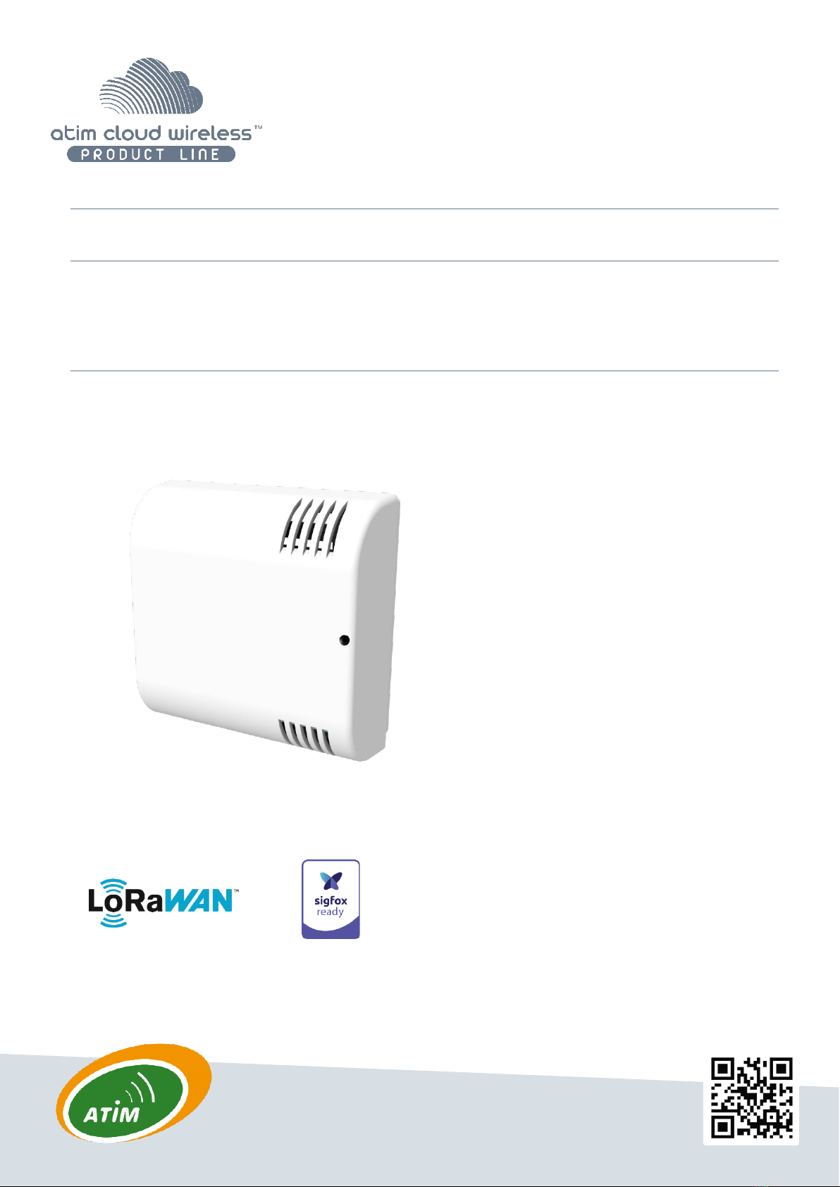
A.PRODUCT .................................................................................................................................................................................. 8
B.SENSORS FUNCTIONS ................................................................................................................................................................... 8
CASING..................................................................................................................................................................................... 10
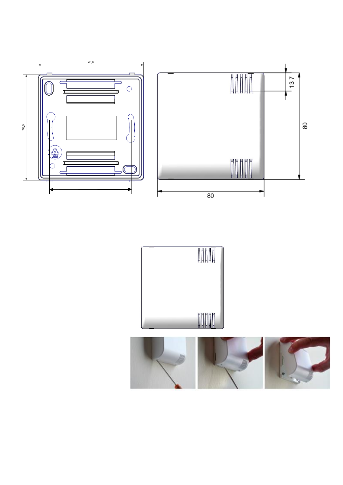
A.SPACE REQUIREMENTS ............................................................................................................................................................... 10
B.MOUNTS TO ............................................................................................................................................................................ 10
C.INSTALLATION .......................................................................................................................................................................... 11
D.IDENTIFICATION........................................................................................................................................................................ 11
OPERATION .............................................................................................................................................................................. 12
A.MODE OF OPERATION ................................................................................................................................................................ 12
B.PUTTING THE PRODUCT INTO SERVICE............................................................................................................................................ 13
C.SENDING A TEST FRAME.............................................................................................................................................................. 14
D.DEEP SLEEP.............................................................................................................................................................................. 14
E.RADIO MODULE ACTIVITY ............................................................................................................................................................ 14
F.THRESHOLD EXCEEDED ............................................................................................................................................................... 14
G.SUBSTITUTION TO THE MAGNET ................................................................................................................................................... 15
H.BATTERY PASSIVATION................................................................................................................................................................ 15
I.AIR QUALITY INDICATION............................................................................................................................................................ 15
J.NIGHT MODE ........................................................................................................................................................................... 16
ACW CONFIGURATOR............................................................................................................................................................... 17
A.COMPATIBLE CONFIGURATOR VERSION.......................................................................................................................................... 17
B.ACW-THAQ SETUP.................................................................................................................................................................. 18
Emission and sampling period of the frame ........................................................................................................................... 18
Keep alive frame period .......................................................................................................................................................... 19
Frame timestamp .................................................................................................................................................................... 19
Configuration of the Radio module......................................................................................................................................... 19
Product clock............................................................................................................................................................................ 20
Product versions ...................................................................................................................................................................... 20
Configuration of sensors ......................................................................................................................................................... 21
Temperature and humidity .......................................................................................................................................................................21
Air quality (VOC and CO2)..........................................................................................................................................................................22
CO2Calibration..........................................................................................................................................................................................23
..................................................................................................................................................................................................................23
Advanced configuration............................................................................................................................................................................23
Configuration validation............................................................................................................................................................................24
C.FACTORY SETTINGS.................................................................................................................................................................... 25
D.UPDATE OF ACW ..................................................................................................................................................................... 26
UPLINK FRAMES FORMAT ........................................................................................................................................................ 27

3
ATIM_ACW-THAQ_UG_EN_V1.7
A.SIGFOX AND LORAWAN............................................................................................................................................................ 27
Classic frame............................................................................................................................................................................ 27
Different frames’ type ............................................................................................................................................................. 28
Measurement’s frame ............................................................................................................................................................. 28
Alert measurement frame ....................................................................................................................................................... 30
Keep alive frame...................................................................................................................................................................... 31
Error and alarm generic frame................................................................................................................................................ 32
B.EXAMPLES OF FRAMES ............................................................................................................................................................... 34
Measurement frame................................................................................................................................................................ 34
Alert measurement frame ....................................................................................................................................................... 35
DOWNLINK ............................................................................................................................................................................... 36
A.CONFIGURATION OF THE FRAME PARAMETERS (SENDING PERIOD,NUMBER OF SAMPLES,ETC.).................................................................. 36
B.ACTIVATION OF THE SENSORS ...................................................................................................................................................... 37
THRESHOLD CONFIGURATION ...................................................................................................................................................... 38
C. ................................................................................................................................................................................................... 38
D.CONFIGURATION OF THE TEMPERATURE COMPENSATION .................................................................................................................. 38
Offset ....................................................................................................................................................................................... 38
Coefficient ................................................................................................................................................................................ 39
E.ALTITUDE CONFIGURATION (COMPENSATION OF THE CO2SENSOR)..................................................................................................... 39
F.AIR QUALITY INDEX CONFIGURATION............................................................................................................................................. 39
G.LED INDICATOR THRESHOLD CONFIGURATION ................................................................................................................................ 40
H.NIGHT MODE CONFIGURATION .................................................................................................................................................... 40
I.RESERVED CODES FOR FUTURES SOFTWARE EVOLUTIONS................................................................................................................... 41
TECHNICAL SUPPORT................................................................................................................................................................. 42

4
ATIM_ACW-THAQ_UG_EN_V1.7
This user guide deals with the following references
Document version history
Version
Date
Description
Author
Concerned
software
version
0.1
23/11/2020
Document creation
AC
V0.0.1
0.2
10/12/2020
Correction of the datalogging downlink frame
description
AC
V0.0.1
1.0
15/02/2021
Air Quality addition (sensor, config, frames) +
description of downlink frames for
temperature compensation
AC
V0.0.2
1.1
29/03/2021
CO2 addition
AC
V0.0.2
1.2
12/05/2021
Add Downlink frame for the configuration of
CO2 sensor + update configuration chapter +
guidance for air quality indicator
AC
V0.0.3
1.3
22/06/2021
Compatibility mode regarding repeaters
LoRa/LoRaWAN and FSK/Sigfox description
Modification of the operation mode
description: LED behavior when searching for a
network.
Add guidance notes for samples sorting in
periodic frame
AC
V0.0.4
1.4
28/09/2021
Add information about new product features
Detail configuration of new settings
AC
V1.0.0
1.5
10/03/2022
Various corrections
FR
V1.0.0
1.6
15/03/2022
Corrections
MD
V1.0.0
1.7
23/05/2022
Add info about CO2 calibration
YLB
V1.0.6
Product references
Product Version (on the
product label)
LoRaWAN
ACW/LW8-THAQ
A.8
Sigfox
ACW/SF8-THAQ
A.8

5
ATIM_ACW-THAQ_UG_EN_V1.7
Disclaimer
The information contained in this document is subject to change without warning and does not represent a
commitment on the part of ATIM radiocommunications. ATIM radiocommunications provides this document ‘as-is’
with no warranty of any kind, express or implied, including but not limited to implied warranties of merchantability or
fitness for a particular purpose. ATIM radiocommunications may make changes and/or improvements to this manual
or to the product(s) or program(s) described in this manual, at any time.
Trademarks and copyright
ATIM radiocommunications®, ACW ATIM Cloud Wireless® and ARM Advanced Radio Modem® are registered
trademarks of ATIM SARL in France. The other trademarks mentioned in this document are the property of their
respective owners.
Declaration of compliance
All ACW Atim Cloud Wireless® products comply with the regulatory requirements of the R&TTE Directive (1999/5/EC),
article 3:
1 SAFETY (Article 3.1a of the 1999/5/EC Directive)
NF EN60950-1 Ed. 2006/A1:2010/A11:2009/A12:2011 (health)
EN62479: 2010 (power <20mW) or EN62311:2008 (power > 20mW)
2 Electromagnetic compatibility (Article 3.1b of the 1999/5/EC Directive)
EN 301489-3 v1.4.1, EN 301489-1 V1.9.2
3 Efficient use of the radio frequency spectrum (Art.3.2 of the 1999/5/EC Directive)
ETSI EN300 220-2 v2.4.1 and EN300 220-1 v2.4.1

6
ATIM_ACW-THAQ_UG_EN_V1.7
Environmental recommendations
a. Explosive atmosphere
Except for the ACW-ATEX line specifically intended for this purpose, do not use ACW radio modems in the presence of
flammable gases or fumes. Using the equipment in such an environment constitutes a safety hazard.
b. Environment
Respect the temperature ranges for storage and operation of all products. Failing to respect these guidelines could
disrupt device operation or damage the equipment. ACW products in IP65 water- and dust-resistant housings may be
placed outdoors but must not be submerged under any circumstances.
Follow the instructions and warnings provided below to ensure your own safety and that of the environment and to
protect your device from any potential damage.

7
ATIM_ACW-THAQ_UG_EN_V1.7
General hazard –Failure to follow the instructions presents a risk of equipment damage.
Electrical hazard –Failure to follow the instructions presents a risk of electrocution and
physical injury.
Direct-current symbol
WARNING: do not install this equipment near any source of heat or any source of humidity.
WARNING: for your safety, it is essential that this equipment be switched off and disconnected from
mains power before carrying out any technical operation on it.
WARNING: the safe operation of this product is ensured only when it is operated in accordance with
its intended use. Maintenance may only be performed by qualified personnel.
Waste disposal by users in private households within the European Union. This symbol appears on a
product or its packaging to indicate that the product may not be discarded with another household
waste. Rather, it is your responsibility to dispose of this product by bringing it to a designated
collection point for the recycling of electrical and electronic devices. Collection and recycling waste
separately at the time you dispose of it helps to conserve natural resources and ensure a recycling
process that respects human health and the environment. For more information on the recycling
centre closest to your home, contact your closest local government office, your local waste
management service, or the business from which you purchased the product.
c. Radio
Modems in the ACW line are radio-communication modems that use the ISM (industrial, scientific, andmedical) bands,
which may be used freely (at no cost and with no authorization required) for industrial, scientific, and medical
applications.

8
ATIM_ACW-THAQ_UG_EN_V1.7
Technical features
a. Product
Dimensions
80 x 80 x 35 mm
Antenna
Integrated (¼ d’of wave)
Temperature
-40°C to +125°C (operation)
-40°C to+150°C (storage)
Mounts to
Wall
Casing
Indoor
Power supply
1 battery-pack [7,2 Ah]
Weight
200 g
Frequency
863 –870 MHz
Power
25 mW (14 dBm)
Rate
Sigfox : 100 bits/s
LoRaWAN : 300 bit/s to 10 Kbit/s
Consumption
Sigfox
LoRaWAN
Tx mode
60 mA
55 mA
Standby mode
60 µA
60 µA
Rx mode
50 mA
25 mA
b. Sensors functions
Temperature
Range
-40°C to +125 °C
Resolution
0,01°C
Precision between -40°C et +80°C
+/- 0.2°C
Humidity
Range
0 to 100 %RH
Resolution
0,01 %RH
Precision between 0 %RHC and 100 %RH (operation range)
+/- 2 %RH

9
ATIM_ACW-THAQ_UG_EN_V1.7
IMPORTANT NOTE
The VOC index represents the overall concentration of all VOCs (volatile organic compounds) and not a specific concentration
of a given compound. The index is defined on a scale from 0 to 500 (0 for almost zero VOC concentration and 500 for very high
VOC concentration).
The scale (unitless) below provides an approximate representation based on colours:
CO2
Range
0 to 40.000 ppm
Resolution
1 ppm
Precision between 400 ppm and 5000 ppm
± 40 ppm (+ 5 % of the measurement)
IMPORTANT NOTE
The CO2 measurement represents the concentration of carbon dioxide in the ambient air. In general, the measurement will
rarely drop below 400 ppm, this value being the minimum detection threshold in the outside air.
Here is an informative table providing air quality zones according to CO2 concentration:
VOC Index
Plage
0 to 500
Resolution
1
CRITICAL
EXCELLENT
GOOD
BAD
AVERAGE
400 ppm 600 ppm 800 ppm 1200 ppm 2000 ppm 5000 ppm
Outdoor air
Recommended in
establishments open
to the public*
Renew hte air
in the room
2000 ppm or +, the CO2
level is high and can cause
disturbances to the
occupants of the room
*According to the French health
protocol in school spaces

10
ATIM_ACW-THAQ_UG_EN_V1.7
Casing
a. Space requirements
b. Mounts to
ACW-THI modems are attached to a wall with two screws that fit into the two mounting holes on the back of the box.
The vents on the cover must be on
the right, in the same direction as
the photo opposite.
Match the pivots at the top of the
case base with their respective
locations on the back face.
To remove the two faces, place a
screwdriver in one of the two fixing
areas at the bottom * of the front
face and press inwards until the
cover is released from the base.
* It is imperative to open the case from below; opening from the top can
damage the circuit.
60
<- Mounting
holes ->
fixations

11
ATIM_ACW-THAQ_UG_EN_V1.7
c. Installation
For optimal results, it is recommended to install the box without environmental obstruction and to place it at a height
of approximately 1m50. For information, the antenna is integrated in the box. It must be mounted on a vertical
support, or fixed to a wall.
d. Identification
The product identifier is visible on the outside label on the back of the product, inside on the electronic card and in
the status bar of the configuration software.
For LoRaWAN modems, the communication keys are automatically given by the network (pairing by “Over The Air
Activation”, or OTAA).
Product serial N°
Product reference
Product revision N°
(hardware and firmware
technical state)
Datamatrix: Sigfox ID
or
LoRaWAN DevEUI
Sigfox ID or
LoRaWAN DevEUI
THAQ
ACW-THAQ label

12
ATIM_ACW-THAQ_UG_EN_V1.7
Operation
a. Mode of operation
The new generation 2020 ACW (Atim Cloud Wireless®) products are all based on the same internal software
(Firmware) and bring interesting new features such as the selection and visualization of their operating mode. To know
the status of the product, you just must pass a magnet briefly (<2 sec) against the QRCODE label or on the Pepper
boxes against the small diamond, which causes the LED indicator of the corresponding color to light up:
→→→→
Deep sleep mode: When you take the product out of its packaging, it is by default in this deep sleep mode, which
optimizes the life of the batteries by avoiding their oxidation. The product does not transmit and waits patiently
for you to wake it up.
Network pairing mode: This mode is active as soon as the product leaves the deep sleep mode and allows the
pairing to a network (automatic in case of battery change).
Configuration mode: this mode is active 5 minutes after the exit of the deep sleep mode and authorizes the
configuration of the product in Bluetooth thanks to the PC configurator or to the mobile application ATIM. During
these 5 minutes messages are sent by radio every minute (5 "radio frames"), that allows you to check that the product
works well, for example after having placed it under a cast iron manhole. After this period, the product goes into
operation mode and the Bluetooth is deactivated (possibility to reactivate it via Downlink).
Operating mode: this is the default mode after the product start-up phase. In this mode, the module periodically
sends measurements according to the configuration applied (if the product has never been configured, the
factory configuration applies, see Factory Configuration).
Internal fault mode: This mode allows the normal operation of the module to be interrupted when a critical
event occurs. The nature of the event can be multiple:
•Battery empty (Battery voltage < 2.2V)
•Internal error of the radio module
•System error
The entry in this mode "Internal fault" is signaled by a RED flashing of the LED of the product
If the error does not come from the radio module, the product will send 3 radio frames every 24 hours containing the
error code(s) (see chapter Frame Format for error codes). In addition, the product will emit a warning light depending
on the nature of the event.
Once in this mode, the module must be restarted (by disconnecting and then reconnecting the battery, by Downlink
command or with the magnet) to regain normal operation.

13
ATIM_ACW-THAQ_UG_EN_V1.7
b. Putting the product into service
Unless otherwise requested, ACW products are delivered with batteries connected and set to "deep sleep"
mode.
To place the product in its operating mode, hold a magnet against the QRCODE label for 6 seconds. During these six
seconds, the product's LED should blink WHITE and then GREEN at the end of the six seconds to indicate that the
product has been successfully switched on.
The ACW then enters the network pairing phase. During this phase, a FUSCHIA light signal with a fade effect
indicates that the search phase is in progress.
If the connection is successful, the product will emit a light signal indicating the quality of the network:
GREEN light signal: good network quality
•YELLOW light: average network quality
•ORANGE light: low network quality
•WHITE light: no information on network quality
The module will then enter its operating mode and start sending information to the network according to the
configuration.
NOTE
The LoRaWAN version, if it fails to connect, will go into simple sleep mode and make the next pairing attempt the next day and
every day until it successfully joins the network.
Special case
For a Sigfox product
•To have the information on the quality of the Sigfox network (GREEN, YELLOW or ORANGE light signal), it is
necessary to provide a Sigfox Downlink. It is this one which will allow to rule on the quality of the network.
The product emits at startup a test Uplink described in the chapter Classic frame (frame type 0x02). If a Sigfox
Downlink is provided, the information on the network quality will be sent back by the ACW (light signal). If no
Downlink is provided, the ACW will always display the WHITE light signal at the end.
•If a WHITE light signal is emitted by the product at the end of the 5min pairing phase and a Downlink has been
provisioned, it means that the Network is not accessible.
•If a WHITE light at the end of the 5min pairing phase is emitted by the product without a downlink having been
provisioned, this has no meaning as to the quality of the network. The network quality can be good or bad (or
non-existent).

14
ATIM_ACW-THAQ_UG_EN_V1.7
For a LoRaWAN product
•In the default LoRAWAN Class A operating mode, (see Radio settings chapter), if at the end of the 5 minutes
pairing phase, no network has been reached, then the product goes into standby and will restart a 5-minute
pairing phase 24 hours later. So, if the product is placed in an area not yet covered by a network, the product
will join it when connectivity is possible. There is no need to intervene on the product for it to join the
network.
•In the LoRa/LoRAWAN Repeater Compatibility operating mode, (see chapter Radio parameters), if at the end
of the 5 minutes of the pairing phase, no network has been reached, then the product emits a WHITE light
signal and enters its nominal operating mode. Even if no network has been reached, it is assumed with this
mode that an ATIM LoRa/LoRAWAN repeater located nearby will be able to repeat the Local frames emitted
by the product in LoRAWAN frames on the network that the repeater has reached.
c. Sending a test frame
When the product is in its operating mode (and only in this mode), it is possible to send a test frame (which
avoids waiting for the next measurement frame) including a measurement sample.
To do this, simply move the magnet against the QRCODE label, which turns the LED GREEN and wait for it to go out
before removing the magnet. The successful sending of the test frame will be indicated by a CYAN light signal.
Just before sending, a leak detection is performed, and a value of this measurement is integrated in the frame. This
ensures that the cable or the electrodes are correctly installed. The test frames are identical to the alert frames. See
their structure in the "Alert frames" section.
In the case of a cable without the "Distance measurement" option (yellow and black cable). The measured value should
be close to zero.
d. Deep sleep
When transporting or storing the ACW-WL, it is best to place it in its deep sleep mode to limit unnecessary power
consumption.
From any operating mode (except fault mode), move a magnet against the QRCODE on the case for 6 seconds.
During these six seconds, the product's LED will flash the color corresponding to the operating mode and then
the end of the sequence will be indicated by a WHITE fade acknowledging that the product has been put to sleep.
The magnet can then be removed.
e. Radio module activity
Any radio frame transmission is normally indicated by three short flashes of GREEN color of the LED. This function is
disabled by default on all products with a front panel LED, such as the ACW-THAQ and ACW-WL.
f. Threshold exceeded
When thresholds have been configured using the configurator and the measurement values exceed these thresholds,
the product's LED emits a periodic ORANGE flash to notify this. This function is disabled by default on all products with
a front panel LED, such as the ACW-THAQ and ACW-WL.

15
ATIM_ACW-THAQ_UG_EN_V1.7
g. Substitution to the magnet
You can use the push button on the ACW-MR4 card to perform the same actions as the magnet (activate or deactivate
the product, activate / deactivate Bluetooth).
To do this, open the case and exert two simultaneous presses on the push button. A white flashing indicates that the
button now acts as the magnet (button pressed = magnet approached, refer to Product commissioning, Test frame,
Deep sleep above to find out how to use the button).
WARNING
Once the manipulations have been completed, press the button again two times to restore it to its main function. A white
flashing indicate that the manipulation has been successful.
h. Battery passivation
The ACW-MR4 incorporates a battery depassivation feature, to limit the phenomenon of battery passivation during
prolonged phases of deep standby. This feature is automatically activated as soon as the product goes into its deep
sleep mode. The product will then be awakened once a day to start the battery depassivation sequence, then the
product will return to deep standby by itself.
i. Air quality indication
When the product comes into operation, a brief and periodic flashing (every 5 seconds) is emitted to give an indication
of the CO2concentration in the room.
If the CO2level is below 800 ppm the flashing is GREEN, between 800 ppm and 1400 ppm, the flashing is ORANGE ,
and above 1400 ppm the flashing is RED.
However, these values can be customized using the ACW Configurator app (see next chapter).
CRITICAL
EXCELLENT
GOOD
BAD
AVERAGE
400 ppm 600 ppm 800 ppm 1200 ppm 2000 ppm 5000 ppm
Outdoor air
Recommended in
establishments open
to the public*
Renew hte air
in the room
2000 ppm or +, the CO2
level is high and can cause
disturbances to the
occupants of the room
*According to the French health
protocol in school spaces

16
ATIM_ACW-THAQ_UG_EN_V1.7
j. Night mode
The ACW-THAQ allows to stop measurement and radio emission during a given time slot (this time slot is
customizable). The primary purpose of this feature is to reduce the power consumption of the sensor
throughout the day to increase its autonomy
In operation, the sensor will therefore automatically stop the radio emission from the start time configured for this
mode and will restart, again automatically, at the configured end time.
In addition, this mode can be activated or deactivated at any time during the operation of the sensor.
Activation/deactivation as well as the configuration of the start and end times can be done via the ACW Configurator
application or by Downlink.

17
ATIM_ACW-THAQ_UG_EN_V1.7
ACW configurator
a. Compatible configurator version
For a THAQ with the following application software version:
Use the version of ACW Configurator:
Sigfox: V0.0.1
LoRaWAN: V0.0.1
V5.2.8 ot higher
Download and install the configuration software setup ’setupACW.exe‘ at:
https://www.atim.com/wp-content/uploads/documentation/CONFIGURATEUR/ACW/configurateur-acw.exe
NOTE
The product must be in its Configuration mode to be able to be detected by the configurator. To do this, you must first put the
product into deep standby mode (magnet close to 6 seconds), wait about twenty seconds for the entry into deep standby to
take effect, then wake up the product (magnet 6 seconds to new). The product can then be configured.
When the ACW Configurator is launched, the waiting window appears on the screen.
Pairing the ACW-THAQ with the configurator can be done in two ways:
•By USB: open the case of the ACW-THAQ and connect it to a computer with a micro-USB cable.
•By Bluetooth: make sure that Bluetooth is activated
WARNING
Do not leave the product connected to the configurator (via USB or Bluetooth) unnecessarily, otherwise the autonomy of the
product will be seriously degraded.

18
ATIM_ACW-THAQ_UG_FR_V1.7
b. ACW-THAQ setup
Emission and sampling period of the frame
The transmission period corresponds to the time interval between each sending of a measurement frame. This
period can be configured from 10 min to 255 h and its default value is 1 hour.
In addition, it is possible to configure the number of samples in a frame . Thus, several measurements will becarried
out before the sending of the frame which will contain all these measurements.
For example, with a period of 60 minutes and several samples of 4, one measurement will be taken every 15 minutes
and the 4 samples will be sent in 4 frames every hour. (4 frames because Sigfox product. It would take 2 frames in
LoRaWAN).
Finally, it is possible to apply a redundancy of the data , which means that samples having been sent in the frame
n-1, n-2 or n-3 could be sent again in the frame n to the continuation of the new measurement samples (the most
recent sample first in the frame and the least recent last).
For example, for a history depth of 3, the data of the last 2 frames will be sent, in addition to the new data, in the next
frame.
1
2
3
1
2
3
4
5
6
7
8
9
10

19
ATIM_ACW-THAQ_UG_FR_V1.7
Keep alive frame period
A life frame can be sent periodically . This frame will raise the supply voltage of the product.
The value of this period can be configured from 1 hour to 1 month. By default, the value is set to 4 days.
Frame timestamp
It is possible to deactivate / activate the time stamping of all radio frames .
WARNING
This option when activated monopolizes 4 bytes in the frame which cannot be used for useful data.
Configuration of the Radio module
The device can work in 3 different operating modes :
For a LoRaWAN device
1. LoRAWAN Class A (default): The product is modulated in LoRa and uses the LoRAWAN Class A
protocol. This is the product's default mode. This mode requires a private LoRAWAN network (private
gateway), or an operated network to view the data sent by the product.
2. Local mode : Product modulation remains LoRa modulation. However, there is no LoRAWAN overlay.
In this mode, you must choose the radio channel on which the product will transmit. To be able to
receive the product frames, a radio modem with the same parameters is then required. This mode
has no real concrete use case for the moment, but future developments of this mode will provide
interesting point-to-point features.
3. Compatibility mode with the ATIM LoRa / LoRAWAN Repeater: This mode should be selected when
you want to operate in classic LoRAWAN, but no network (private or operated) is accessible. This
mode, associated with the ATIM LoRa / LoRAWAN Repeater, then makes it possible to join the
LoRAWAN network through this repeater. In this mode, if the network is not joined (no JOIN_ACCEPT),
then the product will send its frames locally. The LoRa / LoRAWAN repeater then relays these frames
on the network that it has joined (the repeater must be placed at a location with connectivity to the
desired network).
IMPORTANT NOTE
If the product has access to the LoRAWAN network, the default operating mode (LoRaWAN Class A) must be used. If this mode
is chosen, while the network is accessible, the product will still send a frame over the LoRAWAN network and this same frame
in Local mode to the Repeater, which will consume battery unnecessarily.
4
5
6

20
ATIM_ACW-THAQ_UG_FR_V1.7
For a Sigfox device
1. Sigfox (default): Modulation and Sigfox Protocol used. This is the product's default mode. This mode
requires access to the Sigfox network to operate.
2. Local mode: The modulation of the frames switches to FSK. In this mode, you must choose the radio
channel on which the product will transmit. To be able to receive the product frames, a radio modem
with the same parameters is then required. This mode has no real concrete use case for the moment,
but future developments of this mode will provide interesting point-to-point features.
3. Compatibility mode with the ATIM FSK / Sigfox Repeater: This mode should be selected when you
want to operate in Sigfox, but the network is not accessible. This mode, associated with the ATIM FSK
/ Sigfox Repeater, then makes it possible to join the Sigfox network through this repeater. In this mode,
the product transmits these frames both on the Sigfox network and in Local (FSK modulation). The FSK
/ Sigfox repeater then relays these frames on the Sigfox network (The repeater must be placed in a
location where the Sigfox network is accessible).
NOTE IMPORTANTE
If the product has access to the Sigfox network, the default operating mode (Sigfox) must be used. If this mode is chosen, the
product will always send a frame on the Sigfox network and this same frame in Local mode to the Repeater, which will consume
battery unnecessarily.
Product clock
If the time stamping function is activated, it is essential to configure the internal clock of the product from the
configurator, which will retrieve the system clock from the computer to apply it to the product .
Product versions
When connecting to the product, the configurator retrieves all the software versions of the product (product software
and radio module software) as well as the network identifier .
7
8
This manual suits for next models
1
Table of contents