
REAR
SHOCK
REAR
SUSPEl•SIOH
SAG
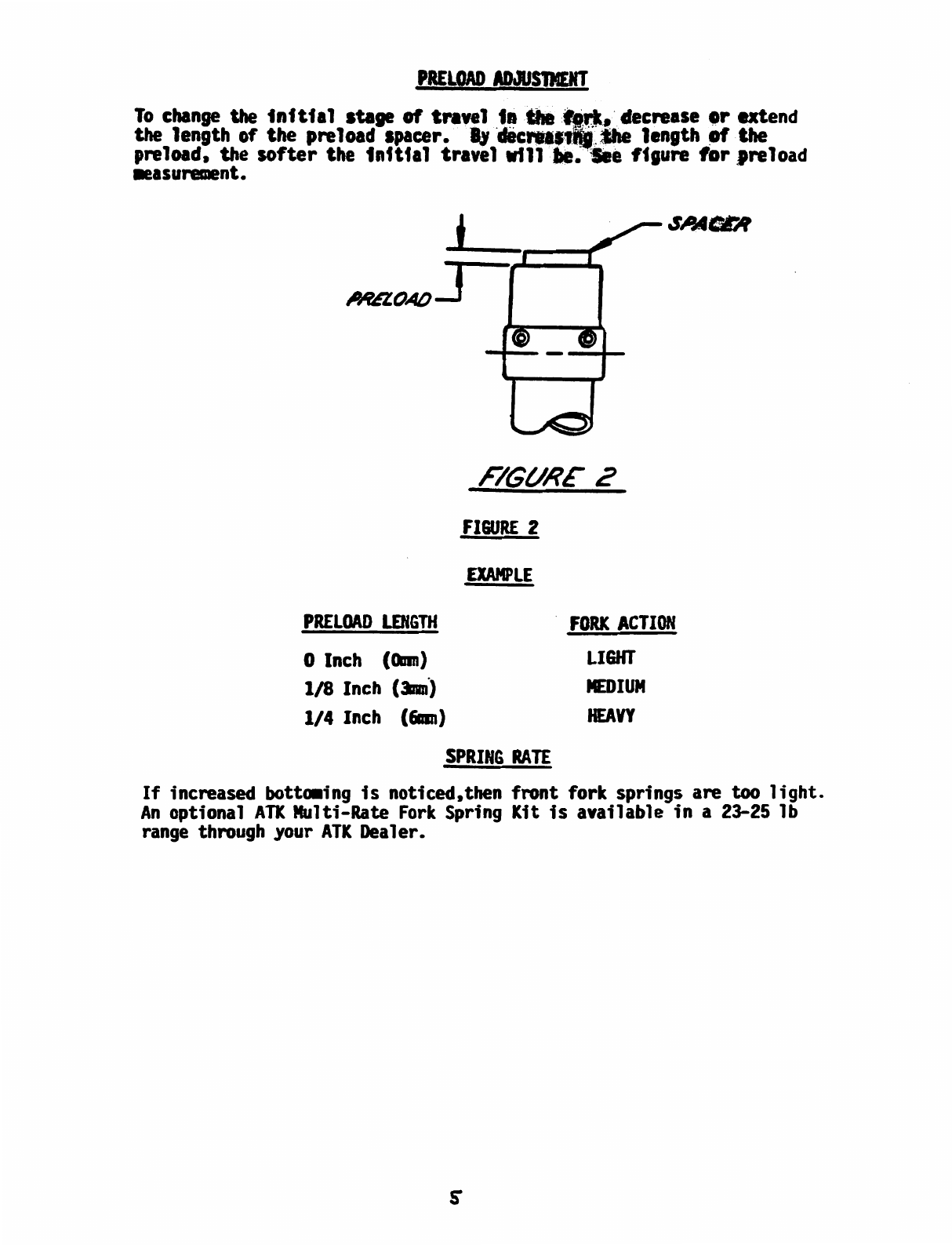
The
rear suspension should sag 2-3 inches
(51-7&mn)
when
sitting
on
the
bike in
nonnal
riding position. This small sag requirement
is
due
to the
A-Trak
chain torque elfminaf:t'r,
which
increases in usable
rear
suspension.
From
our experience
we
recomnend
that
for
motocross racing
2-23f
inches
(51-64nm)
of
sag
is
best .For
trail
riding
use
up
to 3 inches.
Prop
the bike
up
on
a center stand
so
that
the
rear
wheel
is
off
the ground,
thus unloading the
rear
spring of the bikes weight.
Measure
the distance
between
the center
of
the axle to the center
of
the
left
side
na.noer
plates
rear
attactunent screw as
shown
on
figure 4. This distance
is
the extended
travel length.
Take
the bike
off
the stand
and
sit
on
it
in your
normal
riding positon.
Measure
the
new
distance
between
the center
of
the axle
to the center
of
the
left
side
number
plates
rear
attachment screw. This
distance
is
the usable travel length. Subtract the usable travel length
from
the extended travel length
and
the difference
between
the
two
is
the
suspension sag.
EXTENDED
TRAVEL
LEl~GTH
-
USABLE
TRAVEL
LENGTH
EXffNL)ELJ
LENGTH
'OMPRESS£0
~£'NGTH
l
F/Gt/l?E
~
=
SUSPENSION
SAG
CONPllESSION
ALJJf/STE,4
Pl<£L0Af)
AtJ./l/STEll
t t
COMPl?ESSfLJ
LENGTH
'
F!Gt./l?E 5
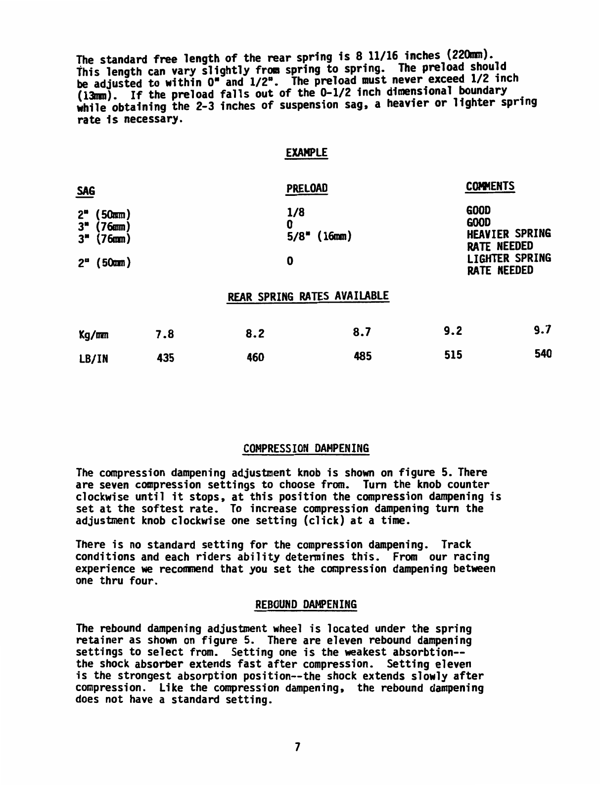
To
achieve your desired suspension
sag
it
will be necessary to adjust
the
rear
shock's preload as
sho~n
on
figure 5.
The
preload equals the
free
length
of
the
rear
spring
minus
the compressed length
of
the
spring.
FREE
LENGTH
-
COMPRESSED
LENGTH
=
PRELOAD
6


 Supplementary service manual")


