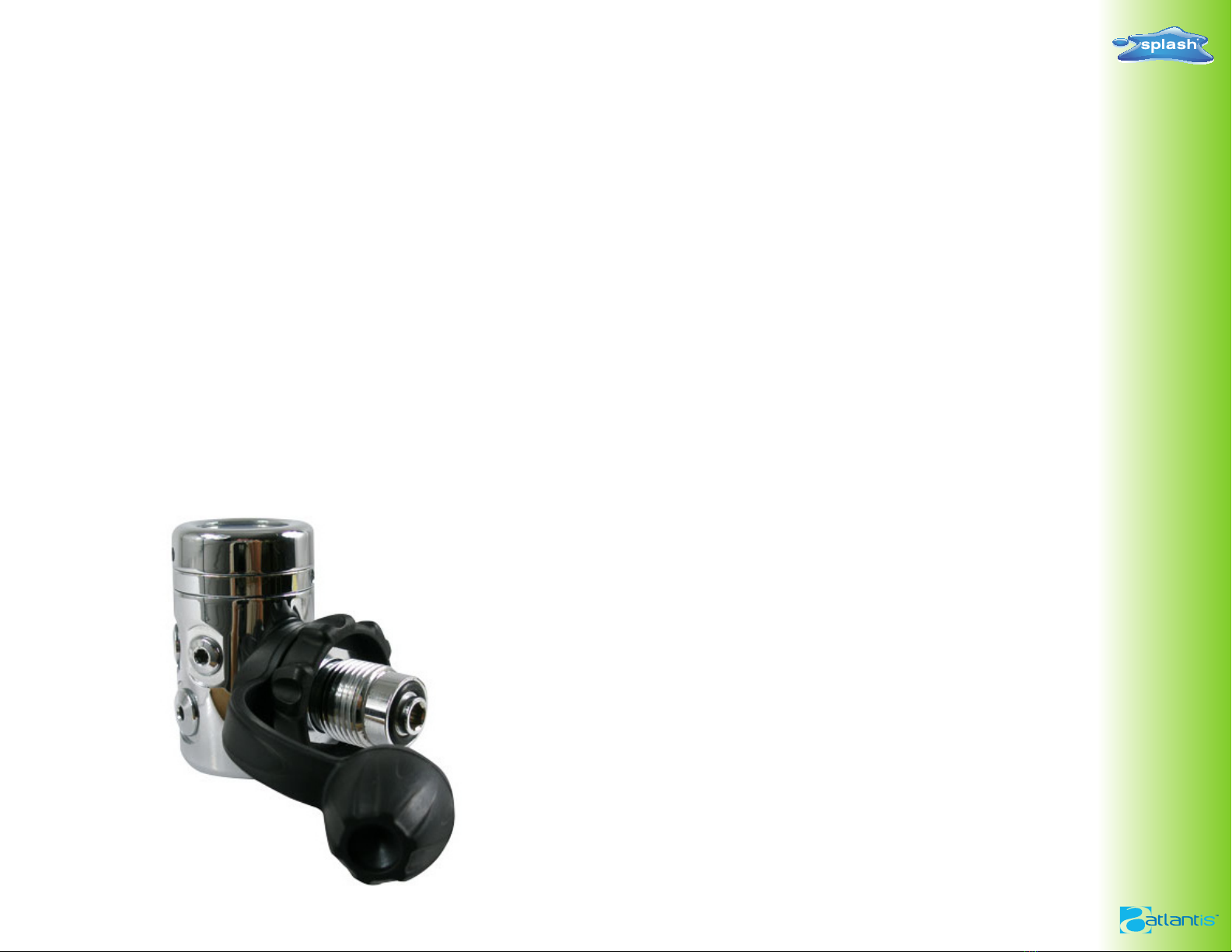
FIRST STAGE REGULATOR
Diaphragm Balanced Regulator 1ST STAGE
‧ Maximum working pressure 35 00psi(232 bar)
‧ Low pressure port swivel assembly for
versatile positioning
‧ Intermediate p ressure 140 PSI
‧ Five 3/8-24 UNF-2B intermediate press ure ports
‧ Two 7/16-20 UNF-2B high pressure ports
‧ Chromium plated brass bod y
‧ Stainless steel springs
‧ YOKE OR DIN
‧ FOR COLD WATER
N O I T E M N O D E S C R I P T I O N Q ' T Y
1 0 1 1 1 Y O K E K N O B 1
2 0 0 5 5 3 5 0 0 P S I Y O K E 1
3 0 1 3 3 Y O K E R E T A I N E R 1
4 0 1 1 3 F I L T E R 1
5 2 - 0 1 1 - 0 2 O - R I N G 1
6 0 1 1 8 D U S T C A P 1
7 0 1 3 2 S T Y L E D I S K 1
8 0 2 3 1 M A I N H O U S I N G 1
9 0 2 2 9 L I F T E R 1
1 0 0 2 0 6 D I A P H R A G M 1
1 2 0 2 0 8 S P R I N G S E A T 1
1 3 0 2 0 9 S P R I N G W A S H E R 2
1 4 0 2 1 0 M A I N S P R I N G 1
1 5 0 2 1 2 A D J U S T S C R E W 1
1 6 0 2 1 3 H P S E A T 1
1 7 0 2 1 5 B A L A N C E S P R I N G 1
1 8 2 - 0 0 6 - 0 2 O - R I N G 1
1 9 2 - 0 1 1 - 0 2 O - R I N G 1
2 0 2 - 0 1 6 - 0 1 O - R I N G 1
2 1 0 2 2 8 B A L A N C E P L U G 1
2 2 3 - 9 0 4 - 0 1 O - R I N G 2
2 3 0 1 0 8 H P P L U G 2
2 4 3 - 9 0 3 - 0 1 O - R I N G 4
2 5 0 1 0 9 L P P L U G 4
2 6 0 1 1 4 D I N H O U S I N G 1
2 7 0 1 1 6 D I N W H E E L 1
2 8 2 - 0 1 2 - 0 2 O - R I N G 1
2 9 0 1 1 5 D I N R E T A I N E R 1
3 0 2 - 1 1 2 - 0 2 O - R I N G 1
3 1 0 2 2 5 D I A P H R A G M C L A M P 1
3 2 0 2 2 3 T R A N S P I S T O N 1
3 3 0 2 2 6 S I L I C O N E D I S K 1
3 4 0 2 2 2 E N V C A P 1
D I A P G R A G M B A L A N C E R E G P A R T L I S T
11 0207 DIAPHRAGMWASHER 1
COLDWATERDIAPHRAGM