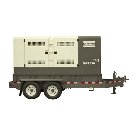
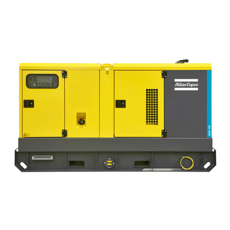
Atlas Copco QAS108 Pd(S) Mk II User manual

Instruction manual.................................................................................................................................3
Bedieningshandleiding...................................................................................................................25
Manuel d'instructions.......................................................................................................................47
Bedienungsanleitung.......................................................................................................................69
Libro de instrucciones.....................................................................................................................91
Instruktionsbok ..................................................................................................................................113
Manuale di istruzioni......................................................................................................................135
Instruksjonsbok .................................................................................................................................157
Betjeningsvejledning ....................................................................................................................179
BÈ‚Ï›Ô Ô‰ËÁÈÒÓ.....................................................................................................................................201
Manual de instruções ..................................................................................................................223
Siirrettävien.............................................................................................................................................245
Parts list – Onderdelenlijst – Liste de pièces – Ersatzteilliste –
Lista de las partes – Reservdelsförteckning – Listino parti di
ricambio – Deleliste – Reservedelsliste – K·Ù¿ÏÔÁÔ˜
EÍ·ÚÙËÌ¿ÙˆÓ – Lista de peças – Osaluettelo..........................................................343
Glossary– Woordenlijst – Glossaire – Glossar – Glosario –
Ordlista – Glossario – Ordliste – Ordliste – °ÏˆÛÛ·ÚÈÔ –
Glossário – Sanasto.........................................................................................................................425
Instruction Manual
for AC Generators
QAS108 Pd(S) Mk II
Registration code
Collection : APC Q
Tab : 38
Printed matter N°
2950 0542 00
1997 – 04
PAGE
ATLAS COPCO – PORTABLE AIR DIVISION
B-2630 AARTSELAAR BELGIUM
2950 0542 00 EN

2
QAS108 Pd(S) Mk II

3
INSTRUCTION MANUAL
Congratulations on the purchase of your QAS108 AC gene-
rator. It is a solid, safe and reliable machine, built according
to the latest technology. Follow the instructions in this book-
let and we guarantee you years of troublefree operation.
Please read the following instructions carefully before start-
ing to use your machine.
While every effort has been made to ensure that the infor-
mation in this manual is correct, Atlas Copco does not as-
sume responsibility for possible errors. Atlas Copco re-
serves the right to make changes without prior notice.
CONTENTS
Safety precautions for generators QAS...............................................................4
Leading particulars............................................................................................................................................5
General description.........................................................................................................................................5
Bodywork.............................................................................................................................................................................6
Markings...............................................................................................................................................................................6
Drain plugs and filler caps.................................................................................................................6
Battery switch..............................................................................................................................................................6
Control and indicator panel..............................................................................................................6
Output terminal board.................................................................................................................................8
Operating instructions...............................................................................................................................8
Installation..........................................................................................................................................................................8
Connecting the generator....................................................................................................................9
Before starting.......................................................................................................................................................10
Starting................................................................................................................................................................................10
During operation...............................................................................................................................................10
Stopping...........................................................................................................................................................................10
Maintenance.................................................................................................................................................................11
Maintenance schedule..........................................................................................................................11
Measuring the alternator insulation resistance........................................11
Engine maintenance..................................................................................................................................11
Storage of the generator...................................................................................................................12
Storage................................................................................................................................................................................12
Preparing for operation after storage........................................................................12
Checks and trouble shooting.................................................................................................12
Checking voltmeter P4..........................................................................................................................12
Checking frequencymeter P5..................................................................................................12
Checking ammeters P1, P2 and P3..............................................................................12
Alternator trouble shooting............................................................................................................13
Engine trouble shooting......................................................................................................................13
Options available for QAS108 units.........................................................................15
Overview of the electrical options....................................................................................15
Description of the electrical options............................................................................15
Overview of the mechanical options...........................................................................21
Description of the mechanical options...................................................................21
Technical specifications....................................................................................................................23
Readings on gauges.................................................................................................................................23
Settings of switches....................................................................................................................................23
Specifications of the engine/alternator/unit....................................................23
Specifications of the options......................................................................................................23
Circuit diagrams..............................................................................................................................................267

SAFETY PRECAUTIONS FOR GENERATORS QAS
Everyone who uses or maintains Atlas Copco equipment is expected to read the
following safety precautions attentively and to act accordingly before installing,
operating or repairing the generators.
The operator must employ safe working practices and observe all relevant local
safety requirements.
The owner is responsible for maintaining the unit in a safe operating condition.
Parts and accessories shall be replaced if unsuitable for safe operation.
Installation, operation, maintenance and repair shall only be carried out by
authorized, competent personnel.
Any modification on the unit shall only be performed in agreement with Atlas
Copco and under supervision of authorized, competent personnel.
If any statement in this book, especially with regard to safety, does
not comply with local legislation, the stricter of the two shall apply.
Ignoring these safety precautions may result in injury or death of the
operator and/or people in the vicinity.
In addition to normal safety rules which must be observed with generators, the
following safety precautions listed hereafter are stressed.
INSTALLATION PRECAUTIONS
1. Generators shall be lifted only with adequate equipment in conformity with local safety
rules. Loose or pivoting parts shall be securely fastened before lifting. It is forbidden to
stay in the risk zone under a lifted load. Lifting acceleration and retardation shall be kept
within safe limits.
2. The aspirated air shall be free from flammable or toxic fumes, e.g. paint solvents, that can
lead to internal fire or explosion.
3. Generators shall be installed on an even, solid floor, in a clean location with sufficient
ventilation. If the floor is not level or can vary in inclination, consult Atlas Copco. If the
unit is installed on a trailer, immobilize the trailer and chock the wheels.
4. The engine exhaust is a lethal gas. Do not operate the unit in a confined, not-ventilated
room.
5. Never remove or tamper with the safety devices, guards or insulations fitted on the
machine.
6. The electrical connections shall correspond to the local codes. The machines shall be
earthed and protected against short circuits by fuses or circuit breakers.
7. Damaged cables and insufficient tightening of connections may cause electric shocks.
Replace damaged cables and make sure that all electric connections are securely tightened.
OPERATION PRECAUTIONS
1. Operate the unit as described in the Instruction book to ensure safe, efficient operation.
2. Never operate the generator in excess of its limits as indicated in the technical
specifications and avoid long no-load sequences.
3. Never operate the generator in a humid atmosphere. Excessive moisture causes worsening
of the generator insulation.
4. Never touch the power terminals during operation of the machine.
5. Keep all bodywork doors shut during operation. The doors may be opened for short
periods only, e.g. to carry out routine checks. Wear ear protectors when opening a door.
6. People staying in environments or rooms where the sound pressure level reaches or
exceeds 90 dB(A) shall wear ear protectors.
7. Periodically check that:
a. All guards are in place and securely fastened.
b. All hoses, cables and/or pipes inside the generator are in good condition, secure and
not rubbing.
c. There are no leaks.
d. All fasteners are tight.
e. All electrical wirings are secure and in good order.
8. Do not remove any of, or tamper with, the sound-damping material.
9. Whenever an abnormal condition arises, e.g. excessive vibration, noise, odour, etc., switch the
circuit breakers to OFF and stop the engine. Correct the faulty condition before re-starting.
10. Never refill fuel while the machine is running. Keep fuel away from hot pipes. Never
smoke while fuelling. Do not spill or leave fuel, oil, coolant or cleansing agent in or
around the unit.
11. Keep flammable material away from the machine. If required, provide a spark arrestor to
trap incendiary exhaust sparks.
12. Earth the generator as well as the load properly.
13. Check the electric cables regularly. Whenever damaged wires or dangerous conditions are
observed, switch the circuit breakers to OFF and stop the engine. Replace the damaged
wires or correct the dangerous condition before re-starting.
14. Avoid overloading the generator. The generator is provided with circuit breakers for
overload protection. When a breaker has tripped, reduce the concerned load before re-
starting.
15. If the generator is used as stand-by for the mains supply, it must not be operated without
control system which automatically disconnects the generator from the mains when the
mains supply is restored.
16. Never remove the cover of the output terminals during operation. Before connecting or
disconnecting wires, switch off the load and the circuit breakers, stop the machine and
make sure that the machine cannot be started inadvertently or there is any residual voltage
on the power circuit.
17. Never connect the generator outlets to an installation which is also connected to a public
mains.
18. Before connecting a load, switch off the corresponding circuit breaker, and check whether
frequency, voltage, current and power factor comply with the ratings of the generator.
19. Running the generator at low load for long periods will reduce the lifetime of the engine.
20. Diesel engine exhaust and some of its constituents are known to the State of Califorina to
cause cancer, birth defects, and other reproductive harm.
MAINTENANCE PRECAUTIONS
1. Use only the correct tools for maintenance and repair work.
2. Use only genuine spare parts.
3. All maintenance work, other than routine attention, shall only be undertaken when the
generator is stopped and when all loads are disconnected from the machine. Ensure that
the machine cannot be started inadvertently.
4. Scrupulously observe cleanliness during maintenance and repair. Keep dirt away by
covering the parts and exposed openings with a clean cloth, paper or tape.
5. Protect the air filter, electrical and regulating components, etc. to prevent moisture from
entering them, e.g. when cleaning. Take care that moisture does not penetrate any
component.
6. Never remove a filler cap of the cooling water system of a hot engine. Wait until the engine
has sufficiently cooled down.
7. Never use flammable solvents or carbon tetrachloride for cleaning parts. Take safety
precautions against toxic vapours of cleaning liquids.
8. Take precautions against fire. Handle fuel, oil and anti-freeze with care because they are
inflammable substances. Do not smoke or approach with naked flame when handling such
substances. Keep a fire-extinguisher in the vicinity.
9. Make sure that no tools, loose parts or rags are left in or on the generator. Never leave rags
or loose clothing near the engine air intake.
10. Before clearing the generator for use after maintenance or overhaul, submit it to a testrun,
check that the AC power performance is correct and that the control and shut-down devices
function correctly.
11. When servicing batteries, always wear protecting clothing and glasses. The electrolyte is a
sulphuric acid which can cause severe burns. When charging batteries, an explosive gas
forms above the cells and escapes through the vents. Do not smoke near batteries being,
or recently having been charged. Never break live circuits or battery terminals, because a
spark usually occurs.
12. Make sure that all sound-damping material is in good condition. If damaged, replace it by
genuine Atlas Copco material to prevent the sound pressure level from increasing.
4
QAS108 Pd(S) Mk II
!
CALIFORNIA
Proposition 65 Warning
Diesel engine exhaust and some of its
constituents are known to the State of
California to cause cancer, birth
defects, and other reproductive harm.

5
INSTRUCTION MANUAL
LEADING PARTICULARS
GENERAL DESCRIPTION
The QAS108 is an AC generator, built for continuous running
at sites where no electricity is available or as stand-by in
cases of interruption of the mains.
The generator operates at 50 Hz, 230 V in line-to-neutral
mode and 400 V in line-to-line mode. The rated output is
100 kVA.
The QAS108 generator is driven by a water-cooled turbo
charged diesel engine, manufactured by PERKINS.
An overview of the main parts is given in the diagram below.
1 Lifting rod
2 Guiding rod
3 Side doors, access to engine and alternator
4 Engine exhaust
5 Data plate
6 Earthing rod
7 Side door, access to control and indicator panel
8 Output terminal board
9 Hole for forklift
A Alternator
AF Air filter
C Coupling
DFO Drain flexible engine oil
DFW Drain flexible cooling water
DH Drain and access hole (in the frame)
DPF Drain plug fuel
E Engine
F Fan
FCF Filler cap fuel
FCO Filler cap engine oil
FCW Filler cap cooling water
FF Fuel filter
FPF Fuel pre-filter
G1 Battery
OF Oil filter
OLD Engine oil level dipstick
S1 Battery switch
0
1
diesel
2
1
DPF
5
ATLASCOPCOAIRPOWER n.v.
1200 Kg
S
1N
N
N
N
N
Hz
kVA
kW
V
COP
COP
3/N/PE
A
P
V
I
1994
49
400/230
27
34
50
cosphi cl. G2.
MADEBYATLASCOPCOAIRPOWER n.v. WILRIJK BELGIUM
1615694500
-YA 3 - 606035 - x x x x x x -
G1
99 6
OLD
C
DFO
OF
4FCW
FF FCOAF E F
S1
DFW
A
FCW
DH
39 9
7 8
FCF
100
FPF

BODYWORK
The alternator, the engine, the cooling system, etc. are
enclosed in a sound-insulated bodywork that can be opened
by means of side doors (and service plates).
The recess in the roof has a lifting rod in the middle and a
guiding rod at both sides.
Never use the guiding rods to lift the generator.
To be able to lift the QAS108 by means of a forklift,
rectangular holes are provided in the frame. The earthing rod,
connected to the generator’s earth terminal is located at the
side of the frame.
MARKINGS
A brief description of all markings provided on the QAS108 is
given hereafter.
Indicates that an electric voltage, dangerous to
life, is present. Never touch the electric terminals
during operation.
Indicates that the engine exhaust is a hot and
harmful gas, which is toxic in case of inhalation.
Always make sure that the unit is operated
outside or in a well-ventilated room.
Indicates that these parts can become very hot
during operation (eg. engine, cooler, etc.).
Always make sure that these parts are cooled
down before touching them.
Indicates that the guiding rods may not be used
to lift the generator. Always use the lifting rod in
the roof of the generator to lift it.
Indicates that the generator may be refueled
with diesel fuel only.
Indicates the drain hole for the engine oil.
Indicates the drain hole for the coolant.
Indicates the drain plug for the engine fuel.
Indicates the different earthing connections on
the generator.
Indicates the lifting eye of the generator.
Indicates that the unit may start auto-
matically.
Indicates the 3-way valve.
Indicates the battery switch.
DRAIN PLUGS AND FILLER CAPS
The drain holes for the engine oil, the coolant and the plug for
the fuel, are located and labelled on the frame; the fuel drain
plug at the front, the others at the service side.
The drain flexible for engine oil can be brought to the outside
of the generator through the drain hole.
The drain hole can also be used to guide external fuel tank
connections. When connecting an external fueltank, use the 3-
way valves. Refer to the option “External fueltank connection”.
The filler cap for the engine coolant is accessible via an
opening in the roof. The fuel filler cap is located in the side
panel.
BATTERY SWITCH
The battery switch is situated inside the sound-insulated
bodywork. It allows to open or to close the electrical
connection between the battery and the engine circuits.
Never turn the battery switch off while the engine is running.
CONTROL AND INDICATOR PANEL
The control and indicator panel is located behind a door in
the side panel. The hinged door is partly transparent and
allows easy access to the parts mounted behind it. Panel
light H1 goes on as soon as the starter switch is turned into
position I.
Engine gauges
P6 .....Hourmeter
P7 .....Fuel level gauge
P8 .....Engine coolant temperature gauge
P9 .....Engine oil pressure gauge
P10 ...Battery voltage gauge
P7 and P10 are combined in one instrument, as well as P8
and P9.
6
QAS108 Pd(S) Mk II
!
P7
60/5A I
ME
0
20
60
40
L3
A
I
ME
0
200
100
500
300
400
V
60/5A I
ME
0
20
60
40
L3
A
60/5A I
ME
0
20
60
40
L3
A
55
65
50
45
60
ORORS
SO
TOTR
ST
RPM
ZERO AT DOT
Hz
1400
1500
1600
1700
1800
1900
1954
VDO
F
EHz >
°C
bar
V
VDO
h
P10 P8P9
F4 P6 P4 P5S4
ST P1 P2H1 P3
diesel
!
!
!

7
INSTRUCTION MANUAL
Generator gauges
P1 .....Ammeter line L1
Indicates the outgoing current in the first phase (L1).
P2 .....Ammeter line L2
Indicates the outgoing current in the second phase (L2).
P3 .....Ammeter line L3
Indicates the outgoing current in the third phase (L3).
P4 .....Voltmeter
Indicates the voltage selected by means of voltage selector
switch S4.
P5 .....Frequency / RPM meter
Indicates the frequency of the supply voltage and the speed of
the engine.
S4 .....Voltmeter selector switch
Allows to measure the voltage between each of the phases
and between each phase and the neutral. It also allows to
switch off the voltmeter.
Engine controls and lamps
ST .....Starter switch
The starter switch is a three-position switch.
O : the voltage supply from the battery is switched off.
I : the electrical system of the engine, except the starting
circuit is energized.
: the starter motor is energized. As soon as the engine
fires, the switch can be released. The switch automatically
returns to position I.
After approximately 20 seconds in position without star-
ting, the control system will automatically shut down (battery
saving purpose) indicating a low oil pressure failure. In this
case, a reset of the control system by putting the switch in
position O is necessary.
F4......Fuse
The fuse activates when the current from the battery to the
engine control circuit exceeds its setting. The fuse can be
switched on and off by pushing the button.
L1......Electrical system indicator
Lights up when the electrical system of the engine is
energized.
L2......Engine preheating system indicator
Lights up when the glow plugs in the engine, used to facilitate
starting, are warming up. Extinguishes after approximately 10
seconds. Bypassing of the preheattime is allowed e.g. when
starting a hot engine, but the preheat system remains active.
L3......Alternator charging indicator
Goes out after starting, indicating that the alternator is char-
ging. A failing alternator however will not shut the engine
down.
L4......AC shutdown indicator
Lights up when no AC input (<160 V line-to-neutral) is present.
L5......Overspeed shutdown indicator
Lights up when the engine’s speed has exceeded 115 % of
the nominal speed. The nominal speed is determined by
means of the dipswitch at the back of the control module
(50 Hz or 60 Hz).
L6......Engine coolant temperature fault indicator
Lights up when the high engine coolant temperature was the
cause of shutdown.
L7......Engine oil pressure fault indicator
Lights up when the low engine oil pressure was the cause of
shutdown.
L8......Spare shutdown indicator
Can be used to wire an extra shutdown, e.g. for low fuel level
in case a switch is incorporated in the fuel tank.
F4
Hz >
L1
L2
L3
L4
L5
L6
L7
L8
ST
!

8
QAS108 Pd(S) Mk II
OUTPUT TERMINAL BOARD
The output terminal board is situated below the control and
indicator panel.
N13...Earth leak detector
Detects and indicates an earth fault current and activates the
main circuit breaker Q1. The detection level can be set at
0.03 A fixed with instantaneous trip but can also be adjusted
between 0.1 A and 1 A with time delayed (0 – 0.5 sec) trip. N13
has to be reset manually after eliminating the problem (reset
button marked R). It can be overridden by means of the earth
leak switch (S13, labelled I∆N) but has to be tested monthly
(by pushing test button T).
S2 .....Emergency stop button
Push the button to stop the generator in case of an emer-
gency. When the button is pressed, it must be unlocked, by
turning it anti-clockwise, before the generator can be restarted.
Q1.....Main circuit breaker and minimum voltage relay
Interrupts the power supply to X1 when a short-circuit occurs
at the load side, or when the overcurrent protection (145 A) is
activated. When activated, Q1 interrupts the three phases
towards X1. It can be activated again after eliminating the
problem.
X1 .....Main power supply (400 V AC)
Terminals L1, L2, L3, N (= neutral) and PE (= earthing), hidden
behind the control panel door and behind a small transparent
door.
OPERATING INSTRUCTIONS
In your own interest, always strictly observe all relevant safety
instructions.
Do not operate the generator in excess of the limitations
mentioned in the Technical Specifications.
Local rules concerning the setting up of low voltage power
installations (below 1,000 V) must be respected when
connecting site distribution panels, switch gear or loads to the
generator.
At each start-up and at any time a new load is connected, the
earthing of the generator must be verified. Earthing must be
done either by the earthing rod or, if available, by an existing,
suitable earthing installation. The protective system against
excessive contact voltage is not effective unless a suitable
earthing is made.
The generator is wired for a TN-system to IEC 364-3, i.e. one
point in the power source directly earthed - in this case the
neutral. The exposed conductive parts of the electric
installation must be directly connected to the functional earth.
If operating the generator in another power system, e.g. an IT-
system, other protective devices required for these types must
be installed. In any case only a qualified electrician is
authorized to remove the connection between the neutral (N)
and earth terminals in the terminal box of the alternator.
INSTALLATION
– Place the generator on a horizontal, even and solid floor.
–Protect the generator against dust and rain if it is operated
outside.
–Check that the engine exhaust is not directed towards
people. If the generator is operated indoors, install an
exhaust pipe of sufficient diameter to duct the engine
exhaust towards the outside. Check for sufficient ven-
tilation so that the cooling air is not recirculated. If
necessary, consult Atlas Copco.
–Leave enough space for operation, inspection and mainte-
nance (at least 1 meter at each side).
–Check that the inner earthing system is in compliance with
the local legislation.
–Install the earthing rod as near as possible to the generator
and measure its diffusion resistance (max. 1 KΩ) in order
not to have a contact voltage higher than 25 V at 30 mA
leakage current.
–Check that the cable end of the earthing rod is connected
to the earth terminal.
–Use coolant for the engine cooling system. If low
temperatures are expected (close to 0 °C), the engine
cooling system must be protected (refer to the Engine
instruction book).
– Check the tightness of the bolts and nuts.
!
L1 L2 L3 N PE
Q1
X1
S2
T
10,1
0,5
IAn(A)
0,03>0,1A
N13
A
500 0
250
ms
ATS

9
INSTRUCTION MANUAL
CONNECTING THE GENERATOR
Precautions for non-linear and sensitive loads
Non-linear loads draw currents with high contents in
harmonics, causing distortion in the wave form of the voltage
generated by the alternator.
The most common non-linear, 3-phase loads are thyristor/
rectifier-controlled loads, such as convertors supplying
voltage to variable speed motors, uninterruptable power
supplies and Telecom supplies. Gas-discharge lighting
arranged in single-phase circuits generate high 3rd
harmonics and risk for excessive neutral current.
Loads most sensitive to voltage distortion include incande-
scent lamps, discharge lamps, computers, X-ray equipment,
audio amplifiers and elevators.
Consult Atlas Copco for measures against the adverse
influence of non-linear loads.
Quality, minimum section and maximum length of cables
The cable connected to the terminal board of the generator
must be selected in accordance with local legislation. The
type of cable, its rated voltage and current carrying capacity
are determined by installation conditions, stress and ambient
temperature. For flexible wiring, rubber-sheathed, flexible
core conductors of the type H07 RN-F (Cenelec HD.22) or
better must be used.
The following table indicates the maximum allowable 3-phase
currents (in A), in an ambient temperature of 40 °C, for cable
types (multiple and single core PVC insulated conductors
and H07 RN-F multiple core conductors) and wire sections as
listed, in accordance with VDE 0298 installation method C3.
Local regulations remain applicable if they are stricter than
those proposed below.
Wire section (mm
2
)
2,5 4 6 10 16 25 35 50 70 95
Max. current (A)
Multiple core 22 30 38 53 71 94 114 138 176 212
Single core 25 33 42 57 76 101 123 155 191 228
H07 RN-F 21 28 36 50 67 88 110 138 170 205
The lowest acceptable wire section and the corresponding
maximum cable or conductor length for multiple core cable
or H07 RN-F, at rated current (145 A), for a voltage drop e
lower than 5 % and at a power factor of 0.80, are respectively
50 mm 2and 210 m. In case electric motors must be started,
oversizing the cable is advisable.
The voltage drop across a cable can be determined as
follows:
e= Voltage drop (V)
I = Rated current (A)
L = Length of conductors (m)
R = Resistance (Ω/km to VDE 0102)
X = Reactance (Ω/km to VDE 0102)
Connecting the load
Site distribution panel
If outlet sockets are required, they must be mounted on a site
distribution panel supplied from the terminal board of the
generator and in compliance with local regulations for power
installations on building sites.
Protection
For safety reasons, it is necessary to provide an isolating
switch or circuit breaker in each load circuit. Local legislation
may impose the use of isolating devices which can be locked.
–Check whether frequency, voltage and current comply
with the ratings of the generator.
–Provide for the load cable, without excessive length, and
lay it out in a safe way without forming coils.
–Open the door of the control and indicator panel and the
transparent door in front of the terminal board X1.
–Provide the wire ends with cable lugs suited for the cable
terminals.
–Loosen the cable clamp and push the wire ends of the
load cable through the orifice and clamp.
–Connect the wires to the proper terminals (L1, L2, L3, N
and PE) of X1 and tighten the bolts securely.
– Tighten the cable clamp.
– Close the transparent door in front of X1.
!
!
e =3.I.L.(R.cosϕ+ X.sinϕ)
1000

10
QAS108 Pd(S) Mk II
BEFORE STARTING
–With the generator standing level, check the engine oil
level and top up if necessary. The oil level must be near to,
but not exceed the high mark on the engine oil level
dipstick.
–Check the coolant level in the expansion tank of the engine
cooling system. The water level must be near to the FULL
mark. Add coolant if necessary.
–Drain any water and sediment from the fuel pre-filter.
Check the fuel level and top up if necessary. It is recom-
mended to fill the tank after the day’s operation to prevent
waterdamp in a nearly empty tank from condensing.
–Check the vacuum indicator of the air filter. If the red part
shows completely, replace the filter element.
– Press the vacuator valve of the air filter to remove dust.
–Check the generator for leakage, tightness of wire termi-
nals, etc. Correct if necessary.
–Check that circuit breaker Q1 is switched off.
–Check that fuse F4 is not activated and that the emer-
gency stop is in the “OUT” position.
– Check that the load is switched off.
STARTING
– Turn the battery switch to ON.
–Put the starter switch in position I. The instrument panel
lights light up, the fuel solenoid is energized and the
preheating of the engine starts. After approximately 10
seconds, the preheat lamp on the engine control module
goes out.
–Push down the starter switch into position and release it
as soon as the engine fires. The switch automatically
returns to position I.
Do not keep the switch in its utmost position for more than 10
seconds (maximum 20 seconds in extremely cold conditions).
Wait two minutes between each starting attempt.
When the ambient temperature is below 0°C, start the engine
as follows: put the starter switch in position I until the preheat
lamp goes out. Put the switch back into position O and then
immediately put it into position . Release the switch as
soon as the engine fires.
If the engine fails to start and for starting in extremely cold
conditions, consult your local Atlas Copco dealer.
–Check that the warning lamps on the control and indicator
panel are out.
–Run the engine for approximately 5 minutes to warm up.
Check the engine oil pressure (P9) and the cooling water
temperature (P8).
–Check the voltmeter P4 (with voltmeter selector switch S4
in different positions) and the frequency meter P5.
– Switch circuit breaker Q1 to off and then to on.
–Switch on the load and check the ammeters P1, P2 and
P3, voltmeter P4 (voltmeter selector switch in different
positions) and frequency meter P5.
DURING OPERATION
Following points should be carried out regularly:
–Check the engine gauges and the lamps for normal
readings.
Avoid to let the engine run out of fuel. If it happened, priming
will speed up the starting.
– Check for leakage of oil, fuel or cooling water.
–Avoid long low-load periods. In this case, an output drop
and higher oil consumption of the engine could occur.
–Check, by means of the generator gauges, that the voltage
between the phases is identical and that the rated current
per phase is not exceeded.
–When single-phase loads are connected to the generator
output terminals, keep all loads well-balanced.
Never turn the battery switch to OFF during operation.
If circuit breaker Q1 is activated during operation, switch off
the load and stop the generator. Check and, if necessary,
decrease the load.
The generator’s side doors may only remain opened for short
periods during operation, to carry out checks for example.
STOPPING
– Switch off the load.
– Switch off circuit breaker Q1.
– Let the engine run for about 5 minutes.
– Stop the engine by putting the starter switch in position O.
– Turn the battery switch to OFF.
–Lock the side doors and the door of the indicators and
control panel to avoid unauthorized access.
!
!
!

MAINTENANCE
Before carrying out any maintenance activity, check that the start switch is in position O and that no electrical power is present on the
terminals.
MAINTENANCE SCHEDULE Daily Initial Small Normal Yearly
50 hours 250 hours 500 hours 2000 hours
SERVICE PAK – With unit 2912 4264 05 2912 4265 06 2912 4266 07
For the most important subassemblies, Atlas Copco has developed service kits that combine all wear parts. These service kits offer you the
benefits of genuine parts, save on administration costs and are offered at reduced price, compared to the loose components. Refer to figure
1 of the parts list for more information on the contents of the service kits.
Coolant level Check Check Check Check Check
Tension and condition of drive belt(s) Check Check Check Replace
Radiator and intercooler fins Check/Clean Check/Clean Check/Clean Check/Clean
Fuel pre-filter/Water separator Check/Drain Check/Drain Check/Drain Check/Drain Check/Drain
Fuel filter element Replace Replace Replace Replace
Fuel injectors Check
Oil level in sump Check Check Check Check Check
Oil pressure on gauge Check Check Check Check Check
Lubrication oil Change Change Change Change
Oil filter(s) Replace Replace Replace Replace
Air cleaner and dust bowl Clean Clean Clean Clean
Air filter element (1) Clean Replace Replace
Safety cartridge Replace
Valve clearance Check/adjust Check/adjust Check/adjust Check/adjust
Oil, fuel and water leaks Check Check Check Check
Mechanical links (e.g. fuel solenoid link) Grease Grease Grease
Level battery electrolyte (2) Check Check Check Check
Condition of vibration dampers Check Check Check Check
Alternator insulation resistance (*) Measure Measure Measure Measure
Tightness of nuts and bolts Check Check
Door hinges and locks Grease Grease
Fixation of hoses, cables and pipes Check Check
Inspection by Atlas Copco Service technician
11
INSTRUCTION MANUAL
(1) More frequently when operating in a dusty environment.
Evacuate dust from the airfilter valve daily.
(2) A Service Bulletin (ASB) dealing elaborately with batteries and
due care is available on request.
ENGINE MAINTENANCE
Refer to the engine’s operator manual for full maintenance,
including instructions for changing the oil and cooling water
and replacing the fuel, oil and air filters.
(*) MEASURING THE ALTERNATOR INSULATION RESISTANCE
A 500-V megger is required to measure the alternator
insulation resistance.
If the N-terminal is connected to the earthing system, it must
be disconnected from the earth terminal. Disconnect the
AVR.
Connect the megger between the earth terminal PE and
terminal L1 and generate a voltage of 500 V. The scale must
indicate a resistance of at least 5 MΩ.
Refer to the alternator operating and maintenance instruc-
tions for more details.
!
!

12
QAS108 Pd(S) Mk II
STORAGE OF THE GENERATOR
STORAGE
–Store the generator in a dry, frost-free room which is well
ventilated.
–Run the engine regularly, e.g. once a week, until it is
warmed up. If this is impossible, extra precautions must be
taken:
–Consult the engine’s operator manual.
–Remove the battery. Store it in a dry, frost-free room.
Keep the battery clean and its terminals lightly covered
with petroleum jelly. Recharge the battery regularly.
–Clean the generator and protect all electrical compo-
nents against moisture.
–Place silica gel bags, VCI paper (Volatile Corrosion
Inhibitor) or another drying agent inside the generator
and close the doors.
–Stick sheets of VCI paper with adhesive tape on the
bodywork to close off all openings.
–Enclose the generator, except the bottom, with a plastic
bag.
PREPARING FOR OPERATION AFTER STORAGE
Before operating the generator again, remove the wrapping,
VCI paper and silicagel bags and check the generator
thoroughly (go through the checklist “Before starting”).
– Consult the engine’s operator manual.
–Check that the insulation resistance of the generator ex-
ceeds 5 MΩ.
–Replace the fuel filter and fill the fuel tank. Vent the fuel
system.
–Reinstall and connect the battery, if necessary after being
recharged.
–Submit the generator to a test run.
CHECKS AND TROUBLE SHOOTING
Never perform a test run with connected power cables. Never
touch an electrical connector without a voltage check.
When a failure occurs, always report what you experienced
before, during and after the failure. Information with regard to
the load (type, size, power factor, etc.), vibrations, exhaust
gas colour, insulation check, odors, output voltage, leaks and
damaged parts, ambient temperature, daily and normal
maintenance and altitude might be helpful to quickly locate the
problem. Also report any information regarding the humidity
and location of the generator (eg. close to sea).
CHECKING VOLTMETER P4
–Put a voltmeter in parallel with voltmeter P4 on the control
panel.
–Check that the read-out of both voltmeters is the same.
– Stop the generator and disconnect one terminal.
– Check that the internal resistance of the voltmeter is high.
CHECKING FREQUENCYMETER P5
– Run the unit at normal speed.
– Put a voltmeter in parallel with frequencymeter P5.
–If the measured voltage is higher than 200 V, the frequen-
cymeter has to work properly.
If not, remove the frequencymeter, connect it with the
mains (230 V) and check that it indicates 50 Hz.
CHECKING AMMETERS P1, P2 AND P3
–Measure by means of a clamp-on probe the current,
during the load.
–Compare the measured currents with the currents indi-
cated on the corresponding ammeters. Both readings
should be the same.
!

ENGINE TROUBLE SHOOTING
The table below gives an overview of the possible engine
problems and their possible causes.
The starter motor turns the engine too slowly
– Battery capacity too low.
– Bad electrical connection.
– Fault in starter motor.
– Wrong grade of lubricating oil.
The engine does not start or is difficult to start
– Starter motor turns engine too slowly.
– Fuel tank empty.
– Fault in fuel control solenoid.
– Restriction in a fuel pipe.
– Fault in fuel lift pump.
– Dirty fuel filter element.
– Air in fuel system.
– Fault in atomisers.
– Cold start system used incorrectly.
– Fault in cold start system.
– Restriction in fuel tank vent.
– Wrong type or grade of fuel used.
– Restriction in exhaust pipe.
Not enough power
– Restriction in a fuel pipe.
– Fault in fuel lift pump.
– Dirty fuel filter element.
– Restriction in air filter/cleaner or induction system.
– Air in fuel system.
– Fault in atomisers or atomisers of an incorrect type.
– Restriction in fuel tank vent.
– Wrong type or grade of fuel used.
– Restricted movement of engine speed control.
– Restriction in exhaust pipe.
– Engine temperature is too high.
– Engine temperature is too low.
13
INSTRUCTION MANUAL
ALTERNATOR TROUBLE SHOOTING
Symptom
Alternator does not excite.
After being excited alternator
does not excite.
Low voltage at no load.
High voltage at no load.
Lower than rated voltage at
load.
Higher than rated voltage at
load.
Unstable voltage.
Possible cause
Blown fuse.
Insufficient residual voltage.
No residual voltage.
Connections are interrupted.
Voltage potentiometer out of setting.
Intervention of protection.
Winding failure.
Voltage potentiometer out of setting.
Failed regulator.
Voltage potentiometer out of setting.
Intervention by protection.
Failed regulator.
Rotating bridge failure.
Voltage potentiometer out of setting.
Failed regulator.
Speed variation in engine.
Regulator out of setting.
Corrective action
Replace fuse.
Increase the speed by 15 %.
For an Instant apply on the + and – terminals of the electronic
regulator a 12 V battery voltage with a 30 Ωresistor in series
respecting the polarities.
Check connection cables as per attached drawings.
Reset voltage.
Check rpm.
Check windings.
Reset voltage.
Substitute regulator.
Reset voltage potentiometer.
Current too high, power factor lower than 0.8; speed lower
than 4% of rated speed.
Substitute regulator.
Check diodes, disconnect cables.
Reset voltage potentiometer.
Substitute regulator.
Check regularity of rotation.
Regulate stability of regulator by acting on “STABILITY”
potentiometer.

Misfire
– Restriction in a fuel pipe.
– Fault in fuel lift pump.
– Dirty fuel filter element.
– Air in fuel system.
– Fault in atomisers or atomisers of an incorrect type.
– Fault in cold start system.
– Engine temperature is too high.
– Incorrect valve tip clearances.
The pressure of the lubricating oil is too low
– Wrong grade of lubricating oil.
– Not enough lubricating oil in sump.
– Defective gauge.
– Dirty lubricating oil filter element.
High fuel consumption
– Restriction in air filter/cleaner or induction system.
– Fault in atomisers or atomisers of an incorrect type.
– Fault in cold start system.
– Wrong type or grade of fuel used.
– Restricted movement of engine speed control.
– Restriction in exhaust pipe.
– Engine temperature is too low.
– Incorrect valve tip clearances.
Black exhaust smoke
– Restriction in air filter/cleaner or induction system.
– Fault in atomisers or atomisers of an incorrect type.
– Fault in cold start system.
– Wrong type or grade of fuel used.
– Restriction in exhaust pipe.
– Engine temperature is too low.
– Incorrect valve tip clearances.
– Engine overload.
Blue or white exhaust smoke
– Wrong grade of lubricating oil.
– Fault in cold start system.
– Engine temperature is too low.
The engine knocks
– Fault in fuel lift pump.
– Fault in atomisers or atomisers of an incorrect type.
– Fault in cold start system.
– Wrong type or grade of fuel used.
– Engine temperature is too high.
– Incorrect valve tip clearances.
The engine runs erratically
– Fault in fuel control.
– Restriction in a fuel pipe.
– Fault in fuel lift pump.
– Dirty fuel filter element.
– Restriction in air filter/cleaner or induction system.
– Air in fuel system.
– Fault in atomisers or atomisers of an incorrect type.
– Fault in cold start system.
– Restriction in fuel tank vent.
– Restricted movement of engine speed control.
– Engine temperature is too high.
– Incorrect valve tip clearances.
Vibration
– Fault in atomisers or atomisers of an incorrect type.
– Restricted movement of engine speed control.
– Engine temperature is too high.
– Fan damaged.
– Fault in engine mounting or flywheel housing.
The pressure of the lubricating oil is too high
– Wrong grade of lubricating oil.
– Defective gauge.
The engine temperature is too high
– Restriction in air filter/cleaner or induction system.
– Fault in atomisers or atomisers of an incorrect type.
– Fault in cold start system.
– Restriction in exhaust pipe.
– Fan damaged.
– Too much lubricating oil in sump.
– Restriction in air or water passages of radiator.
– Insufficient coolant in system.
Crankcase pressure
– Restriction in breather pipe.
– Vacuum pipe leaks or fault in exhauster.
Bad compression
– Restriction in air filter/cleaner or induction system.
– Incorrect valve tip clearances.
The engine starts and stops
– Dirty fuel filter element.
– Restriction in air filter/cleaner or induction system.
– Air in fuel system.
The engine shuts down after approximately 15 seconds
– Bad connection towards oil pressure switch/coolant temperature switch.
– DIP switch on back of module wrong positioned.
14
QAS108 Pd(S) Mk II

OPTIONS AVAILABLE FOR QAS108 UNITS
OVERVIEW OF THE ELECTRICAL OPTIONS
The following “electrical” options are available for the
QAS108 unit:
– outlet sockets (S),
– dual frequency with electronic speed control (DF),
– single frequency with electronic speed control (SF),
– dual voltage (DV),
– high current (HC),
– remote start (RS),
– automatic mains failure (AMF),
– “Electricité de France” (EDF).
The engine control circuit diagrams and the power circuit
diagrams for the standard QAS108 unit, for the units with
options and for the units with combined options are:
Unit Power circuit Engine control circuit
QAS108 Pd (standard unit) 9822 0704 33 9822 0705 09
QAS108 Pd DF 9822 0824 00 9822 0705 09
QAS108 Pd SF 9822 0704 48 9822 0705 09
QAS108 Pd DV 9822 0773 61 9822 0705 09
QAS108 Pd RS 9822 0773 38 9822 0774 09
QAS108 Pd AMF 9822 0773 53 9822 0774 16
9822 0773 55
QAS108 Pd HC 9822 0773 15 9822 0705 09
QAS108 Pd EDF 9822 0773 75 9822 0705 09
QAS108 Pd SF EDF 9822 0773 79 9822 0705 09
QAS108 Pd HC DF RS EDF 9822 0860 18 9822 0774 09
QAS108 PdS 9822 0704 34 9822 0705 09
QAS108 PdS SF 9822 0704 50 9822 0705 09
QAS108 PdS RS 9822 0773 37 9822 0774 09
QAS108 PdS EDF 9822 0773 77 9822 0705 09
QAS108 PdS SF EDF 9822 0773 83 9822 0705 09
QAS108 PdS AMF 9822 0773 90 9822 0774 16
9822 0773 55
DESCRIPTION OF THE ELECTRICAL OPTIONS
Outlet sockets (S)
The “Outlet sockets” option provides the following extra outlet
sockets and circuit breakers:
X2 .....3-phase outlet socket (400 V AC – 63 A)
Provides phases L1, L2 and L3, neutral and earthing.
X3 .....3-phase outlet socket (400 V AC – 63 A)
Provides phases L1, L2 and L3, neutral and earthing.
X4 .....3-phase outlet socket (400 V AC – 32 A)
Provides phases L1, L2 and L3, neutral and earthing.
X5 .....3-phase outlet socket (400 V AC – 16 A)
Provides phases L1, L2 and L3, neutral and earthing.
X6 .....1-phase outlet socket (230 V AC – 16 A)
Provides phase L3, neutral and earthing.
Q2/3..Circuit breaker for X2/3
Interrupts the power supply to X2/3 when a short-circuit occurs
at the load side, or when the overcurrent protection (63 A) is
activated. When activated, Q2/3 interrupts the three phases
towards X2/3. It can be activated again after eliminating the
problem.
Q4.....Circuit breaker for X4
Interrupts the power supply to X4 when a short-circuit occurs
at the load side, or when the overcurrent protection (32 A) is
activated. When activated, Q4 interrupts the three phases
towards X4. It can be activated again after eliminating the
problem.
Q5.....Circuit breaker for X5
Interrupts the power supply to X5 when a short-circuit occurs
at the load side, or when the overcurrent protection (16 A) is
activated. When activated, Q5 interrupts the three phases
towards X5. It can be activated again after eliminating the
problem.
Q6.....Circuit breaker for X6
Interrupts the power supply to X6 when a short-circuit occurs at
the load side, or when the earth leak detector (30 mA) or the
overcurrent protection (16 A) is activated. When activated, Q6
interrupts phase L3 and the neutral towards X6. It must be reset
manually after eliminating the problem.
When the sockets-option is installed, circuit breaker Q1 does
not only interrupt the power supply towards X1 but also
towards X2, X3, X4, X5 and X6.
Make sure to switch on circuit breakers Q1, Q2, Q3, Q4, Q5
and Q6 after starting the generator when power supply is
done by means of X2, X3, X4, X5 or X6.
15
INSTRUCTION MANUAL
!
L1 L2 L3 N PE
Q5 Q6Q4Q3Q2
Q1
X1
X5X4
X3X2
X6

Dual frequency with electronic speed control (DF)
The “Dual frequency with electronic speed control” option
allows the unit to work at 50 Hz or at 60 Hz with an accuracy
of ±0.25 % at constant load. The frequency selection is done
by means of switch S11.
F11 ...Fuse
Interrupts the power supply towards the speed or frequency
controller.
R11 ...Supply voltage adjust potentiometer
Allows to adjust the output voltage.
S11 ...Frequency selector switch (50 Hz / 60 Hz)
Allows to choose the frequency of the output voltage: 50 Hz or
60 Hz.
Changing the output frequency is only allowed after shutdown.
After changing the output frequency, adjust the output voltage
by means of potentiometer R11 to the required value.
Single frequency with electronic speed control (SF)
The “Single frequency” option provides an electronic speed
controller which makes sure that the output frequency of the
generator is 50 Hz with an accuracy of 0.25 % at constant
load.
F11 ...Fuse
Interrupts the power supply towards the speed or frequency
controller.
R11 ...Supply voltage adjust potentiometer
Allows to adjust the output voltage.
Dual voltage (DV)
The “Dual voltage” option allows to select a high (3-phase,
e.g. 400 V) or a low (3-phase, e.g. 230 V) output voltage.
Q1.1..Circuit breaker for low voltage, high current
Interrupts the low voltage power supply towards X1 when a
short-circuit occurs at the load side or when the overcurrent
protection (250 A) is activated. It must be reset manually after
eliminating the problem and after each start.
Q1.2..Circuit breaker for high voltage, low current
Interrupts the high voltage power supply towards X1 when a
short-circuit occurs at the load side or when the overcurrent
protection (145 A) is activated. It must be reset manually after
eliminating the problem and after each start.
H1.1..Low voltage indication lamp
Indicates that the low voltage circuit breaker Q1.1 can be
switched on.
H1.2..High voltage indication lamp
Indicates that the high voltage circuit breaker Q1.2 can be
switched on.
R11 ...Output voltage adjust potentiometer
Allows to adjust the output voltage.
Circuit breakers Q1.1 and Q1.2 cannot be switched on at the
same time. This is prevented by means of the auxiliary
voltage selection relays K1 and K2 (refer to the circuit
diagram).
The selection of high or low voltage is done by means of
connections on the terminal board of the alternator.
Changing the output voltage is only allowed after shutdown.
16
QAS108 Pd(S) Mk II
!
F11
R11
L1 L2 L3 N PE
Q1.2
Q1.1
X1
H1.2
H1.1
U
R11
!
F11
R11
S11

To select high voltage, connect the terminal board as follows:
To select low voltage, connect the terminal board as follows:
After changing the output voltage, adjust the output voltage
by means of potentiometer R11 to the required value.
The dual voltage option cannot be combined with the sockets
option because the sockets may not be used at low voltage.
High current (HC)
The "High current" option allows to run the unit at low voltage
(= high current) or at high voltage (= low current).
All the cables that are used must be suitable for high current.
Q1....."Spectra" circuit breaker
Two different rating plugs are used to select low voltage (high
current) or high voltage (low current). First install the proper
rating plug. The “Spectra” circuit breaker then interrupts the low
voltage (high current) or high voltage (low current) power supply
towards X1 when a short-circuit occurs at the load side or when
the overcurrent protection (145 A in case of high voltage and
250 A in case of low voltage) is activated. It must be reset
manually after eliminating the problem and after each start.
R11 ...Output voltage adjust potentiometer
Allows to adjust the output voltage.
Carry out the following steps to select high voltage (low
current) or low voltage (high current):
–Change the connections on the terminal board of the
alternator.
–Plug in the proper rating plug (high or low current rating
plug) in the circuit breaker.
Serious damage may occur when the proper rating plug is not
plugged in. In that case the unit is not protected.
Changing the output voltage is only allowed after shutdown.
To select high voltage (low current), connect the terminal board
as follows:
To select low voltage (high current), connect the terminal board
as follows:
After changing the output voltage, adjust the output voltage
by means of potentiometer R11 to the required value.
The high current option cannot be combined with the sockets
option because the sockets may not be used at low voltage.
Remote start (RS)
The “Remote start” option allows to switch the unit on or off
without using the control panel located on the unit. The start
module of the control panel is replaced by a special module
which provides extra connections for the remote start/stop switch
and the plant contactor, both to be installed by the customer.
The plant contactor should be sized according to the load. The
maximum current through the voltage free contact is 3A.
The remote start/stop switch Sx has to meet the following
specifications: 24VDC, 4A.
Refer to the circuit diagram for the correct connection of the
plant contactor and the remote start/stop switch.
The minimum voltage relay on the main circuit breaker of the
standard unit is eliminated and replaced by a current coil
which switches off Q1 in case of an emergency stop or an
earth fault.
17
INSTRUCTION MANUAL
2-3 6-7 10-11
159
L1 L2 L3
4-8-12
N105 109 PE
2-4 6-8 10-12
1-3 5-7 9-11
L1 L2 L3 N105 109 PE
!
!
!
!
!
L1 L2 L3 N PE
Q1
U
R11
2-3 6-7 10-11
159
L1 L2 L3
4-8-12
N105 109 PE
2-4 6-8 10-12
1-3 5-7 9-11
L1 L2 L3 N105 109 PE

The different positions of the starter switch ST are:
– : used to select normal start and to disable remote start.
–O : used to switch off the power supply from the battery.
The unit will not be able to start up.
– : used to select remote start.
To start up the unit locally, without using the remote start/stop
switch, proceed as follows:
–Switch off circuit breaker Q1. This is not necessary when a
plant contactor is installed between Q1 and the load.
–Put the starter switch in position . The unit starts a
preheating cycle which takes 12 seconds.
–After the preheating period, the unit will start. The starting
attempt will take maximum 12 seconds.
–Approximately 15 seconds after starting (stabilisation time
for the generator), the timer relay closes the voltage free
contact and the plant contactor is energised (if installed).
–Switch on circuit breaker Q1 in case no contactor is installed.
To stop the unit when the starter switch is in position , pro-
ceed as follows:
– Switch off the load.
– Switch off circuit breaker Q1.
– Let the engine run for about 5 minutes.
– Stop the engine by putting the starter switch in position O.
–Lock the side doors and the door of the indicators and
control panel to avoid unauthorized access.
To start up the unit from a remote location using the remote
start/stop switch, proceed as follows:
– Put the starter switch in position .
– Switch on circuit breaker Q1.
–Put the remote start/stop switch in position start. The unit
starts a preheating cycle which takes 12 seconds.
–After the preheating period, the unit will start. The starting
attempt will take maximum 12 seconds.
–Approximately 15 seconds after starting (stabilisation time
for the generator), the timer relay closes the voltage free
contact and the plant contactor is energised (if installed).
The stabilisation time for the generator is adjustable
between 1.5 and 30 seconds and is factory set at 15
seconds.
To stop the unit when the starter switch is in position ,
proceed as follows:
– Switch off the load.
– Let the engine run for about 5 minutes.
–Stop the engine by putting the remote start/stop switch in
position stop or by putting the starter switch in position O.
Automatic mains failure (AMF)
The “Automatic mains failure” option offers the following
features:
–continuous monitoring of four input lines,
– an engine cooling water heating,
– an automatic battery charger, “trickle charge”,
– a connection block for monitoring,
– an extended control module,
– a remote start possibility.
Continuous monitoring
The “Automatic mains failure” option continuously monitors
four input lines of the main power supply: the three phases
and neutral.
When the mains (one or all phases) is not available for
approximately 0.5 seconds, the following timing applies:
–The mains contactor opens and disconnects the load from
the mains.
–The unit starts 3 seconds (preheat and crank delay) after
the mains failure. If the unit does not start immediately, it
will carry out another 3 starting attempts, each consisting
of 10 seconds cranking and 5 seconds interval (crank
time).
–After 10 seconds generator stabilisation time (plant settle
time), the generator contactor is energised and the
generator supplies power towards the load.
When the mains (all phases) is available again for at least
10 seconds (mains restore time), the following timing applies:
–The generator contactor opens and the mains contactor
closes (1 second change over time).
–The generator shuts down 1 minute later (delay run on
time).
The timing can be adjusted by means of the potentiometers
located at the back of the AMF control module:
S9 .....Crank timer
S10 ...Plant settle timer
S11 ...Mains restore timer
S12 ...Delay run on timer
18
QAS108 Pd(S) Mk II
F4
Hz >
L1
L2
L3
L4
L5
L6
L7
L8
ST

The table below summarises the relation between the position
of the potentiometers and the value of the timers.
Potentiometer S9 S10
Position Preheat and crank delay Crank time Plant settle time
03 sec 10 sec 10 sec
1 10 sec 10 sec 15 sec
2 10 sec 15 sec 20 sec
3 15 sec 10 sec 25 sec
4 15 sec 15 sec 30 sec
5 25 sec 10 sec 35 sec
6 25 sec 15 sec 40 sec
7 25 sec 25 sec 45 sec
8 50 sec 15 sec 50 sec
9 50 sec 25 sec 60 sec
Potentiometer S11 S12
Position Mains restore time Delay run on
010 sec 1 min
1 20 sec 2 min
2 40 sec 3 min
3 1 min 4 min
4 2 min 5 min
5 3 min 6 min
6 4 min 7.5 min
7 7.5 min 10 min
8 10 min 12.5 min
9 15 min 15 min
The timers are factory set at position 0.
Engine cooling water heater
To make sure that the engine can start and accept load
immediately, an external cooling water heater (1000W, 240V)
is provided which keeps the engine temperature between
38°C and 49°C.
Automatic battery charger
The “trickle charger” charges the battery completely and is
disconnected once the unit starts up.
To prolong the lifespan of the batteries, the battery
continuously discharges via the lock-out switch of the battery
charger and a small resistor.
When the unit is shut down for a longer period or will be
stored, make sure to switch off the lock-out switch of the
battery charger to prevent the battery from discharging
completely.
Connection block for monitoring
X25 ...Connection block
Allows easy connection for sensing of mains voltage and
control of the mains and the plant contactor.
Refer to circuit diagram of the “Automatic mains failure” option
for the correct connection.
19
INSTRUCTION MANUAL
0
9
8
7
6
5
4
3
2
1
0
9
8
7
6
5
4
3
2
1
0
9
8
7
6
5
4
3
2
1
0
9
8
7
6
5
4
3
2
1
S10 S11 S12
S9S1-S8
ON
91F08
5H
1 2 3 4 5 6 7 8
!
!
0
1
L1 L2 L3 N PE
1 2 3 4 5 6 7 8 9 10
X25
!

Extended control module
The standard control module is replaced by an extended
module wich allows more detailed control of the unit.
The controls and indicators on the AMF control module are:
L1 .....Mains available
Lights up when the mains is available.
L2 .....Mains on load
Lights up when the mains supplies power towards the load.
L3 .....Mains failed
Lights up when a failure occured on the mains.
L4 .....Plant available
Lights up when the generator is running.
L5......Plant on load
Lights up when the generator supplies power towards the
load.
L6......Plant fail
Lights up when a failure occured on the generator.
L7 .....Start fail
Indicates that four start attempts were not sufficient to start up
the engine.
L8 .....Undervoltage shutdown
Lights up when AC input interruption or failure was the cause
of shutdown.
L9 .....Overspeed shutdown
Lights up when the engine’s speed has exceeded 115% of the
nominal speed. The nominal speed is determined by means of
the dipswitch S8 at the back of the control module.
L10 ...Engine coolant temperature shutdown
Lights up when the high engine coolant temperature was the
cause of shutdown.
L11 ...Engine oil pressure shutdown
Lights up when the low oil pressure was the cause of
shutdown.
L12 ...Charge fail indicator
Goes out after starting, indicating that the alternator is
charging. A failing alternator however will not shut the engine
down.
ST .....Starter switch
P1 : the generator starts immediately. The load will be
transferred if a mains failure occurs.
P2 : the generator will never start.
P3 : the generator will start when the remote start/stop contact
is closed.
P4 : the generator will take over when a mains failure occurs.
P5 : the generator will not start when a mains failure occurs.
Nevertheless, the mains remains monitored and the mains
contactor will trip in case of a mains failure.
Besides dipswitch S8, located at the back of the control
module and used for the selection of the nominal speed
(50 Hz or 60 Hz), dipswitch S1 can be used for enabling or
disabling a spare shutdown contact.
The contactors between the mains, the unit and the load are
not included in the option but should be sized according to
the load. Nevertheless, they are also available as sales kit at
Atlas Copco. Refer to circuit diagram 9822 0773 55 of the
“Automatic mains failure” option for the correct connection.
For correct functioning of the module, the DIP switches at the
back of the module should be positioned as follows:
20
QAS108 Pd(S) Mk II
!
ON
91F08
5H
12345678
G
G
G
G
Hz>
L2
L3
L4
ST
P2
P2
P1
L5
L6
L7
L8
L9
L10
L12
P4
P3
P5
L11
L1
60/5A I
M E
0
20
60
40
L3
A
I
M E
0
200
100
500
300
400
V
60/5A I
M E
0
20
60
40
L3
A
60/5A I
M E
0
20
60
40
L3
A
ORORS
SO
TOTR
ST
VDO
F
E
°C
bar
V
VDO
h
P8P10 P9 P1 P2 P3P7 H1
ST P4 S4 P5P6
GG
GG
GG
GG
Hz>
55
65
50
45
60
RPM
ZERO AT DOT
Hz
1400
1500
1600
1700
1800
1900
1954
Table of contents
Languages:
Other Atlas Copco Inverter manuals

Atlas Copco
Atlas Copco QAS 250-330 JD T4i User manual

Atlas Copco
Atlas Copco QAS 200 VoD S3A ESF User manual

Atlas Copco
Atlas Copco QLTS 4 ESF User manual

Atlas Copco
Atlas Copco QAS 80 Pd S3A ESF User manual

Atlas Copco
Atlas Copco QAX 12 Dd S2 APP User manual

Atlas Copco
Atlas Copco QAS366 Gd USA User manual

Atlas Copco
Atlas Copco QAS 80 - 100 Pd User manual
Popular Inverter manuals by other brands

CanadianSolar
CanadianSolar CSI SERIES Installation and operation manual

FRONIUS
FRONIUS Galvo Installation instructions manual

Power House
Power House PH3100RI operating instructions

Western Co
Western Co W-HPT-30K user manual

Shihlin electric
Shihlin electric SC3 Series user manual

York
York VSD 270 Operation manual