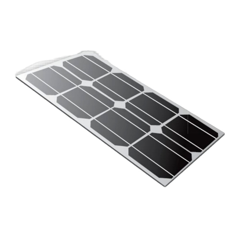
solarcentre GEO User manual

Connecting your Geo
solarcentreR
making solar that works
GEO
SOLAR KITSTM
Please read all instructions carefully before any installation work begins.
Please observe correct polarity at all times: Positive = Red; Negative = Black.
Positioning your Solar Panel
Position your solar panel, ideally on a sloping roof facing south, at an angle of 50 – 70 degrees
to the horizontal. If this is not possible, remote positioning may be required to give maximum
performance, although west or southwest will still provide good power generation. Avoid shaded
areas.
Step 1 Fitting the cable to the solar panel
1.1 Before fitting the cable to the solar panel, decide on the panel location and cut the
appropriate length of cable ensuring it will reach from the solar panel to the battery.
1.2 Remove the cover from the terminal box on the rear of the solar panel.
1.3 Loosen (do not remove) the two terminal screws
1.4 Take one end of the cable and strip back 4.5cm of the black outer sheath. Strip 1.5cm of the
insulation of the red and black inner cables to expose the bare conductor.
1.5 Feed the cable through the hole in the terminal box.
1.6 Twist the bare conductor ends tightly and wrap clockwise around the loosened terminal
screws. Alternatively two ring terminals (supplied) can be crimped onto the bare conductor
ends.
1.7 RED (Positive); BLACK (Negative)
1.8 As marked on the inside of the terminal box
1.9 Tighten terminal screws and place the terminal box cover.
Step 2 Mounting the solar panel
2.1 Drill an 8mm access hole, ideally positioned close to or underneath where the solar panel
will be located.
2.2 Fix the mounting blocks to the outer surface of the roof or wall.
2.3 Thread the cable ties through both loops on the mounting blocks
2.4 Insert the loose end of the cable from the solar panel into the access hole and lower the
panel onto the fixing surface, ensuring the pre-drilled holes on the back of the panel frame
line up with the mounting blocks.
Questions?
call 01727 841014
page 1

Connecting your Geo
solarcentreR
making solar that works
GEO
SOLAR KITSTM
2.5 Thread the pointed end of each cable tie through each panel frame hole and then through
the square end of the tie. Now pull the pointed end of the tie tight to lock off.
2.6 Cut off the loose end of the cable tie.
2.7The access hole can now be filled to prevent leakage with a suitable sealant or adhesive.
Step 3 Connecting solar panel to the system battery.
Geo 1 and Geo 2 solar panels can be connected direct to the battery using the cable supplied.
3.1 Strip back 20cm of the black outer sheath of the cable end to be connected to the battery.
3.2 Cut the red cable at the halfway point and strip 5mm of the red insulation from both the cut
ends. Twist the bare wire ends tightly . Fit into the screw terminals on each of the fuse holder
pieces.
3.3 For both Geo 1 and Geo 2, connect the cable to your battery. Strip red and black insulation
from the the inner cable. Twist the bare conductor ends tightly and wrap clockwise around the
loosened terminal screws. Alternatively two ring terminals (supplied) can be crimped on to the
bare conductor ends.
3.4 Do not connect the battery until the installation is complete.
Step 3A Connecting the Voltage Regulator
Geo 3 and Geo 4 require a voltage regulator to protect the battery from overcharging and to
ensure the panel does not discharge the battery at night.
3A.1 Position the Solar voltage regulator as close as possible to the battery (must be a dry
location)
3A.2 Measure the distance between your battery terminals and the Solar voltage regulator.
3A.3 Cut the measured distance from the end of the cable.
3A.4 Prepare as described in 3.1 and 3.2 the end of the cable from the inline connector (if fitted)
and attach to the two terminals on the Solar voltage regulator.
3A.5 Take one end of the remaining cable, prepare as above and attach to the centre terminals
on the Solar voltage regulator by using the same procedure as described in 1.6.
IMPORTANT - When using a voltage regulator, components need to be connected and discon-
nected in the right order for it to function properly. Connect battery to voltage regulator first and
then the panel to the voltage regulator and finally any products such as lighting or radios that
you would like to run from the voltage regulator. Please reverse this process when disconnect-
ing.
Questions?
call 01727 841014
page 2

Connecting your Geo
solarcentreR
making solar that works
GEO
SOLAR KITSTM
Step 4 Connect the cable to the wall switch and battery
Remove the knockout's at the top and bottom of the wall switch mounting box to allow cable
access and secure to the wall at the desired location. The wall switch (10Amp max) will control
and switch the light fittings. The main supply from the battery will run through the wall switch via
the inline fuse. The positive cable is the wire that must be switched, the Negative wire must
remain unbroken. It may be necessary to join the Negative wire with the single connector block
supplied in the switch housing to complete the circuit. Do not connect the battery until the instal-
lation is complete.
Connect Cable to Wall Switch
4.1 Measure and cut to length the cable that will run from the battery to the Wall Switch.
4.2 Remove 3.5cm of the outer black cable sheath.
4.3 Strip back approx 5mm of insulation from the red and black wires.
4.4 Feed cable into the bottom of the switch mounting box.
4.5 Connect the red wire to the bottom of the switch.
4.6 Connect the black wire to the single connector block supplied.
Connect Cable to Battery
4.7 Strip back 20cm of the black outer sheath of the cable end to be connected to the battery.
4.8 Repeat Step 3.2
4.9 Follow Step 3.3 and connect the cable ends to the same crocodile clips as the cable running
from the solar panel.
Do not connect the battery until the installation is complete.
Step 5 Measure and cut Cable to run from the Wall Switch to the Lamp Holder
5.1 Repeat steps 4.2 and 4.3
5.2 Feed cable into top of switch mounting box.
5.3 Connect the red wire to the top of the switch, marked TOP.
5.4 Repeat step 4.6
5.5 Secure the switch plate to the mounting box.
Questions?
call 01727 841014
page 3

Connecting your Geo
solarcentreR
making solar that works
GEO
SOLAR KITSTM
Step 6 Connecting the Lamp Holder
6.1 It will be necessary to remove or cut away a small portion of plastic at the lamp holder base
to allow cable entry
6.2 At the cable end to be connected to the lamp holder, remove 4cm of outer sheathing.
6.3 Repeat step 4.3
6.4 Connect with supplied connection block to existing fitted wire red to red, black to black.
6.5 Secure the Lamp Holder at the desired location.
6.6 Geo 2, 3 and 4 have more then one lamp holder to fit. Simply connect all subsequent lamp
holders to the first by connecting red to red and black to black (parallel connection)
Notes
a) If a battery capacity of less then 35Ah or 70Ah is to be used with Geo 1 and 2 respectively,
the solar panel must be disconnected from the battery during long periods of system inactivity
(e.g. When on holiday or in the summer etc.) or overcharging may occur and the battery could
be permanently damaged. Alternatively contact The Solar Centre who can supply a voltage
regulator (at a small extra charge).
b) We recommend the use of standard leisure (caravan) battery or auto battery. These can
typically be found in most car / caravan accessory stores and are typically 75Ah to 85Ah capac-
ity. If the battery location could cause a spillage from the battery then we would recommend
using a sealed deep cycle battery.
c) When routing cable and fittings, care must be taken that cables and fittings cannot become
damaged in the normal course of use by machinery or livestock. Care must be taken to protect
cables and fittings from damage from any external influence. Care must also be taken near any
gas supplies, as arcing from switches and appliances may be a hazard.
d) If an existing electrical installation is already in place or in service, the 12v DC Solar installa-
tion and sub circuits, including battery, must be kept totally separate and in no way integrated, or
made part of the original existing system. 12Volt DC and 240AC cables cannot be run in the
same conduits and trunking.
e) Run times may vary and will be dependent on weather conditions, the solar panel product
energy even in cloudy conditions, but winter production will be less primarily because of the
position of the sun in relation to the solar panel. Less power is produced when the sun is low in
the sky.
Questions?
call 01727 841014
page 4

Connecting your Geo
solarcentreR
making solar that works
GEO
SOLAR KITSTM
f) Increased run times can be achieved in spring/summer months when the sun is much higher
in the sky.
g) Normal battery maintenance applies: check fluid levels on a regular basis, top up as neces-
sary.
h) Extra cable can be purchased by the metre from The Solar Centre.
i) Many 12v accessories can be added: lighting, audio equipment, visual equipment, water
pumps etc. to make a more comprehensive installation.
j) All Geo Systems can be expanded to power more appliances by 'daisy chaining' more solar
panels to the original installation. Please contact The Solar Centre on
01727 841 014 for advice on your specific requirements.
k) (Recommended battery size 35 Ah to 85Ah) Site the battery in a well ventilated and dry area,
protected from frost. Always start with a fully charged battery. If the battery is flat at the time of
installation of the Geo Kit allow the fully connected system a period of between 8 to 14 days to
fully charge the battery before first use.
Questions?
call 01727 841014
page 5
Table of contents
Other solarcentre Inverter manuals
Popular Inverter manuals by other brands
aptos
aptos MAC 800R user manual
Briggs & Stratton
Briggs & Stratton 076000NG Service & troubleshooting guide

Generac Power Systems
Generac Power Systems quietpact 85d owner's manual
Cotek
Cotek SE350 series user manual

Briggs & Stratton
Briggs & Stratton 040395-00 Operator's manual

AEG
AEG Protect PV user manual


