Aetechron DSR 100-15 User manual

About the DSR 100-15 Dropout, Surge, Ripple Simulator and AC/DC Voltage Source
Congratulations on your purchase of a DSR 100-15 AE Techron dropout, surge, ripple simulator and AC/DC voltage
source. The DSR 100-15 provides a complete, single-box solution for immunity testing. It includes a simple-to-use yet
powerful standards waveform generator matched with an industry leading power supply technology and comes with an
extensive library of tests for many automotive and aviation standards.
The DSR 100-15 is 4-quadrant, allowing it to source and sink current. The DSR 100-15 has power in reserve; it provides
continuous DC power as rated, and is able to provide 4X rated power for in-rush testing up to 200 mS, as is required in
DO 160 Section 16.
The AE Techron brand is known throughout the world for its robust precision amplifiers and test systems as well as its
product service and support.
Disclaimer
Although AE Techron has made substantial effort to ensure the accuracy of the Standards' test files (SWG files), which
are included with the DSR 100-15, no warranty, expressed or implied, is made regarding accuracy, adequacy,
completeness, legality, reliability or usefulness of the information provided. It is the responsibility of the user to ensure the
accuracy and applicability of these test files for their intended purposes.

Getting Started
DSR 100-15 Setup
The following steps explain how to connect the DSR 100-15 using the cables and accessories provided.
Check Front-Panel Controls
A. Check to make sure that the AC power/breaker switch for both the Controller and the amplifier module are in the
ON (|) position.
B. Make sure the Gain control is turned to the 100 (cal) position (fully clockwise).
Connect Test Supply:
Make sure the DSR 100-15 system is turned off and AC power is disconnected. Using the supplied pin-plug
connectors and wiring appropriate for your application, connect fromt he DSR 100-15 front-panel positive and negative
test supply connectors to the device under test.
Back-Panel Connections:
A. Plug the USB keyboard into the USB port labeled KEYBOARD on the DSR 100-15 back panel.
B. Plug the USB mouse into the USB port labeled MOUSE on the DSR 100-15 back panel.
C. Plug the HDMI to DVI cable into the HDMI port labeled MONITOR on the DSR 100-15 back panel, and then
connect the cable to the DVI port on the monitor.
D. Plug the monitor power cord into the monitor, and then connect the cord to a power source.
E. Plug the DSR 100-15 power cord into the power connector located on the DSR 100-15 back panel, and
then connect the cord to a 20A power source.

F. OPTIONAL: To connect the DSR 100-15 to be accessed and controlled through a network: Plug the Ethernet
cable to the Ethernet port on the DSR 100-15 back panel labeled NETWORK, and then plug the Ethernet
cable into a router, switch or hub on the network. See the topic "DSR 100-15 via Network" for more
information.

Startup Procedure
Complete the following steps to power up a DSR 100-15 system:
A. Use the monitor's power switch (last button on the right) to turn on the monitor.
B. Depress the DSR 100-15 SYSTEM POWER switch to turn the DSR 100-15 ON.
C. Wait for the DSR 100-15 interface to load (loading will take up to 30 seconds). See additional topics in this Help
system for "System Calibration" and "Basic Operation."

System Calibration
IMPORTANT: Before operating the DSR 100-15, the Calibration Test should be run to determine the correct system
settings for the DSR 100-15.
The DSR 100-15's default System Gain setting is 20, and the default DC Offset setting is 0, but these settings should be
verified and adjusted, if needed, to reflect the measured gain of your DSR 100-15 system at the Test Supply outputs. If
you are measuring the output of the DSR 100-15 without amplification (from the Controller's front-panel BNC signal
output), a System Gain of 1 can be used for DSR 100-15 calibration (for an expected output of
10Vp/20Vpp).
Complete the following steps to run the calibration test and adjust the DSR 100-15's System Gain and DC Offset settings:
1. Select the Settings button and then open the System Calibration tab.
2. Make sure an estimated gain is entered in the Amplifier Gain input box. A default gain of 20 will be pre-entered in
this box.
3. Adjust the Calibration Test Voltage, if desired. A default test signal of 1 Vp will be pre-entered in this box. Note: the
default DC offset is 0 and cannot be changed.

4. Connect an oscilloscope to the DUT (load at the Test Supply output).
5. Press the Run Calibration Test button to begin the Calibration Test. The DSR 100-15 will generate a 1 kHz sine
wave signal at the test voltage entered in the Calibration Test Voltage box.

6. Note the output voltage and any DC offset shown on the oscilloscope. Enter these results in the Measured Output
and Measured DC Offset boxes on the System Calibration tab. The DSR 100-15 Controller will automatically
calculated the required Gain and DC Offset adjustments and display them on the Applied Gain Ajustment and
Applied DC Offset lines on the System Calibration tab.

7. Press the Save button to save the resulting calibration numbers and close the Settings window.


Basic Operation
IMPORTANT: Before operating the DSR 100-15 system, the System Calibration Procedures should be performed to
determine the correct System Gain and DC Offset settings for the DSR 100-15. See the "System Calibration" topic for
more information.
1. Select the Settings button and then open the System Calibration tab to set the DSR 100-15 system gain. The
default setting for a DSR 100-15 system is 20, but this should be calibrated to match your actual system gain. If
measuring DSR 100-15 Controller output directly (without amplification), the system gain can be set to 1 for a
10Vp/20Vpp output.
2. Use the Files button to load a test from the Standards library.

3. Use the Add Wave and Add Control buttons to select a waveform or control to add to the active test window.
4. Select the tab for a waveform or control to open the Properties dialog. Edit the properties to create complex
waveforms and waveform sequences.
5. Segments can be dragged to change their order. To remove a segment from the test, press the X on the segment's
tab.
6. When your test sequence is complete, press the Arrow button to begin generating signal output from the amplifier.

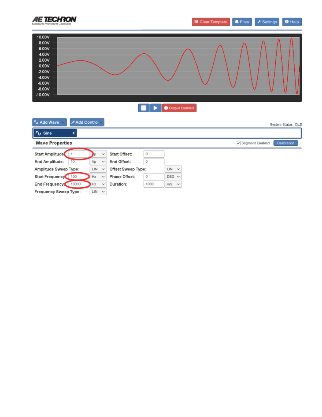
Adding Waveforms
The Add Wave button opens a drop down menu listing the types of waveforms that can be added to the active window.
You can choose Sine, Ripple, DC, Triangle, Square or Sawtooth waveforms.
When you choose a waveform from the Add Wave drop-down menu, the default waveform of that type is added to the
active window. Click on the tab or the waveform in the display to open the Properties form containing the available
property settings for that waveform. See the individual entries in this Help system for more information about the settings
available for each waveform type.
As you add or adjust settings for the waveform in the Properties tab, the visual depiction in the active test window will
adjust to reflect the approximate signal being described by the waveform properties. Note that time sequences are NOT to
scale.
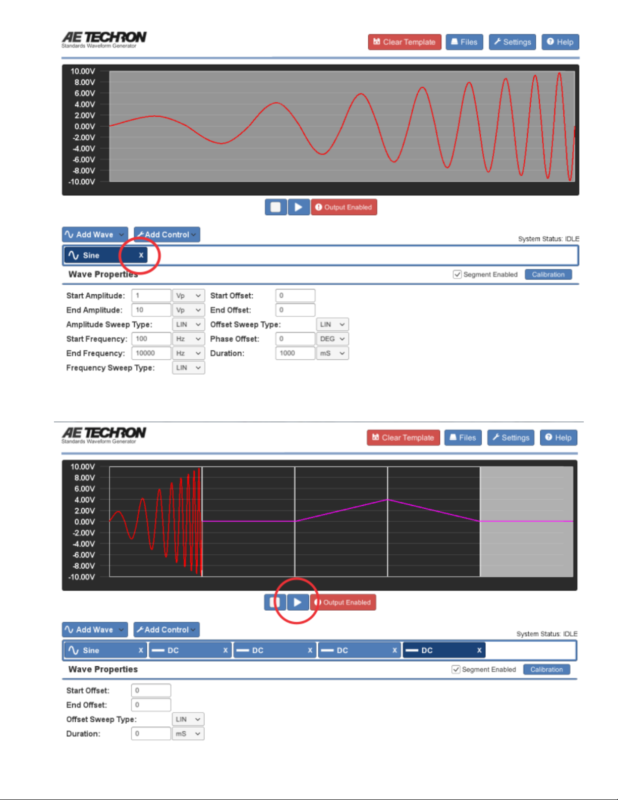
To add additional waveforms to the active test, select additional waveforms from the drop-down menu. New waveforms
will be added sequentially and will appear to the right of the selected control or waveform in the active window.

Position Waveforms: To reposition a waveform within the test sequence, click on the waveform to highlight and then
click and drag the waveform to the desired position in the sequence.
Enable/Disable Segment: Each waveform segment can be set to Enabled (Segment Enabled checkbox checked) or
Disabled (unchecked). When enabled, the waveform will be played as part of the test sequence. When unchecked, the
waveform will be skipped during the running of the test segment. This can be useful when building or troubleshooting test
sequences to skip over long or previously verified segments.
Segment Calibration: Each waveform segment can be individually calibrated using the segment calibration procedure.
This can allow minor adjustments in system gain to be performed for a single segment.
To perform segment level calibration, complete the following:
1. Locate the segment to be calibrated and press the blue Calibration button located to the right of the waveform
properties. The Segment Calibration window will open.
2. Connect an oscilloscope to the DUT (load at the amplifier output).
3. Press the Run Calibration Test button to begin the Calibration Test. The DSR 100-15 will continuously generate a
waveform with the amplitude and frequency defined in the wave properties.
4. Note the output voltage shown on the oscilloscope. If the output does not match the test voltage, enter the amount
required to adjust the output to match the test voltage in the Wave Gain input box. For example, if the oscilloscope
reading is 1.1 Vp, enter -0.1 in the Wave Gain input box. Rerun the Calibration Test to verify the calibration, and
then press the Close button to save your adjustment and close the Segment Calibration dialog.
NOTE:The calibration test can only produce voltage levels within the voltage limits of the system. If levels above system
limits are entered in the Wave Gain input box, the calibration test levels will remain at the highest level capable.

Adding Controls
The Add Control button opens a drop down menu listing the types of controls that can be added to the active window. You
can choose Trigger, Fixed Loop, Variable Loop, Template, or GPIO Output.
When you choose a control from the Add Control drop-down menu, an icon representing that control type is added to the
active window, and a form containing the available settings for that control opens below the active test display. See the
individual entries in this Help system for more information about the settings available for each control type.
To add additional controls to the active test, select additional controls from the drop-down menu. New controls will be
added sequentially and will appear to the right of the selected waveform or control in the active window. To reposition a
control within the test sequence, click on the control to highlight and then click and drag the control to the desired position
in the sequence.

Running a Test
One or more waveforms and/or controls that have been added to the active test window can be run using the controls located
below the active window.
RUN: When the Run button is pressed, the active test sequence will be sent to the DSR 100-15, and the system will
begin generating signal starting at the beginning of the test sequence (the waveform or control farthest to the left). The
System Status reporting message will change from 'Idle' to '1 of X,' with X being the total combined number of waveforms
and controls in the test.
An individual segment may be highlighted in the active test window during playback. This occurs when the DSR 100-15
system is currently generating the highlighted segment and the segment is equal to or greater than one second in duration.
Segments shorter than one second are too short to register as being highlighted.
STOP: When the Stop button is pressed, the DSR 100-15 will stop signal generation, and the test will reset to the start of
the first waveform. The system will report its status as 'Idle.' The system will also report its status as Idle at all times that the
DSR 100-15 is operating normally but a test is not active .
OUTPUT ENABLED/DISABLED: When the Output Enabled button is displayed, the signal defined by the
active test sequence will be generated by the DSR 100-15. When pressed, the Output Enabled button will toggle to the
Output Disabled display , and the test sequence can be run without generating output signal. This can be

useful for testing a sequence before generating output.

Controlling the DSR 100-15 Through a Network
To access and control the DSR 100-15 through your local network, complete the steps below:
A. Connect the DSR 100-15 to the keyboard, monitor, mouse and amplifier as directed for a free-standing workstation setup
(see the topic "Getting Started"), but also connect the Ethernet cable between the DSR 100-15r and your network hub,
router or switch, as shown below:
B. Power up the DSR 100-15 system, and wait for the Controller interface to load (this can take up to 30 seconds). Press
the Settings button to open the Settings window, and then select the About Server tab. Write down the IP address shown
in the IP Address section for later reference, and then press the Cancel button to close the Settings window. NOTE: If
the Service Endpoint box is blank or contains the IP address 0.0.0.0, then the DSR 100-15 is not connected to your
network. Check your Ethernet connection or contact your network administrator for assistance.

C. Insert the microSD card with USB adapter (included with the DSR 100-15) into an open USB port on the computer to be
used for accessing the DSR 100-15 across the network. Open the USB drive and then locate and install and the SWG
Setup.exe file.
D. When the program has loaded, the notice "Not Connected to DSR - Running in Demo Mode (Click to Connect)" will be
displayed in the upper left of the window. Click the message to open the connection dialog, and then type the DSR 100-
15's IP address you wrote down into the IP Address text box. Press OK to connect to the remote DSR 100-15. The DSR
100-15's interface will be displayed on your computer monitor, and the DSR 100-15 system can now be controlled
remotely.
Table of contents
Other Aetechron Inverter manuals

Popular Inverter manuals by other brands

Ingecon
Ingecon SUN STORAGE 100TL Use and Settings

tbs electronics
tbs electronics powersine 200-12 owner's manual

Schumacher
Schumacher PI-100SL owner's manual

Kaco
Kaco blueplanet 87.0 TL3 manual

Victron Energie
Victron Energie Phoenix Combi 12/1000/50 user manual

Generac Power Systems
Generac Power Systems 04673-2 Installation and owner's manual


Amerec
Amerec Steambath Generator 3K10 owner's manual

KB Electronics
KB Electronics KBMD-240D Installation and operating instructions

TSUNESS
TSUNESS TSOL-A3.0K-H user manual

MY PROJECT
MY PROJECT MPSW 300 C3 instructions

Lennox
Lennox e-Lite LV-M080 Series Installation and operation manual

Sungrow
Sungrow SG50KTL-M-20 Quick installation guide