Atlas IED WTSD-MIX31K User manual

– 1 –
AtlasIED.com
TELEPHONE: (800) 876-3333
SUPPORT@ATLASIED.COM
1601 JACK MCKAY BLVD.
ENNIS, TEXAS 75119 U.S.A.
WTSD-MIX31K
3x1 Mic / Line / BT / AUX Mixer
with Optional Dante®Audio
Network Interface

– 2 –
WTSD-MIX31K
Owner’s Manual
AtlasIED.com
TELEPHONE: (800) 876-3333
SUPPORT@ATLASIED.COM
1601 JACK MCKAY BLVD.
ENNIS, TEXAS 75119 U.S.A.
Table of Contents
Introduction ........................................................................................................... 3
Key Features.......................................................................................................... 4
Applications ........................................................................................................... 4
Package Contents.................................................................................................. 4
WTSD-MIX31K Component Interface ................................................................... 5
Front Panel Description ......................................................................................... 6
Rear Panel Description .......................................................................................... 9
WTSD BUS Structure .......................................................................................... 10
WTSD-PWBOB Features......................................................................................11
Using Commercial Grade Bluetooth.................................................................... 13
Sleep Mode Feature............................................................................................ 15
Things To Consider Before Installation ................................................................ 16
Things To Be Careful Of During Installation......................................................... 16
Choosing A WTSD Wall Mounting Method ......................................................... 17
Electrical Boxes and Rings .................................................................................. 18
Installing the Power Supply................................................................................. 20
Installing the WTSD Indoors................................................................................ 20
Installing the WTSD Outdoors............................................................................. 20
Using the Optional WTSD-COVER Accessory..................................................... 21
Installing Multiple WTSD Mixers On the Same BUS .......................................... 22
Using the WTSD-PWHUB Accessory.................................................................. 23
Connecting to WTSD To a Dante®Network ........................................................ 23
WTSD Product Family ......................................................................................... 24
Optional Accessories........................................................................................... 24
Specifications ...................................................................................................... 25
Block Diagram ..................................................................................................... 29
Dimensional Drawings ........................................................................................ 30
FCC Warning........................................................................................................ 31
Warranty .............................................................................................................. 32

– 3 –
WTSD-MIX31K
Owner’s Manual
AtlasIED.com
TELEPHONE: (800) 876-3333
SUPPORT@ATLASIED.COM
1601 JACK MCKAY BLVD.
ENNIS, TEXAS 75119 U.S.A.
Introduction
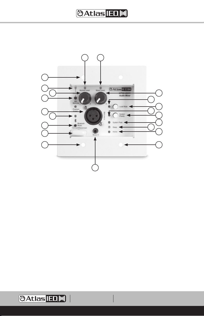
Model WTSD-MIX31 is a 3x1 Mic / Line / Aux / Bluetooth analog mixer that features a
balanced microphone / line input and an auxiliary 3.5mm and Bluetooth summed input
with a balanced line output. The WTSD-MIX31 utilizes commercial grade Bluetooth
technology featuring ultra low noise levels, long range connectivity, no auto connect and
quick disconnect bump feature. Selection between mic or line level for the XLR input is
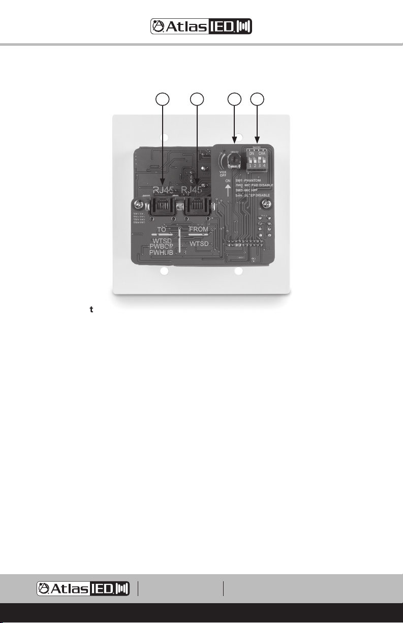
done via front panel switch. The high gain mic inputs incorporate user enabled Phantom
Power for condenser microphones and a 125Hz low cut filter to eliminate unwanted low
frequency interferences. A local mute button mutes output to the bus and a system
priority button can mute building wide BGM systems to isolate the room. An adjustable
VOX feature allows for AUX input background audio to be muted when announcing is
present. The AUX input is a stereo 3.5mm jack and is electronically summed to achieve
the best audio performance. Separate level controls for each input provide control for the
audio mix needed.
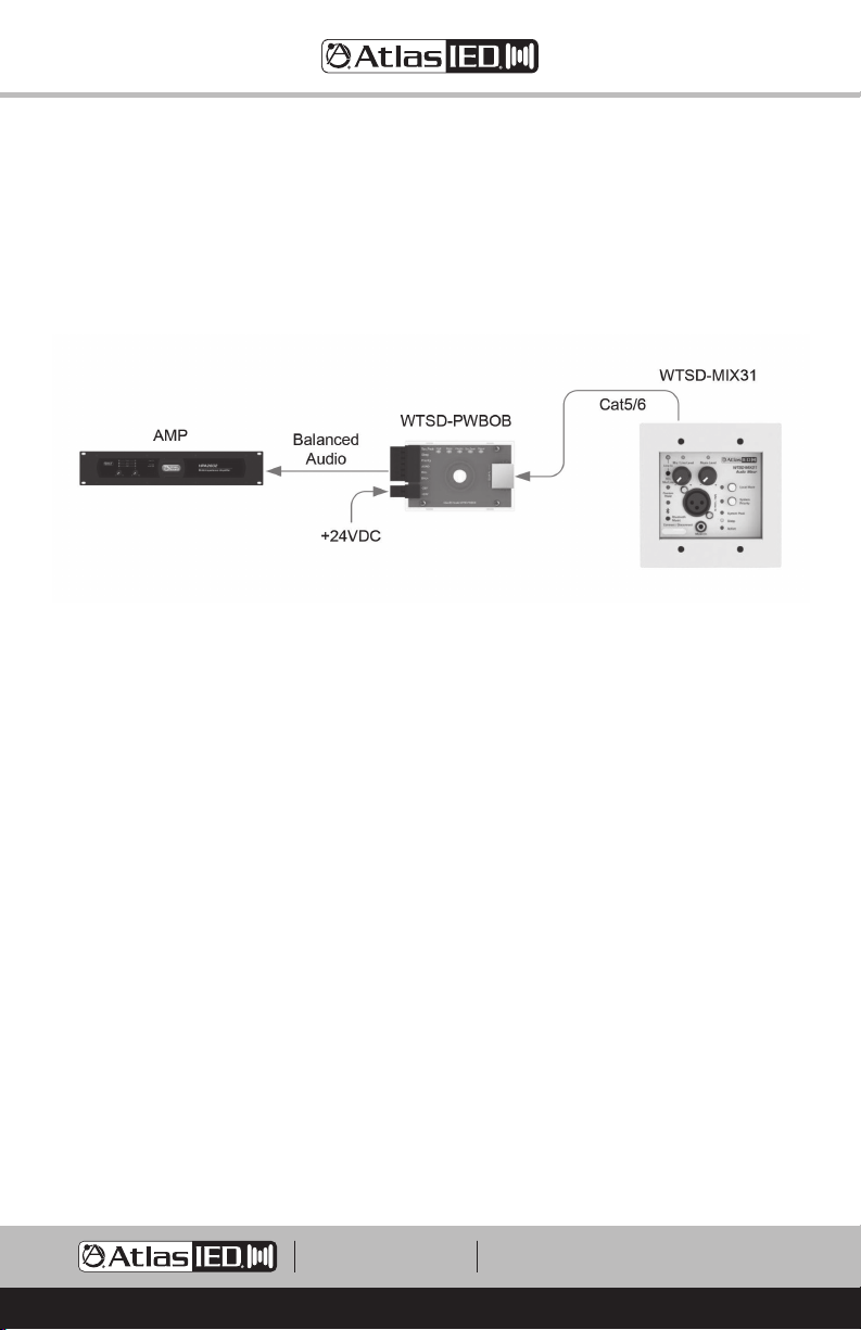
A basic WTSD system consists of four elements; a WTSD mixer, Cat5/6 cable, inline 24V
DC power supply and an end point break out board / hub. All four are included with the
purchase of a WTSD mixer except for the Cat5/6 cable. A 2-gang box is all that is needed
to complete an installation. There are two versions of the WTSD end points offered. The
WTSD-PWBOB comes with each unit and features a balanced audio output with signal,
mute, system priority and power LEDs and 12V DC logic output for remote system muting
or power sequencing. The WTSD-PWHUB is sold separately and features level control
at the system head end, input limiting, isolated relay outputs to trigger system priority
muting or system power activation, and an emergency mute port. The WTSD features an
energy saving auto sleep function that can shut off the audio system when not in use
after approximately 1 hour. As soon as the WTSD mixer senses an audio signal, the WTSD
sends a command down the bus to wake the system up.
The WTSD-MIX31 analog audio BUS can easily be converted to an Audinate Dante®digital
signal by interfacing with the optional AtlasIED TSD-DAC2i converter. The WTSDs are
uniquely designed to fit into most 2-gang electrical boxes and utilize industry standard
Cat5/6 cable for power, control, and audio. The WTSDs deliver high quality audio hundreds
of feet by the use of a low noise / high gain preamp design and balanced audio bus. The
proprietary low voltage bus is designed so that up to 3 WTSD mixers can be daisy chained
on the same bus cable run while allowing for independent mixer operation. Each WTSD
incorporates separate level controls for each input, a local mute, system priority override
and an auto sleep function.
The optional WTSD-COVER stainless steel weather resistant locking security cover with
gaskets is available for tamper proof indoor or outdoor applications. The PCBs are weather
treated to reduce corrosion in damp environments. With the PCB treatment and the
WTSD-COVER accessory, the installation will have protection against the environment and
tamper protection for years of continuous operation.

– 4 –
WTSD-MIX31K
Owner’s Manual
AtlasIED.com
TELEPHONE: (800) 876-3333
SUPPORT@ATLASIED.COM
1601 JACK MCKAY BLVD.
ENNIS, TEXAS 75119 U.S.A.
Key Features
• Indoor or Outdoor Use
• XLR Balanced Mic or Line Input with Level Control
• 3.5mm Stereo Actively Summed Input with Level Control
• Commercial Grade Bluetooth Input with Level Control
• Wall Plate Mounted, Fits Into Most 2-Gang Boxes
• Uses Industry Standard Cat5/6 Wire
• DC Bus with Peak Indicator
• High Gain Balanced Line Output for Long Distance Applications Up to 400ft
• 125Hz /12dB Low Cut Filter for Mic / Line
• Local Mute or VOX Mute
• Remote Trigger Output for Remote Amplifier Turn On
• System Priority Mute Function
• Input Signal & Peak Indicators
• Energy Saving Auto Sleep Mode
• Pairing Connect / Disconnect Switch
• WTSD-COVER Water Resistant Stainless Steel Locking Cover (Optional)
• WTSD-PWHUB Receiver with Limiter and Isolated Relays & Emergency Mute (Optional)
• TSD-DAC2i Analog to Dante®Digital Audio Transmitter (Optional)
Applications
• Indoor / Outdoor Sports Complexes
• Schools - Gymnasiums, Rally Areas
• Hotel Ballrooms
• Community Multi-use Facilities
• Industrial Facilities
Package Contents
• WTSD-MIX31, Qty 1
• WTSD-PWBOB, Qty 1
• Inline Power Supply 24VDC 1A, Qty 1
• 6/32 x 1" Pan Head Screws, Qty 4
• RJ45 Shims, Qty 4
• Manual, Qty 1

– 5 –
WTSD-MIX31K
Owner’s Manual
AtlasIED.com
TELEPHONE: (800) 876-3333
SUPPORT@ATLASIED.COM
1601 JACK MCKAY BLVD.
ENNIS, TEXAS 75119 U.S.A.
WTSD-MIX31K Component Interface
The WTSD-MIX31 connects to the WTSD-PWBOB via Cat5/6 cable. The 24VDC 1A power
supply connects to the WTSD-PWBOB. The WTSD-PWBOB connects to the amplifier.
Note: The max cable distance from WTSD-PWBOB to WTSD-MIX31 is 400ft. The Cat5/6
cable is not included.

– 6 –
WTSD-MIX31K
Owner’s Manual
AtlasIED.com
TELEPHONE: (800) 876-3333
SUPPORT@ATLASIED.COM
1601 JACK MCKAY BLVD.
ENNIS, TEXAS 75119 U.S.A.
Front Panel
1. Mounting Holes
Fits a 2-gang NEMA electrical box.
2. Active / Power Indicator
Illuminates blue when 24VDC is present.
3. Sleep Indicator
Illuminates yellow when no audio signal is sensed at the WTSD after 1 hour. Note: Each
WTSD sleep indicator operates independently. Refer to Sleep Mode Feature section for
details.
4. Mic / Line Input
Connects to balanced line or mic level sources via the XLR connection. For mic or line
input gain selection, press the Mic / Line mode switch. When the line-in indicator is
illuminating green the input will accept line level signals. Note: Unbalanced line inputs
can be inserted with proper wire configuration by connecting the Pin 1 (G) and Pin 3 (–)
terminals together.
5. Mic / Line Mode Switch
For mic or line input gain selection, press the Mic / Line mode switch. When the line-in
indicator is illuminating green the input will accept line level signals.
1
5
6
7
11
3
15
17
1
4
10
19 2
14
16
18
1
12
8 13
9

– 7 –
WTSD-MIX31K
Owner’s Manual
AtlasIED.com
TELEPHONE: (800) 876-3333
SUPPORT@ATLASIED.COM
1601 JACK MCKAY BLVD.
ENNIS, TEXAS 75119 U.S.A.
6. Line Mode Indicator
When the line-in indicator is illuminating green the XLR input is in line mode.
7. Mic / Line Level
Adjust the level Mic / Line input signals. Turn clockwise to increase the signal level and
counter-clockwise to decrease it.
8. Mic / Line Input Signal Indicator
Illuminates green when the input signal strength reaches 25mV to verify a signal path.
Note: The LED will not illuminate if the input level is turned Off / fully counter-clockwise.
9. Music Input 3.5mm
Electronically sums unbalanced audio signals through stereo 3.5mm input connector. The
music level control is on the front panel. This input can be muted via the VOX adjustment
pot for priority paging applications. Note: The 3.5mm input will take priority over the
Bluetooth signal.
10. Bluetooth Music Connect / Disconnect Switch
Use this switch to pair a device, connect to a device or disconnect a device. Refer to the
Using Bluetooth Section for detailed usage information.
11. Bluetooth Status Indicator
This blue indicator has different modes to indicate the status of the Bluetooth connectivity.
Refer to the Using Bluetooth Section for detailed usage information.
12. Music Level
Adjust the level 3.5mm / Bluetooth input signals. Turn clockwise to increase the signal
level and counter-clockwise to decrease it.
13. Music Input Signal Indicator
Illuminates green when the input signal strength reaches 25mV to verify a signal path.
Note: The LED will not illuminate if the input level is turned Off / fully counter-clockwise.
14. Local Mute Switch
When the local mute switch is pressed, all local input signals will be muted and the local
mute indicator will illuminate red.
15. Local Mute Indicator
Illuminates red when the local mute switch is pressed. All local inputs signals will be
muted.
16. System Priority Switch
When the system priority switch is pressed, the system priority circuit is activated and
sends a command to the WTSD-PWBOB. The system priority port on the WTSD-PWBOB
will have 10V DC present to trigger a command on an external product such as muting or
turning an amplifier or power strip On or Off. Note: A relay is activated when using the
WTSD-PWHUB instead of the WTSD-PWBOB. Refer to the WTSD-PWHUB features for
more details.

– 8 –
WTSD-MIX31K
Owner’s Manual
AtlasIED.com
TELEPHONE: (800) 876-3333
SUPPORT@ATLASIED.COM
1601 JACK MCKAY BLVD.
ENNIS, TEXAS 75119 U.S.A.
Front Panel
17. System Priority Indicator
Illuminates red when the system priority switch is pressed.
18. System Peak Indicator
Illuminates red when the input signal reaches 3dBV below when signal clipping will occur.
Occasional flashing is normal but if this indicator is continuously on, then reduce the input
level using the input level control on the front panel.
19. Bluetooth Antenna Cover
This cover protects the Bluetooth antenna. Do not push on this cover or damage may
occur.

– 9 –
WTSD-MIX31K
Owner’s Manual
AtlasIED.com
TELEPHONE: (800) 876-3333
SUPPORT@ATLASIED.COM
1601 JACK MCKAY BLVD.
ENNIS, TEXAS 75119 U.S.A.
Rear Panel
1. RJ45 Input
“To WTSD, PWBOB, PWHUB” – Connect the Cat5/6 cable between the WTSD being
installed and a WTSD-PWBOB or WTSD-PWHUB. If there is more than one WTSD in the
same BUS loop, this port connects to the second WTSD “From” RJ45 port.
2. RJ45 Output
“From WTSD” – This port should only be connected to a second WTSD port label “To
WTSD”.
3. Configuration Switch
• DIP Switch 1 - Phantom - 24VDC Phantom Power applies power for condenser mic
operation to Mic input terminal. Up position is On.
• DIP Switch 2 - Mic PAD Disable - When in the up position the mic gain setting will be
the most sensitive. When the switch is in the down position, the 10dB pad is engaged.
• DIP Switch 3 - Mic HPF - Low Cut filter engages at 125Hz with a roll off rate of 12dB
per octave on the Mic / Line input. This filter operates either in the Line or Mic mode
and is available on input 1. Ideal for vocal microphones to reduce low frequency energy
and to increase intelligibility. Up position is on.
• DIP Switch 4 - Sleep Disable - When in the up position the sleep mode will not be
engaged. When in the down position and no audio is present for 1 hour, sleep mode
will be activated.
4. VOX Adjustment Potentiometer
Adjusts the sensitivity of the mute circuit for priority paging messages. Set fully
counter-clockwise to turn this function Off. Turn clockwise to increase the sensitivity of the
audio signal to trigger the music signal mute function.
1 2 34

– 10 –
WTSD-MIX31K
Owner’s Manual
AtlasIED.com
TELEPHONE: (800) 876-3333
SUPPORT@ATLASIED.COM
1601 JACK MCKAY BLVD.
ENNIS, TEXAS 75119 U.S.A.
WTSD BUS Structure
RJ45
P8P8
P4P4
P5P5
P1
P2
P3
P7P7
P6P6
P8
P4
P5
P1
P2
P3
P7
P6
P8P8
P4P4
P5P5
P1
P2
P3
P7P7
P6P6
P8
P4
P5
P1
P2
P3
P7
P6
P8P8
P4P4
P5P5
P1
P2
P3
P7P7
P6P6
P8
P4
P5
P1
P2
P3
P7
P6
P8P8
P4P4
P5P5
P1
P2
P3
P7P7
P6P6
P8
P4
P5
P1
P2
P3
P7
P6
++
++
++
++
++
++
++
++
++
++
RJ45
WTSD-MIX31 or MIX41
CAT5/6
Non-shielded
WTSD CAT5/6 BUS STRUCTURE
BALANCED
AUDIO IN/OUT
BUFFER
BALANCED AUDIO BUS +
BALANCED AUDIO BUS -
BALANCED AUDIO BUS GND
POWER SUPPLY +V
POWER SUPPLY GND
SYSTEM PRIORITY-VOX BUS
AUTO SLEEP BUS
SYSTEM PEAK BUS
WTSD
PWBOB
PWHUB
TO
_______
WTSD
PWBOB
PWHUB
TO
_______ FROM
WTSD
RJ45
WTSD
PWBOB
PWHUB
TO
_______
WTSD
PWBOB
PWHUB
TO
_______
RJ45
WTSD-PWBOB
or PWHUB
WTSD-MIX31
or MIX41

– 11 –
WTSD-MIX31K
Owner’s Manual
AtlasIED.com
TELEPHONE: (800) 876-3333
SUPPORT@ATLASIED.COM
1601 JACK MCKAY BLVD.
ENNIS, TEXAS 75119 U.S.A.
WTSD-PWBOB Features
The power break out box (PWBOB) is a DC power injector / trigger control / audio interface
module. Each WTSD kit comes with a WTSD-PWBOB. This module can be placed in an
equipment rack and connected to a WTSD via Cat5/6 cable. The PWBOB serves as the DC
power injector to power WTSDs. The PWBOB is also the audio interface between a power
amplifier, DSP or mixer. The indicators on the PWBOB are a useful visual guide to see the
status of a WTSD that may be located several hundred feet away from the PWBOB in the
equipment rack.
1. Power Supply Input
Connect 24V DC Input. Note: Pay attention to supply + & – polarity. The 24VDC 1A power
supply that comes with the kit will have the 2-position connector installed on the wires.
2. PWR Indicator
This power indicator will illuminate green when 24V DC power is present at the Power
Supply input.
3. RJ45 to WTSD Interface
Connect a Cat5/6 cable to a WTSD RJ45 input marked “TO WTSD – PWBOB, PWHUB”
4. Balanced Audio Output
This 3-position port provides a balanced audio output to connect to an audio mixer or
amplifier input. Follow the wiring information for system interface. For unbalanced signals
connect the (GND) and the (–) terminals together. A removable 3-position 3.5mm pitch
Euro / Phoenix connector is supplied.
5. SYS Peak Logic Port
This logic port will provide a minimum of +1VDC when any of the WTSD audio input
signals are too high and the system peak LED is illuminated. Connect this port to an
external VCA limiter for additional system protection.
1
4
5
7
6
3
12
2 8 9 1110

– 12 –
WTSD-MIX31K
Owner’s Manual
AtlasIED.com
TELEPHONE: (800) 876-3333
SUPPORT@ATLASIED.COM
1601 JACK MCKAY BLVD.
ENNIS, TEXAS 75119 U.S.A.
6. Sleep Mode Logic Port
When the WTSD does not sense audio after 60 minutes, the WTSD panel and
WTSD-PWBOB sleep LED illuminate and this port logic voltage goes from 0V to +22VDC
(use power supply -24VDC (GND). This can be used to power On / Off an amplifier that
is equipped with remote turn such as AtlasIED HPA amplifiers or to trigger an AC Mains
power strip / sequencer On / Off like the AtlasIED AP-S20RT, AP-ECS3 or AP-ECS204. The
+22VDC low current logic voltage allows the sleep mode feature to interface with a wider
range of products that have remote turn on capability. This output current is limited to
2mA, protecting any equipment remote turn on interface. If the logic voltage is too high,
AtlasIED recommends using the WTSD-PWHUB. Note: Most products list a minimum
threshold voltage and current required to turn the product On / Off.
7. Priority Logic Port
When a WTSD system priority switch is pressed On, the system priority circuit is
activated and sends a command to the system priority logic port on the PWBOB. A 12V
DC logic will be present to trigger an external product action item such as muting an audio
background system or to turn an amplifier or AC mains power strip On / Off.
8. Sleep Mode Indicator
Illuminates green when no audio signal is sensed at the WTSD after 1 hour. Note: Refer to
the sleep mode feature section for feature details.
9. Priority Indicator
When a WTSD system priority switch is pressed On, the system priority circuit is activated
and sends a command to the WTSD-PWBOB to the LED to illuminate green.
10. SYS Peak Indicator
This indicator illuminates red when WTSD audio input signals are too high triggering the
system peak LED.
11. Signal Indicator
This indicator illuminates green when a WTSD input has audio present.
12. Mounting Hole
This mounting hole accepts a 1/4" bolt to mount to an equipment rack DIN rail.

– 13 –
WTSD-MIX31K
Owner’s Manual
AtlasIED.com
TELEPHONE: (800) 876-3333
SUPPORT@ATLASIED.COM
1601 JACK MCKAY BLVD.
ENNIS, TEXAS 75119 U.S.A.
Using Commercial Grade Bluetooth
The WTSD-MIX31 utilizes a commercial grade Bluetooth technology featuring
ultra-low noise digital interference, high gain output, non-auto connectivity and a local
disconnect bump feature. These features are not found in a consumer Bluetooth device. In
commercial applications speakers that are commonly used are designed to deliver a high
sound levels (SPL). These speakers are designed to be very efficient and are sensitive to
unwanted noise from the amplifier or audio source. Bluetooth technology was intended
for consumer applications and can produce unwanted digital noise at high volume levels.
The WTSD-MIX31 was designed to reduce or eliminate the digital noise issue. Another
common issue using consumer grade Bluetooth is the auto connect feature commonly
used. Auto connect is ok when getting in and out of a vehicle, but in a commercial
application it is not good to have someone walk into a room such as a gym and auto
connect giving them unauthorized control over the audio system. Another common issue
with consumer Bluetooth technology is when someone is unknowingly connected to
the audio system and no one else can take control over the audio system because it is
connected / locked to a person in the room. The WTSD-MIX31 does not utilize
auto-connect technology and has the ability to bump a paired device from its connection
by pressing the Bluetooth music disconnect switch. These features combined make the
WTSD-MIX31 ideal for commercial applications.
1. First Time Pairing
• Turn the music level control all the way down (fully counter-clockwise).
• Press the Bluetooth music connect / disconnect switch 1 time. The Bluetooth LED will
begin to blink blue.
• Go to the Bluetooth setting on the audio device being paired.
• Find “Atlas MIX31” and select pair.
• Once paired the Bluetooth LED will turn to steady state illumination, indicating the
device and the WTSD-MIX31 are now connected.
• Before playing music, adjust the audio device level to 3/4of the max source level.
Slowly turn the music level control to the desired listening level.
• If the device fails to connect in 30 seconds the Bluetooth LED will turn Off and restart
the pairing process.
2. Disconnecting the WTSD-MIX31 from the Paired Audio Source
• Press the Bluetooth music disconnect switch on the WTSD-MIX31.
• Turn Off the Bluetooth feature on the paired audio device.
• When disconnected the Bluetooth LED will not be illuminated.

– 14 –
WTSD-MIX31K
Owner’s Manual
AtlasIED.com
TELEPHONE: (800) 876-3333
SUPPORT@ATLASIED.COM
1601 JACK MCKAY BLVD.
ENNIS, TEXAS 75119 U.S.A.
3. Reconnecting an Audio Source
• Turn the music level control all the way down (fully counter-clockwise).
• Press the Bluetooth music connect switch 1 time.
• The Bluetooth LED will blink. Select “Atlas MIX31” in the Bluetooth device settings.
• The Bluetooth LED will illuminate a steady state indicating the device and the
WTSD-MIX31 are connected.
• Before playing music, adjust the audio device level to 3/4of the max source level.
Slowly turn the music level control to the desired listening level.
4. Out of Range Auto Connect
The WTSD-MIX31 has great range when compared to other Bluetooth devices due to the
antenna placement within the device. Achievable range for Bluetooth connection is 100ft
(33m) line of site. If the paired device goes out of the Bluetooth connection range from
the WTSD-MIX31 the following will happen:
• Intermittent music indicates the user needs to move closer to the WTSD-MIX31.
• If the user walks completely out of range, the WTSD-MIX31 will remain paired to the
last device for 1 minute looking to reconnect. After 30 seconds of searching, the
Bluetooth indicator will blink indicating it is about to be disconnected from the audio
source.
• After 1 minute, the Bluetooth LED will stop illuminating indicating the audio source was
disconnected. The Bluetooth connect switch will need to be pressed to re-connect.

– 15 –
WTSD-MIX31K
Owner’s Manual
AtlasIED.com
TELEPHONE: (800) 876-3333
SUPPORT@ATLASIED.COM
1601 JACK MCKAY BLVD.
ENNIS, TEXAS 75119 U.S.A.
Sleep Mode Feature
The WTSD family features an energy saving green mode of operation called Sleep Mode.
Sleep mode is activated when a WTSD does not sense any audio present after 60
minutes. After 60 minutes of no audio present the following happens:
1. One WTSD with a WTSD-PWBOB
A. The WTSD panel sleep LED illuminates yellow.
B. WTSD audio output is muted, not the BUS.
C. The PWBOB sleep LED illuminates green.
D. The PWBOB sleep port logic goes from 0V – 22V. This can be used to power
amplifiers On / Off that are equipped with remote turn such as AtlasIED HPA
amplifiers or to trigger an AC Mains power strip / sequencer On / Off like the
AtlasIED AP-S20RT, AP-ECS3 or AP-ECS204. The 22VDC low current logic
voltage allows for the sleep mode feature to interface with a wider range of
products that have remote turn on capability. This output current is limited to 2mA,
protecting any equipment remote turn on interface. If the logic voltage is too high,
AtlasIED recommends using the WTSD-PWHUB. Note: Most products list a
minimum threshold voltage and current required to turn the product On / Off.
2. Two or three WTSDs with a WTSD-PWBOB and one WTSD receives audio and wakes
up.
A. All WTSD panel sleep indicators illuminate yellow.
B. One of the WTSDs receives audio and wakes up from sleep mode and the sleep
indicator turns Off. The other WSTD sleep indicator(s) remains yellow.
C. The woke WTSD audio output is unmuted passing audio onto the BUS. The
other WTSD(s) remains locally muted.
D. The WTSD-PWBOB sleep LED is not illuminated.
E. The WTSD-PWBOB sleep port logic goes from 22V – 0V. This voltage can be used
to unmute an audio system or to turn On any equipment such as amplifiers or
power strips.
3. One WTSD with a WTSD-PWHUB
A. The WTSD panel sleep LED illuminates yellow.
B. WTSD audio output is muted, not the BUS.
C. The WTSD-PWHUB sleep LED illuminates yellow.
D. The PWHUB auto sleep port relay is engaged and goes from Normally Closed
(NC) to Normally Open (NO) contact position. This contact closure can be used to
mute an audio system or to turn Off any equipment such as amplifiers or power
strips to help conserve energy.

– 16 –
WTSD-MIX31K
Owner’s Manual
AtlasIED.com
TELEPHONE: (800) 876-3333
SUPPORT@ATLASIED.COM
1601 JACK MCKAY BLVD.
ENNIS, TEXAS 75119 U.S.A.
4. Two or Three WTSDs with a WTSD-PWHUB and one WTSD receives audio and wakes
up.
A. All WTSD panel sleep indicators illuminate yellow.
B. One of the WTSDs receives audio and wakes up from sleep mode and the sleep
indicator turns Off. The other WSTD Sleep indicator(s) remains yellow.
C. The woke WTSD audio output is unmuted passing audio onto the BUS. The other
WTSD(s) remains locally muted.
D. The WTSD-PWHUB sleep LED is not illuminated.
E. The WTSD-PWHUB auto sleep port relay goes from Normally Open (NO) to
Normally Close (NC) contact position. This voltage can be used to unmute an audio
system or to turn On any equipment such as amplifiers or power strips.
Things to Consider Before Installation
1. Select the correct mounting method. It is critical to fit the WTSD and the wires in
the box without causing damage to the WTSD. Refer to the section “Choosing a WTSD
Wall Mounting Method” for details on selecting the correct mounting method for the
application.
2. Check for local electrical codes for low voltage installation requirements.
3. Do not use shielded Cat5/6 cable. The RJ45 connectors on the WTSD do not have a
ground connection for the shield, so it is not necessary. The STP Cat6 can also be less
flexible when installing in a back-box.
4. If using a WTSD outdoors, make sure the optional WTSD-COVER is used and do not
expose directly to rain or snow. At minimum, place under an eve.
Things to Be Careful of During Installation
1. If using a shallow electrical back-box do not stuff the cables if there is no room. This
can damage the WTSD.
2. When running the Cat5/6 cable use standard IT wiring practices. If not, noise
interference can happen.
3. Avoid AC mains power. Never run the WTSD BUS cable parallel next to AC 120V – 240V
electrical runs and stay clear of AC outlets, or unwanted noise pick up can occur.
4. Using low grade / cost RJ45 connectors can cause an intermittent connection and
popping in the audio system may occur.

– 17 –
WTSD-MIX31K
Owner’s Manual
AtlasIED.com
TELEPHONE: (800) 876-3333
SUPPORT@ATLASIED.COM
1601 JACK MCKAY BLVD.
ENNIS, TEXAS 75119 U.S.A.
Choosing a WTSD Wall Mounting Method
When selecting the correct installation method of a WTSD it is important to know the
state / city electrical codes. The WTSD should not be required to be mounted a in a UL
certified electrical box. This is because the WTSD family meet lows voltage electrical
codes. AtlasIED suggests following IT wiring practices. Check for local electrical codes
and requirements before starting installation. Note: It is not advisable to bundle IT-Data
infrastructure wiring runs with the WTSD-BUS long runs.
All WTSDs are designed to mount using standard 2-gang (NEMA) size hole spacing and
fasteners. Fasteners are included with the WTSDs along with a WTSD-PWBOB and a
24VDC-PSU. If only one WTSD-MIX31 or WTSD-MIX41 is used in a system, then only one
Cat5 or 6-RJ45 to RJ45 (T568 non-crossover cable), will be needed to connect the WTSD
to the WTSD-PWBOB at the head-end. If other WTSDs are needed in the same system,
then a loop thru or 2 x Cat5 or 6 (one IN and one OUT) will be the max amount of wiring
inside of a back-box.
The overall depth of the WTSDs are approximately 2.5". The RJ45 connectors plug in
vertically on the rear inside of the 2.5" depth (see diagram below). It is always a good
practice to include a service loop length of cable to allow removing the wall plate without
pulling cable and possibly damaging the WTSD. The diagram shows that 3" depth is the
minimum space required to allow for the cable to be looped.
WTSD mounting options are:
1. Electrical 2-gang box
2. Wall mount 2-gang retro fit ring
3. Direct surface mount (this requires a 3.25" W x 2.70" H hole)

– 18 –
WTSD-MIX31K
Owner’s Manual
AtlasIED.com
TELEPHONE: (800) 876-3333
SUPPORT@ATLASIED.COM
1601 JACK MCKAY BLVD.
ENNIS, TEXAS 75119 U.S.A.
Electrical 2-Gang Box Mounting
When planning to install the WTSD-MIX31 back-box types and depth clearances need to
be considered. This document in no way includes all options available that will work for the
WTSDs. It is simply a guide to help save time when determining and planning materials
for a project.
1. 2-Gang Low Voltage Retro-Fit Back-Box
Where a retro-fit full back-box is required, most deep (3" min or 34 in3) low voltage retro-fit
2-gang back-boxes will work. Figure 1 is a Carlon 2-gang low voltage retro-fit 3-5/8" deep
box. Figure 2 is a Legrand Pass & Seymour 2-gang low voltage retro-fit 32 in3, 3" deep
back-box.
2. 2-Gang Low Voltage New Construction Box
Where Class 2 low voltage wiring is acceptable but new construction prewiring is
required, most deep (3" or 34 in3) low voltage new-work 2-gang back-boxes will work.
Figure 3 is an Arlington FA102GC 2-gang adjustable 43.5 in3, which provides the most
space for wiring found by AtlasIED. Figure 4 is a Carlon B234ADJ, 2-gang, 3" depth
adjustable back-box. It has a little less space than the Arlington. Note: This back-box is
easier to use after breaking out the Romax clamp tabs.
Figure 1 Figure 2
Figure 3 Figure 4

– 19 –
WTSD-MIX31K
Owner’s Manual
AtlasIED.com
TELEPHONE: (800) 876-3333
SUPPORT@ATLASIED.COM
1601 JACK MCKAY BLVD.
ENNIS, TEXAS 75119 U.S.A.
3. 2-Gang Outdoor Box
Figure 5 is a BELL-5389, 36 in3metallic 2-gang box coupled with Figure 6, a Bell-5407-0B
1-1/32" deep weatherproof extension ring that fits on the front and comes with a gasket.
Use these when outdoor all-weather protection is required. In this application use a
WTSD-COVER over the WTSD to seal the assembly.
4. 2-Gang Low Voltage New Construction Rings
Where Class 2 low voltage wiring is acceptable but new construction prewiring is
required, most low voltage new construction rings will work. Figure 7 is a Thomas & Betts
CARSC200ADJ 2-gang box. Figure 8 is a Thomas & Betts CARSC200A box with Smurf
Tube mounts. Smurf Tube couplers can be problematic with the WTSDs. If the couplers
are used they need to be kept almost flush to the inside of the ring in order to clear
WTSDs.
Figure 5 Figure 6
Figure 7 Figure 8

– 20 –
WTSD-MIX31K
Owner’s Manual
AtlasIED.com
TELEPHONE: (800) 876-3333
SUPPORT@ATLASIED.COM
1601 JACK MCKAY BLVD.
ENNIS, TEXAS 75119 U.S.A.
5. 2-Gang Low Voltage Retro-Fit Ring
Where Class 2 low voltage wiring is acceptable and cut-in retro-fit install is required, most
low voltage rings will work. Figure 9 is an Arlington LV2.
Installing the 24VDC Power Supply
Powering the WTSD BUS requires use of the included external power supply. A UL
Certified external 24VDC 1A power supply is supplied to power the WTSD-MIX31K. It is
suggested to place the WTSD within 10ft of a 120V AC outlet. If this is not possible, the
power supply wire for the 24VDC output can be extended up to 50ft. Note: This does not
void the warranty as it is the low voltage wire that is being extended. Pay attention to the
DCV polarity when reconnecting the removable Phoenix connector. Only use the included
approved power supply or failure may occur. Must be installed by a qualified technician.
Local electrical codes will apply.
Installing the WTSD Indoors
It is recommended before installing the WTSD to review the local codes for placement
of the device. Installing a WTSD does not require using the WTSD-COVER but it is
recommended to use the WTSD-COVER for security reasons. Refer to the WTSD-COVER
section for more details. For most indoor applications, a low voltage electrical ring is all
that is required to mount the WTSD. Using an electrical ring with a WTSD allows for an
easy spacious installation.
Installing the WTSD Outdoors
If using a WTSD outdoors, it is recommended to use the optional stainless-steel locking
WTSD-COVER. The WTSD needs to be mounted in a location that is under a building
overhang or a under weather deflection shield. Note: Do not place directly in rain or snow.
Using a quality outdoor electrical box is critical to obtaining a weather sealed fit.
Figure 9
Table of contents
Other Atlas IED Music Mixer manuals