88 Series Outboard / 8816 Summing Mixer Issue 5
Table of Con en s
Heal h & Safe y No ice........................................................................................2
1 - In roduc ion..................................................................................................5
Note on Headroom and Levels......................................................................................5
2 - Applica ion Scenarios.....................................................................................6
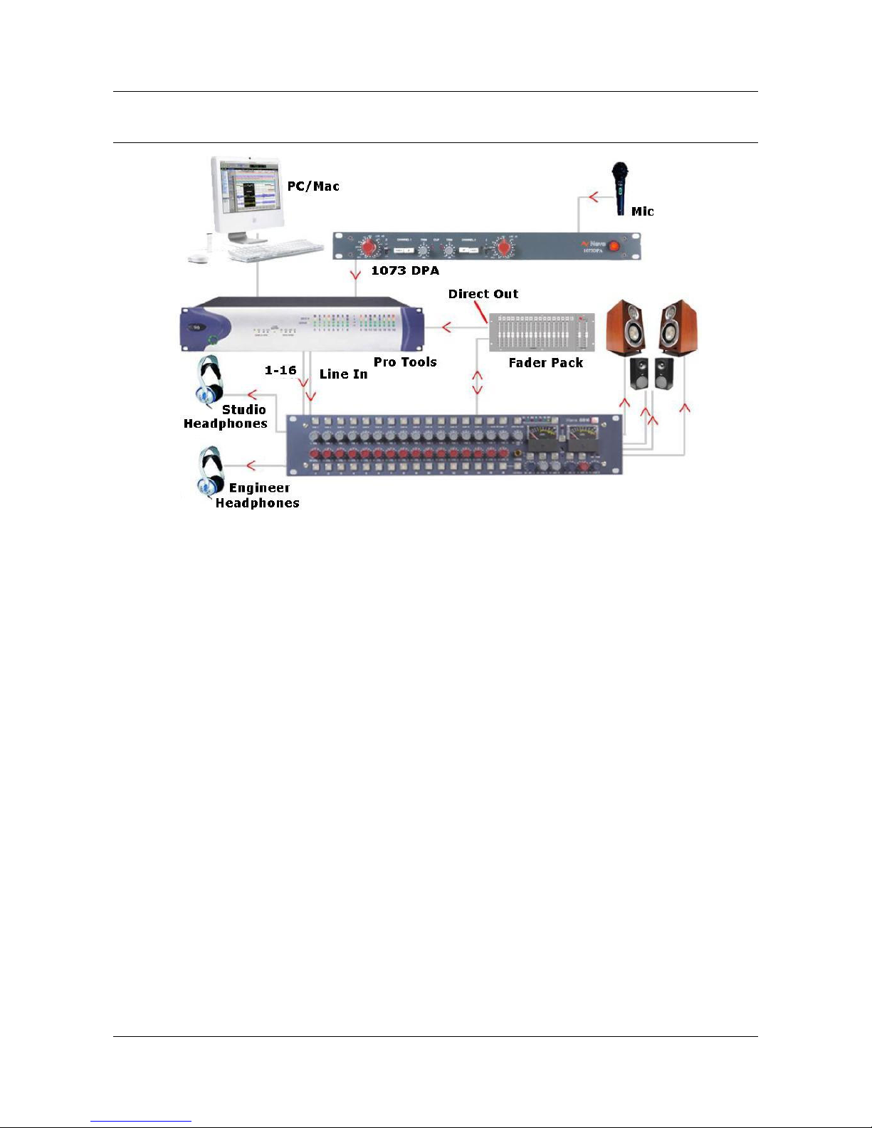
Recording..................................................................................................................6
Recording with optional Fader Pack...............................................................................7
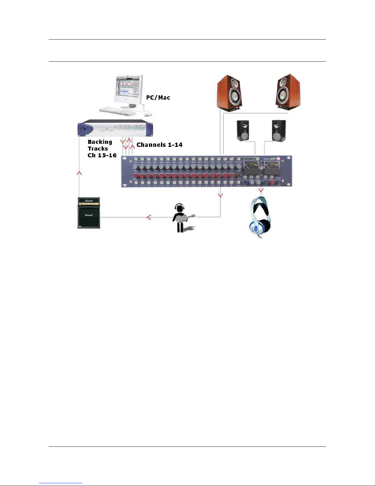
verdubbing..............................................................................................................8
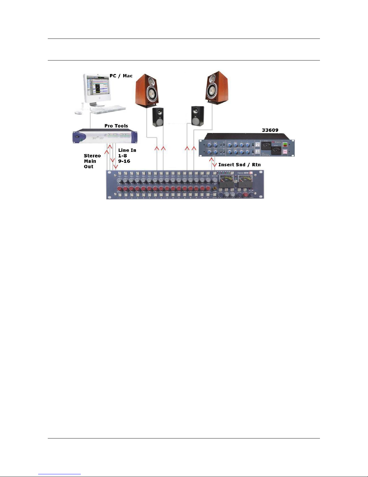
Mixing.......................................................................................................................9
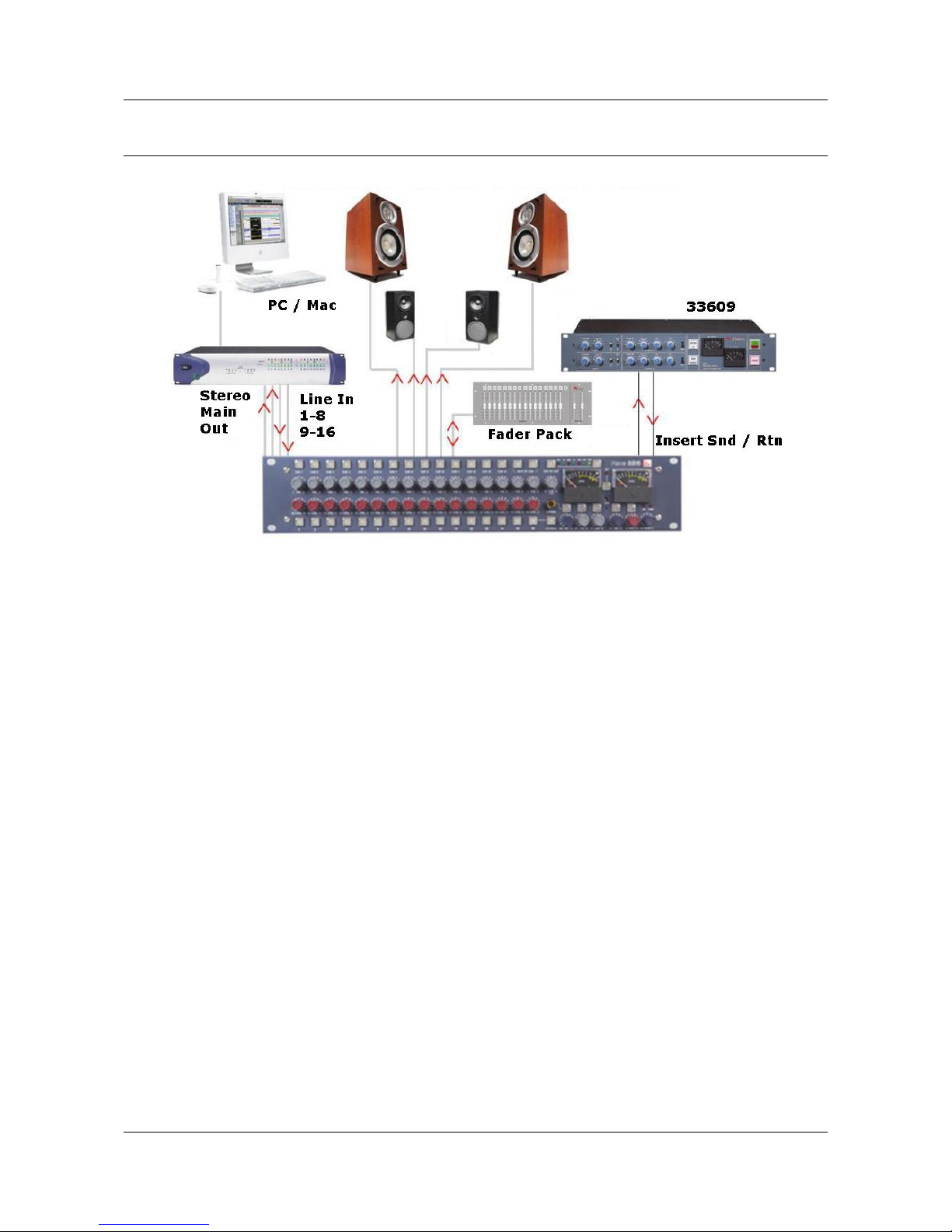
Mixing with Fader Pack..............................................................................................10
Mastering................................................................................................................11
Live Recording.........................................................................................................12
Sub Mixer................................................................................................................13
3 - Con rols.......................................................................................................14
Channel Strip.......................................................................................................14
Level Control........................................................................................................14
Pan Control..........................................................................................................14
Cue Control Button...............................................................................................14
Channel Cut /Solo button.......................................................................................14
Cue Section.............................................................................................................15
2T to Cue............................................................................................................15
Headphone Mon...................................................................................................15
Headphone Control...............................................................................................15
Headphone Jack...................................................................................................15
4 - Mas er Sec ion.............................................................................................16
Alt Spk................................................................................................................16
iMon...................................................................................................................16
Talkback Level.....................................................................................................16
Talkback Microphone.............................................................................................16
INS MIX .............................................................................................................16
IMR Level Control.................................................................................................16
INS.....................................................................................................................16
2TR MIX..............................................................................................................17
2TR Level Control.................................................................................................17
Monitor Selections................................................................................................17
Mon Level............................................................................................................17
Sum....................................................................................................................17
Width Control.......................................................................................................17
<W> button.........................................................................................................17
Mix Level.............................................................................................................18
Analogue / Digital overload indication......................................................................18
Metering..............................................................................................................18
Power Switch.......................................................................................................18
5 - Op ions........................................................................................................19
Fader Pack ption....................................................................................................19
ADC ption..............................................................................................................19
Sampling Frequency..............................................................................................19
Double Rate AES utput........................................................................................19
DSD....................................................................................................................19
- Page 3 -