Atlas AR-130 User manual

AR - 130
ATLAS
AR-130 RESIDENTIAL & COMMERCIAL
INSTALLATION GUIDE
Please read this installation guide carefully to ensure
correct installation of the AR-130 Vertical Platform Lift.
Rev. August 15th, 2018
p/n: 999355-0018

ATLAS AR-130 VERTICAL PLATFORM LIFT
This manual describes how to install the Atlas AR-130 Vertical Platform Lift.
The Atlas AR-130 sleek and compact vertical platform lift that is designed for today’s
modern residences. The AR-130 model provides the user with a seamless and safe
experience. A series of safety features including; emergency stop buttons, emergency
lowering device and detection safety sensors offer the peace of mind when operating
the lift.
Refer to the Atlas AR-130 Vertical Platform Lift Owner’s Manual for details regarding
operation and maintenance. The Owner’s Manual can be found on our website: www.
atlasacces.com
TECHNICAL SPECIFICATIONS
Load Capacity 750 LBS 340 KG
Rated Travel Speed 24 FPM 0.12 M/S
Drive Type TRACTION CABLES
Pit Depth 4” 101.60 MM
Maximum Travel 276” 7.01 M TO 433” 11.00
Codes and Standards CSA B613-00 & B355-15
Advantages COMPACT AND QUIET

DISCLAIMER
LES ESCALATEURS ATLAS, INC. (Collectively, “Les Escalateurs Atlas”, “Atlas” and
“Manufacturer”) shall not be held responsible or liable for any personal injury or
property damage caused by or resulting from inappropriate operation of original
product or of a product that has been modified or altered from the original AR-130
design. No person or company is authorized to change the AR-130 design without
authorization and the express written consent of LES ESCALATEURS ATLAS, INC.
IMPORTANT
Do not throw away, destroy, or lose this installation guide. The instructions included in
this guide must be followed to prevent product malfunction, property damage, injury,
or death to the user or other people. Incorrect operation due to ignoring instructions
found in this guide can cause harm, damage, injury or death. A summary of safety
precautions is found below.
For more technical materials such as drawings and specifications, end user support,
and manuals, visit www.atlasacces.com
WARNING
Read all instructions contained in this installation guide before installing the Atlas
AR-130 Vertical Platform Lift. It is highly recommended to observe and adhere to all
governing codes and ordinances in the job site locale. This includes ensuring all work
and materials comply and conform with all authorities having jurisdictions. Proper
installation is the responsibility of the installer and failure to follow all instructions
renders the Atlas Limited Warranty null and void.
SAFETY PRECAUTIONS
Safety of personnel is the primary concern during all procedures. Before beginning
installation, read and understand the installation guide and containing procedures
carefully to ensure correct and safe installation. Use the appropriate tools and
accessories during installation. Plan your work and do not work alone, if possible.
Know how to obtain emergency medical and fire fighting assistance.
Be sure to follow all the precautions below as they are important for ensuring safety.
This installation guide classifies the safety precautions into DANGER, WARNING,
CAUTION and NOTE.
DANGER Indicates an imminently hazardous situation which, if not avoided, will
result in death or serious injury.
WARNING Failure to follow any of WARNING is likely to result in such grave
consequences as death or serious injury
CAUTION Failure to follow any of CAUTION may in some cases result in grave
consequences.
NOTE Provides information such as reminders and guidelines and do not fit
into the preceding text.

The Atlas AR-130 Vertical Platform Lift shall be installed and serviced only by an
authorized Les Escalateurs Atlas, INC. Dealer only. The authorized dealer should refer
to this guide for installation and servicing. For Care & Troubleshooting, please refer to
the AR-130 Vertical Platform Lift Owner’s Manual.
Please carefully read and follow the instructions found in this guide BEFORE installing
and/or operating the Atlas AR-130 Vertical Platform Lift. Improper installation,
adjustment, service, use or maintenance can cause personal injury or property
damage. If you have any problems or need assistance please contact your dealer
immediately.
Failure to comply the these Installation Safety Instructions could render the Atlas
Limited Warranty null and void. If you have any question or concerns that are not
covered in this installation guide, please contact your dealer immediately.
NOTE
WARNING - To reduce the risk of fire, electric shock, personal injuries, and/or death,
obey the following precautions:
• Never exceed the maximum rated lift
capacity.
• Never use the Atlas AR-130 Vertical
Platform Lift to lift freight or other
materials than intended by design.
• Read and understand the installation
guide prior to installing the Atlas
AR-130 Vertical Platform Lift.
• Wear appropriate safety protection
equipment for your head, eyes, hands
and feet during all phases of the
installation.
• Use extreme caution when lifting
components into position to avoid
personal injury and damage to the
equipment.
• Keep panels and protective coverings
in place to avoid potentially fatal injury.
• Disconnect power from the unit before
performing any electrical or mechanical
service operations.
• Never bypass sensor switches which
prevent accidental start up when
protective panels are removed.
• Be aware of the location of others in
the work zone.
• Do not wear jewelry or loose clothing.
• Lock the wheels of any mobility device
riding on the platform.
• Use only recommended anchor
fasteners.
• Check and verify for applicable local
codes and regulations.
IMPORTANT FOR THE INSTALLER
INSTALLATION SAFETY INSTRUCTIONS
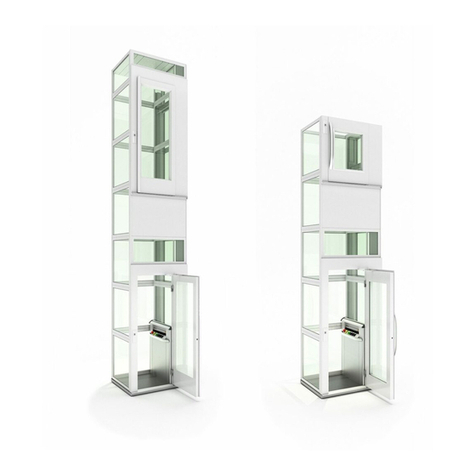
TABLE OF CONTENTS
CODES AND STANDARDS 6
SITE REQUIREMENTS 6
ELECTRICAL REQUIREMENTS 6
BEFORE YOU GET STARTED 6
HARDWARE LIST 7
AR-130 INSTALLATION 8
1. REMOVE CARRIAGE FROM LOWER RAIL ASSEMBLY 8
2. INSTALL LOWER RAIL ASSEMBLY 9
3. INSTALL UPPER RAIL ASSEMBLY 10
4. CUT A HOLE FOR THE DRIVE UNIT 11
5. INSTALL THE DRIVE UNIT SHELF 12
6. INSTALL THE DRIVE UNIT SHIELD 12
7. INSTALL THE DRIVE UNIT BASE 13
8. DISASSEMBLE THE DRUM SHAFT ASSEMBLY 13
9. INSTALL THE DRUM SHEAVE 14
10. PREP THE DRIVE SHAFT 15
11. INSTALL THE DRIVE MOTOR 15
12. INSTALL THE DRIVE MOTOR POWER CABLE 16
13. INSTALL AND WIRE THE BATTERIES 17
14. MOUNT CARRIAGE TO LOWER RAIL ASSEMBLY 18
15. INSTALL TIMING BELT AND TENSION RELEASE 19
16. INSTALL CABIN CONTROL PANEL FLAT CABLE 20
17. INSTALL EMERGENCY PIT SWITCH 21
18. WIRE IN THE AR-130 POWER SUPPLY 21
19. INSTALL LIMIT/CAM & MECHANICAL STOPS 22
20. INSTALL THE MANUAL LOWERING DEVICE 23
21. INSTALL THE ELEVATOR FLOOR 24
22. ASSEMBLE CABIN SIDE PANELS 25
23. ASSEMBLE 0° CABIN BACK PANEL(OPTIONAL) 26
24. MOUNT CABIN SIDE PANELS TO FLOOR 27
25. INSTALL EMERGENCY EXIT TOP FRAME 28
26. INSTALL CABIN BACK PANEL 29
27. INSTALL CABIN SIDE PANEL WALL FINISHINGS 30
28. INSTALL COP SIDE WALL FINISHINGS 31
29. INSTALL CEILING AND FINISHINGS 32

The AR-130 Vertical Platform Lift has been designed to meet CSA B613-00 & B355-15
standards. Code requirements and standards for vertical platform lifts vary depending
on location and region. It is the installer’s responsibility to contact their local code
enforcement office and determine all of the regulations they are subject to before
installing the AR-130 Vertical Platform Lift.
The AR-130 Vertical Platform Lift requires a 110VDC-15 AMP grounded electrical
circuit and a GFCI protected circuit. Depending on local codes and regulations, this
connection may need to be routed in electrical conduit and hard-wired.
- Upon receipt of the AR-130 Vertical Platform Lift, verify the lift for shipping damage
immediately. Report any discrepancies or damage claims to your dealer.
- Carefully verify all the site specifics, technical drawings and all preparatory work
prior to installation.
The AR 130 must be installed on a Supporting Wall and Floor that is capable of
supporting the minimum load and standards as laid out in the Technical Drawings.
Please read and verify with the Technical Drawings before beginning the installation of
the AR-130.
CODES AND STANDARDS
ELECTRICAL REQUIREMENTS
BEFORE YOU GET STARTED
SITE REQUIREMENTS
DO NOT OPERATE OR RIDE ON THE LIFT UNTIL IT HAS BEEN ANCHORED TO AN APPROVED PAD OR
FLOOR.
WARNING
6 AR-130 INSTALLATION GUIDE 888-773-6708 www.atlasacces.comATLAS

Before beginning installation, please inspect and check the box contents. Report any
missing or damaged parts to your dealer. All AR-130 Vertical Platform Lifts come with a
Standard AR-130 HARDWARE KIT.
HARDWARE LIST
AR-130 HARDWARE KIT
QTY NAME SIZE
35 FLAT HEAD MACHINE SCREW 1/4”-20 X 3/4”
12 PAN HEAD WOOD SCREW 1/2”-#8
20 HEX BOLT 1/4”-20 X 3/4”
10 TRUSS PHILLIPS STAINLESS STEEL SCREW 1/4”-20 X 3/4”
12 NUT 1/4”-20
25 WASHER 1/4”
25 LOCK WASHER 1/4”
20 TRUSS PHILLIPS STAINLESS STEEL SCREW 1/4”-20 X 1-1/2”
4 TRUSS PHILLIPS STAINLESS STEEL SCREW #8-32 x 1/2”
4 TRUSS PHILLIPS STAINLESS STEEL SCREW #8-32 x 1”
4 COUPLING NUT #8-32
7AR-130 INSTALLATION GUIDE 888-773-6708 www.atlasacces.comATLAS

PROCEDURE
Remove the Carriage from the Lower Rail Assembly.
INSTALL
1. Remove the 4 Carriage Roller Assemblies and Support Brackets. ENSURE TO TAKE
NOTE AND KEEP THE SAME HEX BOLT CONFIGURATION FOR LATER REASSEMBLY.
AR-130 INSTALLATION
1. REMOVE CARRIAGE FROM LOWER RAIL ASSEMBLY
Hex Bolts
(3/8”-16 X 3-1/4”)
Hex Bolts
(3/8”-16 X 3”)
Carriage Roller Assembly
Support Bracket
Side Roller Calibration
Set Screw and Nut.
CARRIAGE AND RAIL ASSEMBLY
8 AR-130 INSTALLATION GUIDE 888-773-6708 www.atlasacces.comATLAS

PROCEDURE
Install the Lower Rail Assembly and it’s components on the Supporting Wall.
INSTALL
1. Align and position the Lower Rail Assembly according to the cabin dimensions and
technical drawings.
2. Ensure that the bottom of the Lower Rails rest flush and directly on the floor.
3. Mount the Lower Rail Assembly to the Supporting Wall by attaching a Lag Screw
(#14-4”) to each side of each Horizontal Bracing. MAKE SURE THAT YOU USE THE
PREDRILLED HOLES FOUND ON THE HORIZONTAL BRACING.
2. INSTALL LOWER RAIL ASSEMBLY
Refer to the number on the top middle
Horizontal Brace on each Rail Assembly
to know it’s position.
XXX / XXX
Lag Screw
(#14-4”)
Supporting Wall
Horizontal
Bracing
WHEN MOUNTING THE RAIL ASSEMBLY TO
THE SUPPORTING WALL. ALWAYS USE THE
PREDRILLED HOLES THAT INTERSECT THE
RAIL AND THE HORIZONTAL BRACING WHEN
MOUNTING RAIL ASSEMBLY TO SUPPORTING
WALL.
WARNING
9AR-130 INSTALLATION GUIDE 888-773-6708 www.atlasacces.comATLAS

PROCEDURE
Install the Upper Rail Assembly on top of the Lower Rail Assembly.
INSTALL
1. Align and place the Upper Rail Assembly on top of the Lower Rail Assembly.
2. Ensure that the bottom of the Upper Rails rest flush on top of the Lower Rail
Assembly.
3. Secure the Upper Rail Assembly to the Lower Rail Assembly using 2 Hex Bolts (1/4”-
20 X 1”) on each side.
4. Attach the Upper Rail Assembly to the Supporting Wall using a Lag Screw (#14-4”)
on each side. ONLY USE THE PREDRILLED HOLES FOUND ON THE RAIL AND THE
HORIZONTAL BRACING.
3. INSTALL UPPER RAIL ASSEMBLY
Lag Screw (#14-4”)
Horizontal Bracing
Horizontal Bracing
Hex Bolts (1/4-20 by 1”)
Rail
Lower and Upper Rail Assembly.Lower Rail Assembly
ALWAYS USE THE PREDRILLED HOLES THAT
INTERSECT THE RAIL AND THE HORIZONTAL
BRACING WHEN MOUNTING RAIL ASSEMBLY
TO SUPPORTING WALL.
WARNING
10 AR-130 INSTALLATION GUIDE 888-773-6708 www.atlasacces.comATLAS

PROCEDURE
Cut out a hole in the Supporting Wall for the Drive Unit.
INSTALL
1. Measure a 27” (68.58cm) x 19” (48.26cm) hole in the Supporting Wall above the
uppermost Rail Assembly. THE MEASURED HOLE SHOULD BE CENTERED TO THE
RAIL ASSEMBLY.
2. After measuring and verifying the correct measurements, cut out the hole.
4. CUT A HOLE FOR THE DRIVE UNIT
27” (68.58 cm)
CENTERED
19” (48.26 cm)
THE HOLE MUST BE CENTERED TO THE RAIL
ASSEMBLY
WARNING
11AR-130 INSTALLATION GUIDE 888-773-6708 www.atlasacces.comATLAS

PROCEDURE
Install the Drive Unit Shield.
INSTALL
1. Insert the Drive Unit Shield into
position.
2. Attach the Drive Unit Shield to
the Supporting Wall studs using 6
Wood Screws (#8-1-1/2”).
5. INSTALL THE DRIVE UNIT SHELF
6. INSTALL THE DRIVE UNIT SHIELD
PROCEDURE
Install the Drive Unit Shelf on top of the uppermost Rail Assembly.
1. Place and fasten the Lower Drive Unit Shelf to the uppermost Rail Assembly using a
Hex Bolts (3/8”-16 X 1”) on each side.
2. Fasten each side of the Upper Drive Unit Shelf into the studs using 2 Lag Screws
(#14 -4”).
Hex Bolt (3/8”-16 X 1”)
Upper Drive Unit Shelf Lower Drive Unit Shelf
Lag Screw (#14-4”)
Wood Screw (#8-1-1/2”) Drive Unit Shield
12 AR-130 INSTALLATION GUIDE 888-773-6708 www.atlasacces.comATLAS

Hex Bolt (3/8”-16 x 3/4”)
Drive Unit Base Drive Unit Shelf
PROCEDURE
Disassemble the Drum Shaft
Assembly.
INSTALL
1. Loosen the Set Screws located
on Locking Bearing and on the
Drum Shaft.
2. Slide and remove the Drum Shaft
and Key.
PROCEDURE
Install the Drive Unit Base.
INSTALL
1. Secure the Drive Unit Base to the Drive Unit Shelf using 6 Hex Bolts (3/8”-16 x
3/4”).
7. INSTALL THE DRIVE UNIT BASE
8. DISASSEMBLE THE DRUM SHAFT ASSEMBLY
Locking
Bearing
Key
Drum Shaft
Set Screw
Drum Shaft
Locking
Bearing
Set Screw
13AR-130 INSTALLATION GUIDE 888-773-6708 www.atlasacces.comATLAS

9. INSTALL THE DRUM SHEAVE
PROCEDURE
Install the Drum Sheave and reassemble the Drum Shaft Assembly.
INSTALL
1. Place the Drum Sheave into position and insert the Drum Shaft and Key.
2. Tighten the Set Screws on each side of the Drum Shaft. ENSURE THE SET SCREWS
ARE FIRMLY FASTENED TO THE DRUM KEY AND SHAFT.
3. Unroll the two cables on the Drum Sheave until they are around 24” (60.96 cm)
from the ground. ALWAYS KEEP A MINIMUM OF ONE AND A HALF TURNS OF THE
CABLE AROUND THE DRUM SHEAVE.
Set Screw
Locking
Bearing
Set Screw
ENSURE THE SET SCREWS ARE
FIRMLY FASTENED TO THE DRUM
KEY AND SHAFT.
ENSURE THAT THE THERE IS AT
LEAST ONE AND A HALF TURNS
OF CABLE AROUND THE DRUM
SHEAVE
CAUTION
VERIFY THAT THE JACK BOLT HAS BEEN PROPERLY
ADJUST AFTER DRUM SHEAVE INSTALLATION.
DANGER Set Screw
14 AR-130 INSTALLATION GUIDE 888-773-6708 www.atlasacces.comATLAS
Jack
Bolt

10. PREP THE DRIVE SHAFT
1. Install the Drive Motor and fasten it with 4 Hex Bolts (3/8”-16 x 3/4’’). THE
SOLENOIDS ON THE DRIVE MOTOR SHOULD ALWAYS BE FACING FRONT AND EASILY
ACCESSIBLE.
2. Install the Cable Detection Assembly. Ensure the space between the Bottom of the
Pad and the Cable is the width of two cables.
11. INSTALL THE DRIVE MOTOR
PROCEDURE
Install the Coupler, Coupler Ring and Key onto the Drive Shaft.
INSTALL
1. Insert the Key into the Key Seat and slide the Coupler onto the Drive Shaft, keeping
the Coupler Keyway aligned with the Key.
2. Slide and insert the Coupler Ring into the Coupler.
Solenoids Drive Motor
Hex Bolt
(3/8”-16 x 3/4’’).
Cable Detection Pad Cable Detection Assembly
Coupler
0.5” (12.7 MM)
Coupler
Assembly
Coupler RingKey Seat
Key
THE COUPLER ASSEMBLY SHOULD BE 0.5 INCH 12.7 MM FROM THE DRIVE SHAFT BASE.
CAUTION
15AR-130 INSTALLATION GUIDE 888-773-6708 www.atlasacces.comATLAS

PROCEDURE
Install the Drive Motor Power Cable to the Drive Motor.
INSTALL
1. Locate the Drive Motor Power Cable (Rolled up near the Control Panel).
2. Wire and connect the Drive Motor Power Cable to the Drive Motor using the
provided Electrical Diagram.
Control Panel
Drive Motor Power Cable
12. INSTALL THE DRIVE MOTOR POWER CABLE
Drive Motor Solenoid
Drive Motor
16 AR-130 INSTALLATION GUIDE 888-773-6708 www.atlasacces.comATLAS

13. INSTALL AND WIRE THE BATTERIES
INSTALL
1. Remove the Control Panel Cover.
2. Before installing the batteries, ensure that the Protective Plate is properly installed
in the Tower underneath the batteries.
3. Place the two 12V Batteries into position and wire according to the Wiring Diagram.
FIG. X PROTECTIVE PLATE
Control Panel Cover
12V Battery
17AR-130 INSTALLATION GUIDE 888-773-6708 www.atlasacces.comATLAS

INSTALL
1. Position the Carriage adjacent to the Rail Assembly.
2. Secure the Carriage to the Rail Assembly by reinstalling the 4 Carriage Roller
Assemblies. ENSURE TO INSTALL USING THE SAME HEX BOLT CONFIGURATION
FROM STEP 1.
3. Attach the Steel Wire Rope to the Wedge Sockets.
14. MOUNT CARRIAGE TO LOWER RAIL ASSEMBLY
Hex Bolts (3/8”-16 X 3-1/4”)
Hex Bolts (3/8”-16 X 3”)
Carriage Roller Assembly
Support Bracket
SIDE VIEW OF AN
INSTALLED WEDGE SOCKET
Side Roller Calibration
Set Screw and Nut.
18 AR-130 INSTALLATION GUIDE 888-773-6708 www.atlasacces.comATLAS

INSTALL
1. Attach the Timing Belt and Timing Belt Clamp to the Drive Unit Shelf. ENSURE THE
TIMING BELT’S COGGED RUBBER TEETH FACE TOWARDS THE CARRIAGE.
2. Thread the Timing Belt through the Speed Governor. REFER TO THE TIMING BELT
DIAGRAM ON THE SPEED GOVERNOR.
3. Attach the bottom of the timing belt to the bracket on the Tension release
assembly.
15. INSTALL TIMING BELT AND TENSION RELEASE
ENSURE THAT THERE IS NOT TOO MUCH TENSION ON THE TIMING BELT. EXCESSIVE TENSION ON
THE TIMING BELT CAN DAMAGE THE TIMING BELT AND COMPROMISE OTHER COMPONENTS.
WARNING
Timing Belt
Tension Release Spring
Tension Release
Assembly Bracket
Timing Belt
Speed Governor Assembly
19AR-130 INSTALLATION GUIDE 888-773-6708 www.atlasacces.comATLAS

16. INSTALL CABIN CONTROL PANEL FLAT CABLE
PROCEDURE
Fasten the Cabin Control Panel Flat Cable into position.
INSTALL
1. Hold the Flat Cable in position and fasten to the Horizontal Bracing using 1 Bracket
and 2 Pan Head Screws (#10 X 1”) at each fastening point. ENSURE THAT THE
SLACK ON THE CABIN CONTROL PANEL FLAT CABLE IS MINIMAL. TOO MUCH
SLACK WILL RISK THE FLAT CABLE BEING PINCHED BETWEEN THE CARRIAGE AND
CONTROL PANEL.
Horizontal Bracing
Bracket and 2 Pan Head Screws (#10 X 1”)
Cabin Control Panel Flat Cable
ENSURE THAT THE SLACK ON THE
CABIN CONTROL PANEL FLAT CABLE
IS MINIMAL. TOO MUCH SLACK WILL
RISK THE FLAT CABLE BEING PINCHED
BETWEEN THE CARRIAGE AND CONTROL
PANEL.
WARNING
20 AR-130 INSTALLATION GUIDE 888-773-6708 www.atlasacces.comATLAS
Table of contents