Atlas Kaye AC-MGM2W User manual

•
''--
aye
Wall Mounted
Oscillating Fan
READ AND SAVE THESE INSTRUCTIONS
FAN RATING AC 120V 60Hz
MODEL: AC-MGM2W

OOLS AND MA ERIALS
REQUIRED
Philips screw driver
Standard, flat-head screw driver
11 mm wrench
Step ladder
Wire cutters
PACKAGE CON EN S
Unpack your fan and check the contents. You
should have the following items:
~~
a. Fan motor assembly
b. Canopy
c. Hanger bracket
d. Wall control with 2 mounting screws
e. Mounting plate with 2 mounting screws
f. Allen wrench
g. Mounting hardware:
wood screws (4), screws (4),
lock washers (4), washers (4),
star washers (4), wire nuts (3)
a
0
0
;@
d
n[3]l~
Cj
c
9
1
19Je

EAD AND SAVE THESE SAFETY AND
INSTAllATION INST UCTIONS.
Consult a licensed electrician if unsure of any point below mentioned.
DANGE IW A N ING/CAUTION
. WA NING: TO REDUCE THE RISKS OF FIRE, ELECTRIC SHOCK OR INJURY TO
PERSONS, OBSERVE THE FOllOWING:
A. Use this unit only in the manner intended by the manufacturer. If you have any questions,
contact the manufacturer.
B. Before servicing or cleaning unit, switch power off at service panel and lock the service
disconnecting means to prevent power from being switched on accidentally. When the
service disconnecting means cannot be locked, securely fasten a prominent warning device,
such as a tag, to the service panel.
C. Installation work and electrical wiring must be done by qualified persons in accordance with
all applicable codes and standards including fire-related construction.
D. When cutting or drilling into wall or ceiling, do not damage electrical wiring and other hidden
utilities.
2. High voltage and moving parts around motors and motor driven equipment can cause
serious or fatal injuries. Always disconnect power source at main switch before wiring,
servicing or cleaning unit. Do not rely on fan control device to prevent unexpected start-up
or electrical shock. In addition, power supply must have fuses or circuit breakers for short
circuit protection.
3. All electrical wiring must be performed by qualified persons in accordance and conform
withal applicable national and local electrical codes such as: NEC, OSHA, etc.
4. Fan should be secure in its electrical grounding to avoid possible electrical shock.
5. Fan should not be used in any wet or hazardous location defined by article 500 of the NEC.
In addition, its ambient temperature should not exceed 04 degrees Fahrenheit.
6. Power supply should conform to voltage rating of 5V.
7. Before applying power, visually re-inspect the installation. Make sure that all guards and
protective devices are securely in place and all visible screws and bolts are tightened. All
set-screws must be retightened before installation.
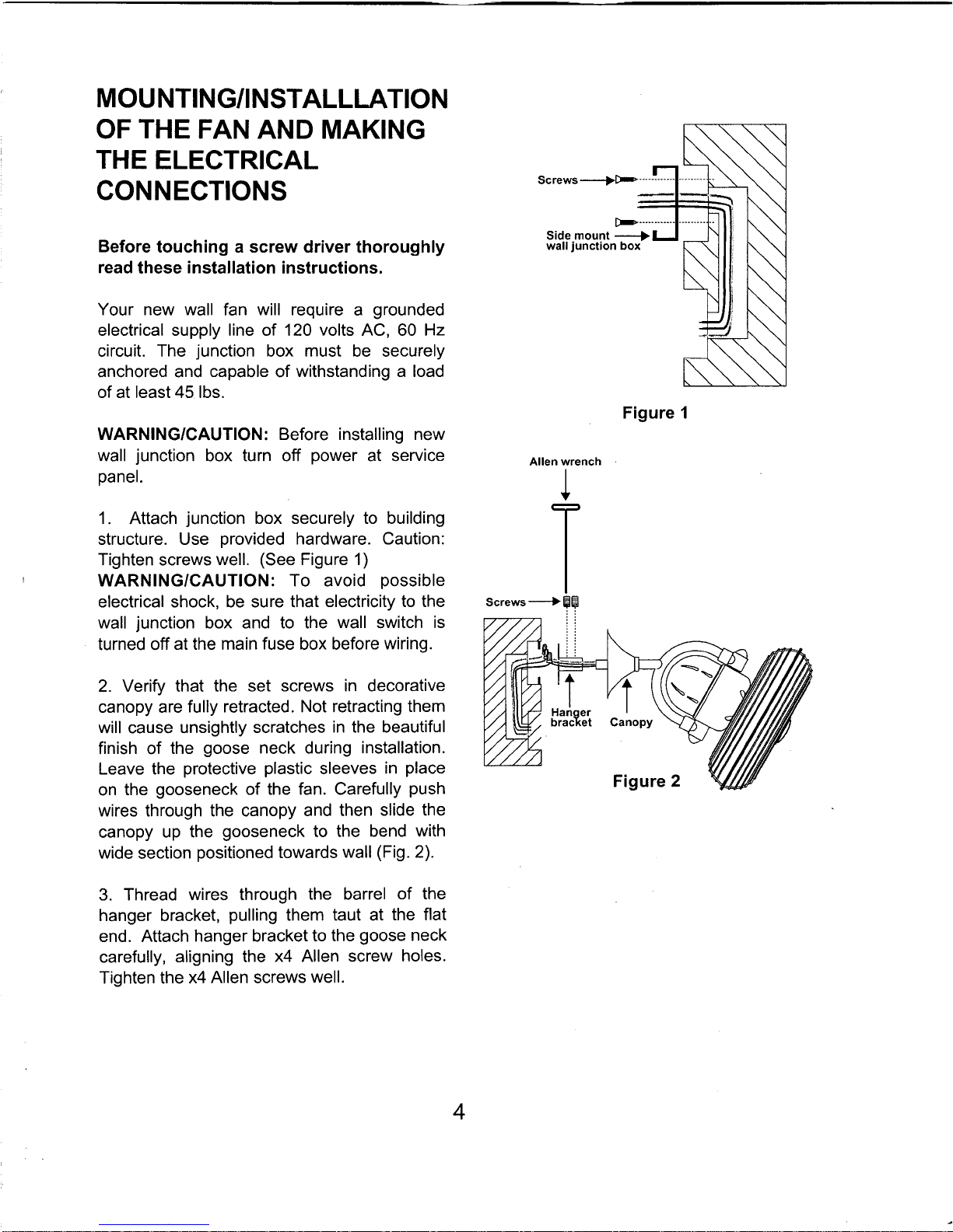
8. WA NING: to reduce the risk of fire, electrical shock or personal injury, mount hanging
bracket to outlet box marked "Acceptable for fan support and a hanging weight of 45 lbs."
Do not mount fan to sheet rock or drywall type materials and use only the screws provided
with the outlet box.
2

. AUTION: to reduce the risk of injury to persons, install fan so that bottom edges of fan
blades are to be: In Canada, to satisfy CSA requirements: at least 8.3 Ft/2.5 M above the
floor and all objects in room. In the US, to satisfy UL requirements: at least 7.0 Ft above the
floor and all objects in room.
ATTENTION: Installer de sorte que les pieces inferieures soient a au moins 2.5 metres
au-dessus du plancher ou du sol.
10. To reduce the risk of personal injury, do not bend blades or any other part of fan when
cleaning. Do not insert foreign objects in between rotating fan blades or in space
surrounding entire rotating fan unit. Fan must be turned off at power at supply source before
installation, cleaning or servicing.
11. After making the wire connections in junction box, the wires should be spread apart with the
grounded conductor and the fan-grounding conductor on one side of the junction box and
the ungrounded conductor on the other side of the outlet box. Be sure that all wiring
connections are properly insulated from each other and any surrounding metal parts. For
safety and best operating results, we recommend' that you have a qualified electrician
assemble and install your fan.
12. To reduce the risk of personal injury, install the supplementary mounting means and use
only the hardware provided with the fan.

OUNTING/INSTALLLA TION
OF THE FAN AND AKING
THE ELECTRICAL
CONNECTIONS
Before touching a screw driver thoroughly
read these installation instructions.
our new wall fan will require a grounded
electrical supply line of 120 volts AC, 60 Hz
circuit. The junction box must be securely
anchored and capable of withstanding a load
of at least 45 Ibs.
WARNING/CAUTION: Before installing new
wall junction box turn off power at service
panel.
1. Attach junction box securely to building
structure. Use provided hardware. Caution:
Tighten screws well. (See Figure 1)
WARNING/CAUTION: To avoid possible
electrical shock, be sure that electricity to the
wall junction box and to the wall switch is
turned off at the main fuse box before wiring.
2. Verify that the set screws in decorative
canopy are fully retracted. Not retracting them
will cause unsightly scratches in the beautiful
finish of the goose neck during installation.
Leave the protective plastic sleeves in place
on the gooseneck of the fan. Carefully push
wires through the canopy and then slide the
canopy up the gooseneck to the bend with
wide section positioned towards wall (Fig. 2).
3. Thread wires through the barrel of the
hanger bracket, pulling them taut at the flat
end. Attach hanger bracket to the goose neck
carefully, aligning the x4 Allen screw holes.
Tighten the x4 Allen screws well.
4
Screws-.e- .
- .
Sidemount -.
walljunction box
Figure 1
Allenwrench
~
T
screws-+~~
Figure 2

. Connect the neutral fan wire to the
household neutral wire. (Fig. 3)
A. Single Circuit Connection Oscillation
and fan motor action are not separate.
Connect the black, hot fan blade motor wire to
the blue, hot oscillating motor wire. Attach
these two wires to the hot, household supply
wire. (Fig. 3)
8. Two/Dual Circuit Connection Oscillation
motor can be regulated apart from fan motor.
Connect the black, hot fan blade motor wire to
a hot, household supply wire. Connect the
blue, hot oscillating motor wire to the second
hot, household supply wire. (Fig. 3)
6. Connect the green, fan ground wire to the
household ground wire.
7. After connecting the wires, spread them
apart so that the green, ground and neutral,
white wires are on one side of the outlet box
and the hot, black and blue wires are on the
other side of the outlet box.
8. Attach fan/hanger bracket wall junction box
using hardware provided. Tighten screws well.
(Fig. )
9. Push canopy down goose neck toward wall
until the canopy lays flat against the wall
surface, covering junction box and mounting
plate. Tighten set screws in canopy. (Fig. )
5
o
Figure 3
Figure 4

OUNTING/INSTALLATION
OF THE WALL CONTROL
. Remove the existing wall plate and switch.
(Fig. 5)
2. Set knobs on the new, wall control in the
"0" position.
3. Make speed control wire connections (Fig.
6). Ensure that bare wires are fully inserted
into their terminals with no loose strands
and that terminal screws are fully tightened .
• Hot wire from fan blade motor to wall speed
control port labeled "Fan."
• Hot wire from oscillation motor to wall speed
control labeled "Oscillation". Note: Perform
this step if yours is a two/dual circuit
installation. If this is a single circuit
application, this step will be ignored and the
blade motor and oscillation motor will not be
operated independently.
• Hot, household supply wire to wall speed
control port labeled "To Hot."
Switch
/ Screws
._- .. /
--1!lDJI@
Figure 5
HoI black/while household supply
Blue/Hollo OSC. (fan)
Green ground lead
Black/Hot 0fan
Figure 6
4. Connect, if present, the wall speed control's
ground wire directly to one of the screws
from the outlet box. (Fig. 7)
5. Attach the wall control to the outlet (wall)
box and secure with 2 outlet box screws.
(Fig. 7)
6. Attach the wall plate to the wall speed
control and secure with 2 mounting
screws. (Fig. 7)
6
Screws
~
.....
o
Screws
Figure 7
Outlet box
/

PERATING THE WALL
C NTR L
estore Power to Wall Fan.
The fan 3-speed control knob is used to
control the fan blade speed as follows:
0= Turns the fan off
1= High Speed
2= Medium Speed
3= Low Speed
B. ON-OFF Button:
This button is used to regulate the oscillating
operation.
Figure 8
CARE F AND TR UBLESH TING Y UR FAN
1. Check hardware bi-yearly. Because of the fan's natural movement some connections may
become loose over time. Check the support connections, brackets and blade attachments
twice a year. Make sure they are secure. It is not necessary to remove fan from the wall.
2. Clean your fan periodically. This will help to help maintain its new appearance over the
years. Use only a lightly water-moistened, lint free cloth to avoid scratching the finish. Plated
finishes are sealed with lacquer to minimize discoloration or tarnishing. Do not let rain or
running water to come in contact with the fan. ain or running water could damage the motor
or possibly cause an electrical shock.
3. There is no need to oil your fan. The motor has permanently lubricated bearings.
4. Fan makes a vibration noise. Check to see that all screws are tight in the fan cage
connection to the motor face plate.
5. Fan vibrates or makes grinding noise as blades rotate. Uninstall and reinstall the blades.
Make sure that your fan head's set screw is counter-sunk into the bore hole in the flat part of
the motor shaft. Be careful that the blade brackets themselves are not bent in this process.
Do not operate your fan if it continues to vibrate. Contact your Atlas Fan Co purveyor if the
re-installation of the blades does not resolve the problem.
7
Other manuals for Kaye AC-MGM2W
1
Table of contents
Other Atlas Fan manuals

Atlas
Atlas HIGHPOINT INVISARIDGE User manual

Atlas
Atlas PERFORMANCE RIDGE User manual

Atlas
Atlas Melody AC-MGM2 User manual

Atlas
Atlas HGHPOINT Stealth Ridge User manual

Atlas
Atlas Diane User manual

Atlas
Atlas DAGNY User manual

Atlas
Atlas Irene User manual

Atlas
Atlas Donaire User manual

Atlas
Atlas Kaye AC-MGM2W User manual

Atlas
Atlas Trueridge ALL- WEATHER User manual