ATRAD ST-40 User manual

DESIGN AND MANUFACTURE OF ATMOSPHERIC RADAR SYSTEMS
ST-40
SYSTEM OPERATION
MANUAL
Copyright by ATRAD 2007
All Rights Reserved
ATRAD Pty Ltd
ABN 72 112 121 801
Thebarton SA 5031
1/26 Stirling Street
Australia
P/No: 15-05004 Issue 2 1
ATRAD

P/No: 15-05004 Issue 2 2

Table of Contents
1 ST-40 SYSTEM................................................................................... 5
1.1 OVERVIE ........................................................................................................................ 5
1.2 RACK LAYOUT.................................................................................................................5
2 SUB-RACK - DC POWER SUPPLY................................................... 8
2.1 OVERVIE ...................................................................................................................... 8
2.2 PS CONTROLLER...........................................................................................................9
2.3 PS RECTIFIER...............................................................................................................10
3 SUB-RACK – ST-20.......................................................................... 11
3.1 OVERVIE ...................................................................................................................... 11
3.2 PA DRIVER......................................................................................................................14
3.3 PA MODULE................................................................................................................... 16
3.4 PA CONTROLLER......................................................................................................... 20
3.5 RF DISTRIBUTION MODULE.....................................................................................23
4 SUB-RACK - RF POWER COMBINER............................................. 25
4.1 OVERVIE ...................................................................................................................... 25
5 ST-40 SYSTEM ASSEMBLY............................................................ 28
5.1 MECHANICAL ASSEMBLY....................................................................................... 28
5.2 ELECTRICAL ASSEMBLY......................................................................................... 28
5.3 RF CABLE ASSEMBLY................................................................................................28
6 REFERENCES.................................................................................. 2
P/No: 15-05004 Issue 2 3

List of Pictures
Picture 1. ST-40 Rack (Front View) 7
Picture 2. ST-40 Rack (Rear View) 7
Picture 3. Valere, L Series Compact Shelf, DC Power Supply 8
Picture 4. Valere, L Series Compact Shelf, DC Power Supply 8
Picture 5. Controller Display 9
Picture 6. Rectifier Insertion/Extraction 10
Picture 7. VHF PA Driver (Top View) 15
Picture 8. VHF PA Driver (Bottom View) 15
Picture 9. VHF PA Module (Top View) 17
Picture 10. VHF PA Module (Bottom View) 18
Picture 11. PA Controller (Front View) 19
Picture 12. PA Controller (Rear View) 19
Picture 13. RF Power Combiner (Rear View) 25
Picture 14. RF Power Combiner (Rear View) 25
List of Block Diagrams
Block Diagram 1. ST-40 Rack (Front) 6
Block Diagram 2. ST-40 Rack (Rear) 6
Block Diagram 3. ST-20 System 11
Block Diagram 4. ST-20 Sub-Rack (Rear) 12
Block Diagram 5. ST-20 Sub-Rack (Front) 12
Block Diagram 6. Tx Trigger Pulse 13
Block Diagram 7. VHF PA Driver 15
Block Diagram 8. VHF PA Module 17
Block Diagram 9. PA Controller 19
Block Diagram 10. VHF PA Controller (Front Panel Connectors) 20
Block Diagram 11. RF Distribution Module 22
Block Diagram 12. RF Distribution Module (Front Panel Connectors) 23
Block Diagram 13. ST-40 RF Power Combiner 24
P/No: 15-05004 Issue 2 4

1 ST-40 System
1.1Overview
Hardware Specifications
Operating Frequency Range 30-60 MHz
Peak Envelope Power 40 KW PEP (minimum)
VSWR(Input/Output) 1.5:1 (minimum)
Maximum PRF Dependent on pulse width and maximum Duty Cycle
Pulse Shape Gaussian Square
Maximum Duty Cycle 10 % Gaussian 12% Square
Output Spurious and Harmonics Better than –60 dBc
Impedance (Input/Output) 50Ω
Output Level Adjustable from 0 to 100%
Power Supply 50V DC (typical) 10KW (for max. Duty Cycle)
Ambient Temperature +5 to +35 oC
Sub-Rack Temperature +65 to +95 oC (60 oC rise for max. Duty Cycle)
Sub-Rack Mounting 19” rack mount
Cooling Forced air-cooled
1.2Rack Layout
The ST-40 VHF Transmitter is composed of a number of sub-systems here referred to as sub-racks. The
three main sub-racks are
1. DC Power Supply (x2)
2. RF Power Combiner (x1) and
3. ST-20 (x2) ( which is itself a VHF Transmitter).
Other components of the ST-40 include a Circuit Breaker/Distribution Panel Ethernet Switch and a Medium
Power 2-1 RF splitter. Please refer to Block Diagrams 1 & 2 for the front and rear view of these sub-racks in
the ST-40 cabinet.
Modularity is an important feature of the ST-40 design and as such critical sub-racks are modular. In
particular the ST-20 is composed of [1-6] RF PA Modules also a RF PA Driver Controller and Fan
module. The DC Power Supply is composed of a Controller module and [1-4] Rectifier modules. The
benefits of this modularity include:
1. Scalability in RF Output Power. From 4 KW to 40KW in steps of 4 KW.
2. Scalability in Duty Cycle. 0-10% with 4 Rectifier modules installed i.e 2 Rectifiers per ST-20 sub-
rack. With reduced PEP then operation with a Duty Cycle > 10% may be possible.
3. Maintenance upgrades & repairs.
4. Easy of Transport.
Please refer to the various sub-rack sections for module installation instructions also see Block Diagram [1-
2] and Pictures [1-4].
P/No: 15-05004 Issue 2 5

(5 RU)
(3 RU)
(1 RU)
(2 RU)
(1 RU)
(9 RU)
(1 RU)
(3 RU)
(1 RU)
(9 RU)
(1 RU)
(2 RU)
(1RU)
Blanking Panel /
Ethernet Switch
Circuit Breaker &
Distribution
Vent Panel
DC Power Supply
Vent Panel
ST-20
Vent Panel
RF Power Combiner
Vent Panel
ST-20
Vent Panel
DC Power Supply
Vent Panel
Block Diagram 1. ST-40 Rack (Front) Block Diagram 2. ST-40 Rack (Rear)
P/No: 15-05004 Issue 2 6

Picture 1. ST-40 Rack (Front View) Picture 2. ST-40 Rack (Rear View)
P/No: 15-05004 Issue 2 7

2 Sub-Rack - DC Power Supply
2.1 Overview
Picture 3. Valere, L Series Compact Shelf, DC Power Supply [4]
Picture 4. Valere, L Series Compact Shelf, DC Power Supply
The Valere Compact DC Power System (L Series Compact Shelf) accepts an AC Voltage between 180 and
264 VAC 47 to 63 Hz and produces a regulated output of 42-56 VDC capable of delivering a maximum of
200 Amperes (depending on the number of deployed Rectifiers i.e 50 Amperes per rectifier) in an ambient
operating temperature range of -40oC to +75oC. It boasts a typical conversion efficiency of 92%. Picture 5
shows the front panel of the DC Power System there are five modules. Two Rectifier modules fitted two
blank modules (which can be up replaced/upgraded with additional rectifiers) and a Controller module is to
the far left.
There is a Compact DC Power System associated with each ST-20 sub-rack. The Supply requirements for
the ST-20 will be dependent on user defined Duty Cycle. Typical power requirements for a 20 KW (PEP) RF
pulse set at 5% duty cycle is 2000 W (50V@40A). Typical power requirements for a 20 KW (PEP) RF pulse
set at 10% duty cycle is 4000 W (50V@80A).
For the AC and DC connection details please refer to [3]. The DC supply connection interface to the ST-20
is via 4 Powerpole Pak Connectors [5] on the rear of the ST-20 with a separate 6U panel dedicated and four
panel receptacles. Each Powerpole Pak Connector is capable of passing 50V@90A.
P/No: 15-05004 Issue 2 8

2.2 PS Controller
Picture 5. Controller Display [4]
This section refers to the BC Series Controllers menu's and
configuration options. In particular there are three menu
levels
1. Basic
2. Main
3. Administrator.
We will restrict ourselves to the Basic and Main menu as it is
recommended that the controller settings are not altered
without consultation care should be exercised in using the
Administrator menu. Appendix A of [4] contains the complete
menu tree for the controller. Further Navigation is via the
Controller's Front Panel and three button keypad (DN
MENU UP).
Basic Menu
After Power ON the controller should display “System OK”. The controller is now at the Basic menu level.
You can use the DN/UP buttons to view the basic plant parameters. The parameters of interest for the ST-20
sub-rack include- DC output voltage DC output current and internal temperature.
Main Menu
Hold the MENU button (on the Controller's front panel) down for 5 seconds the Main menu can now be
accessed.
By scrolling to the “Review” field and pressing the MENU button all the Power Supplies parameters can be
viewed (refer to the menu tree for navigation details Appendix A of [4]).
Within the Main menu by scrolling to the “Log In” field and pressing the MENU button the Administrator
Level is accessed (refer to the menu tree for navigation details Appendix A of [4]). The default password is
5001.
Please Note: It is recommended that the controller factory equipped default
settings are not altered without consultation
P/No: 15-05004 Issue 2 9
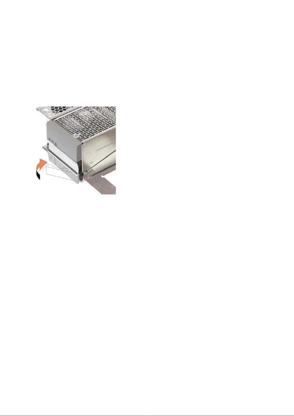
2.3 PS Rectifier
The modular plug-n-play nature of this Power Supply makes diagnostics and repair very easy. The rectifiers
are hot swappable modules which can be removed while the system is running without effecting operation.
Rectifier Model: V2500A Series 2:14 Input: [200-240 VAC 0-15A 50/60Hz] Output: [42-56 VDC 0-
50A].
PS Rectifier Installation
Picture 6. Rectifier Insertion/Extraction
To extract a rectifier push the “latch button” on the front of
the module and pull the “latch” open. This will remove the
rectifier from the back plane and disconnect it from the
system.
To insert a rectifier with the latch open and push the rectifier
into position. Once in position push the rectifier latch closed
as shown in Figure 8.
P/No: 15-05004 Issue 2 10
Table of contents
Popular Computer Hardware manuals by other brands

EMC2
EMC2 VNX Series Hardware Information Guide

Panasonic
Panasonic DV0PM20105 Operation manual

Mitsubishi Electric
Mitsubishi Electric Q81BD-J61BT11 user manual

Gigabyte
Gigabyte B660M DS3H AX DDR4 user manual

Raidon
Raidon iT2300 Quick installation guide

National Instruments
National Instruments PXI-8186 user manual


