ATSC AT2016 User manual
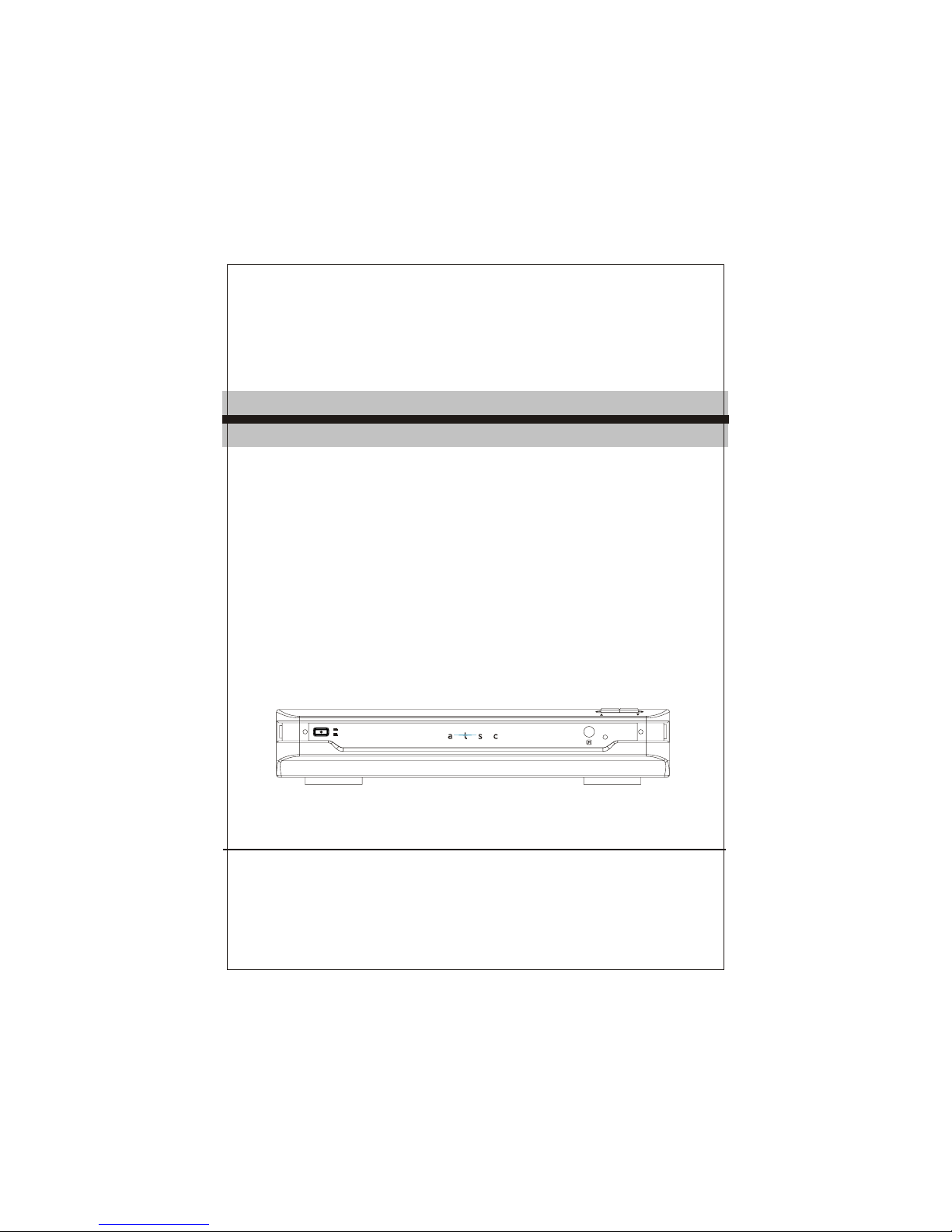
AT2016
ON
OFF
CHANNEL
Please read thisUser Manual carefullyto ensure properuse of thisproduct and
keep this manualfor future reference.
USER MANUAL
ATSC CONVERTER BOX
AT2016

Table of Contents
Important Safety Instructions....................................................................1
1. Introduction.........................................................................................4
1.1 Remotecontrol ..................................................................................5
1.1.1 Installingthe batteries......................................................................6
1.1.2 Usingthe remote control ..................................................................6
1.2 Front Panel and Rear Panel Illustration ............................................... 7
1.2.1 FrontPanel.....................................................................................7
1.2.2 RearPanel .....................................................................................7
1.3 Connecting yourAtsc Converter Box.................................................... 8
1.3.1 Connecting Antennas.......................................................................8
1.3.2 Connecting to aTV Set.....................................................................9
1.3.3 Connecting toan Audio System....................................................... 10
2.On-Screen Menus................................................................................11
2.1 Auto Program....................................................................................11
2.2 Manual Channel Set..........................................................................12
2.3 Password ........................................................................................ 12
2.4 Parental control................................................................................ 12
2.5 Advanced Closed Caption.................................................................. 13
2.6 Language......................................................................................... 14
2.7 Auto Power Down Timer.................................................................... 14
2.8 Smart Antenna.................................................................................. 14
3. Troubleshooting................................................................................ 15
4. Specifications ................................................................................... 16
5. Glossary............................................................................................ 17
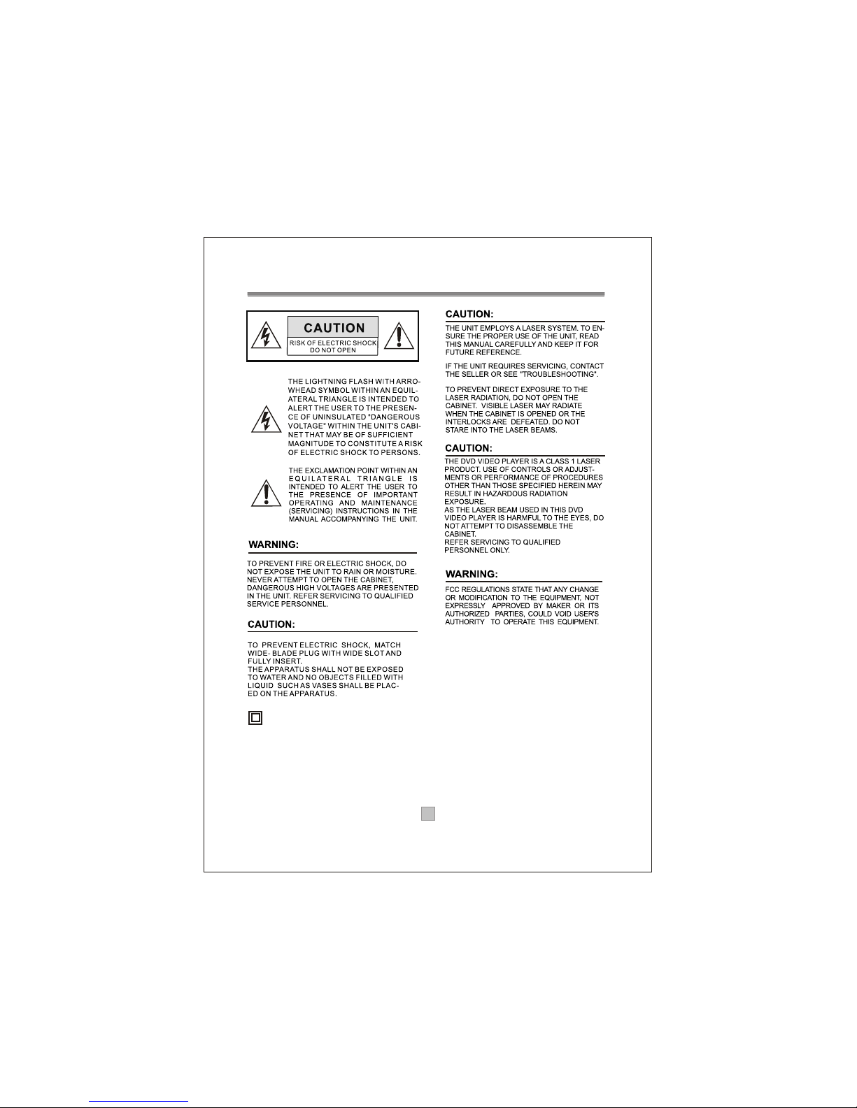
Important Safety Instructions
This symbol indicates that this product incorporates
double insulation between hazardous mains voltage
and user accessible parts. When servicing use only
identical replacement parts.
WARNING: To reduce the risk of fire or electric shock,
do not expose this apparatus to rain or cords.
1. The apparatus shall not be exposed to dripping
or Splashing and that no objects filled with liquids,
such as Vases, shall be placed the apparatus.
2. The mains plug is used as the disconnect device,
the disconnect device shall remain readily operable.
3. To be completely disconnect the power input,
the mains plug of apparatus shall be disconnected
from the mains.
4. The mains plug of apparatus should not be
obstructed or should be easily accessed during
intended use.
5. The battery (battery or batteries or battery pack)
shall not be exposed to excessive heat such as
sunshine, fire or the like.
1
1. Read these Instructions.
2. Keep these Instructions.
3. Heed all Warnings.
4. Follow all instructions.
5. Do not use this apparatus near water.
6.
7. Do not block any of the ventilation openings.Install in accordancewith the
manufacturers instructions.
8. Do not install near any heat sources suchas radiators, heatregisters, stoves,
or other apparatus(including amplifiers) that produce heat.
9. Do not defeat the safety purpose of thepolarized or grounding- type plug.
A polarizedplug has two blades with one wider than the other. A groundingtype
plug has twoblades and a third grounding prong. The wide blade or the third
prong are provided for your safety. When theprovided plug doesnot fit into your
outlet, consult anelectrician for replacement of the obsolete outlet.
10. Protect thepower cord from being walked on or pinched particularly at plugs,
convenience receptacles, andthe point where they exit from the apparatus.
11. Onlyuse attachments/accessories specifiedby the manufacturer.
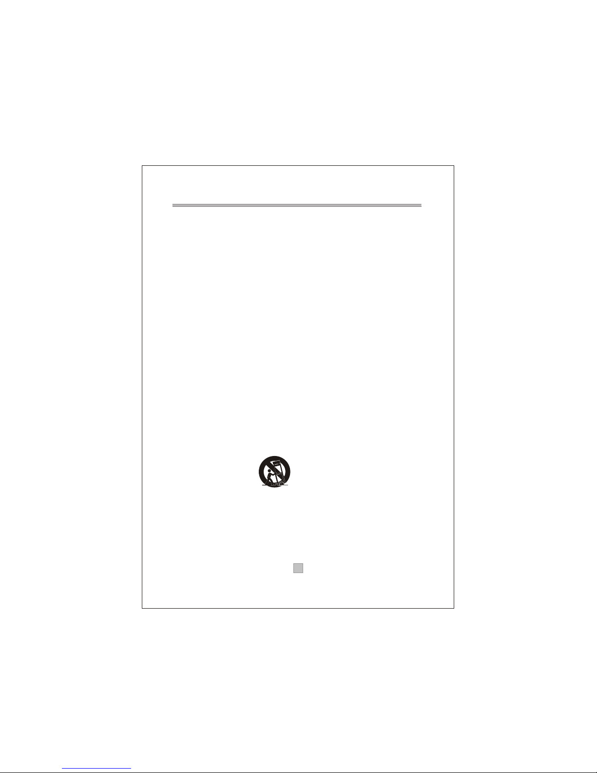
12. Use onlywith a cart, stand, tripod, bracket, or table specified by the
manufacturer, orsold with the apparatus. When a cart is used, use caution when
moving the cart/apparatuscombination to avoid injury from tip-over.
13. Unplug thisapparatus during lightning storms or when unused for long
periods of time.
14. Refer allservicing to qualified service personnel. Servicing is required when
the apparatus hasbeen damaged in any way,such as power-supply cord or plug
is damaged, liquidhas been spilled or objects have fallen into the apparatus,
the apparatus hasbeen exposed to rain or moisture , does not operate normally,
or has beendropped.
Clean only with dry cloth.
Portable Cart Warning
2

Note:
1. Important safetyinstructions shall beprovide will each appliance.
These safety instructionsmay be inthe form of a separate booklet, separate
sheet, or partof the instructionmanual.
2. If includedin the instructionmanual, the safety instructions shall be located
before any operatinginstructions. 3. Theseinstructions shall beentitled
IMPORTANTSAFETY INSTRUCTIONS .
4. The safetyinstructions shall include,as applicable tothe particular apparatus,
the information andwarnings listed before.The wording iscapable of being
supplements, although notreplaced, by drawingor cartoons.
5. The symbolshall be shownadjacent to thetext of ImportantSafety Instructions
Warning: Changes or modifications to this unit not expressly approved bythe
,
party responsible forcompliance could voidthe users authority to operate the
equipment.
NOTE: This equipmenthas been testedand found tocomply with thelimits for a
Class B digitaldevice, pursuant toPart 15 of the FCC Rules. These limits are
designed to providereasonable protection againstharmful interference in a
residential installation. Thisequipment generates, uses,and can radiateradio
frequency energy and, if not installed and used in accordance with the
instructions, may causeharmful interference toradio communications. However,
there is noguarantee that interferencewill not occur in a particular installation.
If this equipmentdoes cause harmfulinterference to radio or television reception,
which can bedetermined by turning the equipment offand on, theuser is
encouraged to tryto correct theinterference by one or more of the following
measures:
- Reorient or relocate the receiving antenna,
- Increase the separation between the equipment and receiver.
- Connect the equipment into an outlet on acircuit different fromthat to
which the receiveris connected.
- Consult the dealer or an experienced radio TV technician for help.
3
Table of contents


