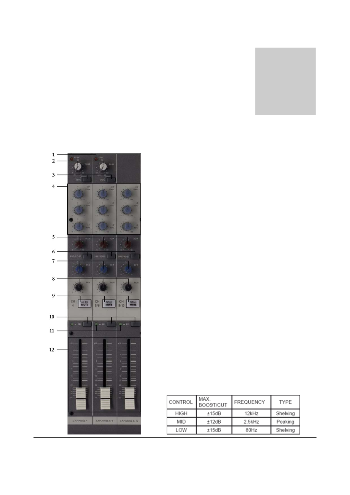
AUDAC PMX124 Installation and operating instructions

PROFESSIONAL AUDIO EQUIPMENT
PMX124 12 Channel mixing console
User Manual &
Installation Guide
Mixing Console
PMX124
AUDAC

AUDAC PROFESSIONAL AUDIO EQUIPMENT
User Manual & Installation Guide
AUDAC
http://www.audac.eu

2
INTRODUCTION.....................................................................................................................................................................................................................3
ENVIRONMENT......................................................................................................................................................................................................................4
SAFETY REQUIREMENTS...................................................................................................................................................................................................5
CAUTION –SERVICING......................................................................................................................................................................................................5
FRONT PANEL CONTROLS.................................................................................................................................................................................................6
CHANNEL CONTROL SECTION........................................................................................................................................................................................6
MAIN CONTROL SECTION.................................................................................................................................................................................................8
CONNECTIONS AND CONNECTORS..............................................................................................................................................................................11
FRONT PANEL CONNECTIONS.......................................................................................................................................................................................11
REAR PANEL CONNECTIONS .........................................................................................................................................................................................14
POINTS TO REMEMBER ...................................................................................................................................................................................................15
CONNECTIONS...................................................................................................................................................................................................................15
APPLICATIONS.....................................................................................................................................................................................................................17
SETUP PROCEDURE..........................................................................................................................................................................................................17
HOME RECORDING...........................................................................................................................................................................................................18
LIVE PERFORMANCE .......................................................................................................................................................................................................19
BLOCK DIAGRAM ...............................................................................................................................................................................................................20
ADDITIONAL INFORMATION..........................................................................................................................................................................................21
TECHNICAL SPECIFICATIONS .......................................................................................................................................................................................21
PERSONAL NOTES...............................................................................................................................................................................................................23
Index

3
Introduction
This section briefly describes the possibilities of the PMX124 Mixing Console.
he PMX124 Mixing Console was developed as an easy to use, flexible solution for
multifunctional use.
During the development of the PMX124, the AUDAC-engineers wanted to achieve four goals:
-Delivering a flexible audio solution to control multiple functions
-Easy to use
-Excellent sound quality
-Modern and advanced design
The AUDAC PMX124 is a 12 channel premium, high-headroom, easy to use analog mixer. It is
designed as a versatile mixer with all the necessary controls and connections to be applied in a wide
variation of applications, ranging from rehearsal rooms to home studio’s and even on stage use.
It has a modern design with various connection possibilities for all kinds of microphones and
music sources, while guaranteeing an excellent sound quality .
The mixer has also a built-in 24-bit DSP with 100 presets, including effects such as Chorus,
Flange, Delay, … and many others, allowing each mix or vocal to be tuned as desired.
In addition to this, all connections and controls required for connecting external effect modules
are also provided.
Main features:
4 Mono & 4 Stereo channels input
Stereo Main output & ALT 3/4 output.
AUX Return and 2 x AUX Send
3 Band Equalizer
PFL function for all channels
24bit DSP effect 100 presets, EFX on/off & EFX level
Tape with PFL switch, Headphone / Control Room
Foot switch connection
Phantom Power (+48V)
19” Brackets included
T

4
Environment
Do not place this unit in an enclosed environment such as a bookshelf or closet. Ensure
that there is adequate ventilation to cool the unit.
Do not place the unit in environments which contain high levels of dust, heat, moisture or
vibration.
Do not use the unit near water or other liquids. Make sure no water or other liquids can be
spilled, dripped or splashed on the unit.
This unit was developed for indoor use only. Do not use it outdoors.
Do not place objects on top of the unit.
Place the unit on a stable base or mount it in a stable 19” rack.
Chapte
r
1

5
Safety Requirements
Always handle the unit with care.
Only use a grounded socket outlet and a power cord with grounding plug to plug in the
unit.
This unit is not a toy. It should not be operated by children.
Do not stick objects through ventilation openings.
Do not open the unit (risk for electrical shock).
CAUTION – SERVICING
This unit contains no user serviceable parts. Refer all servicing to qualified
service personnel. Do not perform any servicing unless you are qualified to do
so.
Note
This product conforms to the following European Standards: EN 50081-1: 1992, EN
50082-1: 1992, EN 60065: 19

6
Front Panel Controls
Channel Control Section
1. Peak LED indicator:
These LED indicators light-up when the level of the input
signal reaches 5 dB below the channel’s clipping point. It
shows the level of the POST-EQ /PRE fader signal.
When it lights up frequently, the ‘Trim Control’
potentiometer has to be used to decrease the input
sensitivity of the channel. When this causes no
improvement, the output level of the connected source has
to be reduced.
2. Trim Control:
With this button, the level of the input signal can be
adjusted to an appropriate level. The best signal/noise and
dynamic range balance will be reached when you adjust the
‘Trim Control’ so that the ‘Peak LED indicator’ lights-up
occasionally. The input sensitivity of a Mic channel can be
set between -50 dB and -6 dB, the input sensitivity of a
Line input can be set between -30 dB and +14dB and the
sensitivity for a Mono/Stereo combination channel can be
set between -20 dB and +20 dB.
3. HPF (High Pass Filter):
This switch toggles the HPF ON and OFF. To turn the
HPF on, make sure the button is pushed-in. The HPF cuts
frequencies below 75Hz.
4. 3-Band equalizer controls:
This is a 3-band equalizer whose center frequencies, range
and type are shown in the table below. The frequency
response is flat when the knob is set in the ‘0’position.
Chapte
r
2

7
5. Aux controls:
The Aux knobs controls the level of the signals that are sent to the Aux bus.
6. PRE / POST switch:
This button determines whether the AUX signal is Pre Fader (signal level is not influenced by fader
position) or Post fader (signal level is influenced by fader position).
7. EFX controls:
These knobs control the level of the signals sent to EFX bus. The signals mixed by this bus are sent to
the EFX SEND jack located on the front, and the overall level of this bus can be set by the ‘Master
AFX Send Control’. Because of the control that is placed after the channel fader, the signal level will be
influenced by the channel’s fader setting.
NOTE: The EFX bus signal is also fed into the internal digital signal processor (DSP).
8. PAN / Balance control:
- PAN (Mono Channel): This control pans the channel signal across the master L and R outputs,
therefore determining the ideal position of the sound from that channel. When the PAN control is set
all the way to the left, the sound from that channel will only be heard from the left speaker. Same
situation for the control being set all the way to the right. When this control is set in intermediate
position, the sound will be played at both channels in a stereo sound application.
- BALANCE (Stereo Channel): This control adjusts the balance or the L/R position of the stereo
input signal. Turning the BALANCE control to the left of center moves the source signal towards the
MAIN MIX L bus, turning it to the right moves the source towards the MAIN MIX R bus.
9. Mute / ALT 3-4 switch:
When the ‘Mute / ALT3/4’ button is deactivated (depressed) the channel output will be sent to the
‘ALT3/4’ output and not to the ‘MAIN L/R’ output. The ‘ALT3/4’ bus gives you a second
independent stereo sub mix with its own sub master stereo fader.
10. PFL switch:
This button allows you to monitor the ‘Pre Fader Level’ input signal through a ‘Headphone’ or the
‘Control Room Outputs’. When the button is NOT pressed the channel signal will be sent to the PFL
bus.
11. PFL indicator:
This indicator lights-up when the PFL switch is turned on.
12. Channel fader:
These faders are the main level control for the corresponding channels. It determines the level of the
signal that is sent from the channel to the master mixing and effect busses. The settings of the faders
determine the mix, balance and sound levels between the instruments or other sources connected to
the inputs. When a channel is not used, it’s fader should be set at the minimum position to prevent the
addition of unwanted noise in the main program signal.

8
Main Control Section
1. DSP program display:
This display shows the program number of the
selected effects program.
2. DSP program select switch:
This program knob allows you to select one of
the 100 digital effects of the built-in 24 bit,
high quality, digital signal processor.
Some of these effects are Delay, Chorus and
Reverb.
3. AUX PRE control:
Use this control to adjust the signal level that is
sent from the internal digital effect to the AUX
bus.
4. DSP ON/OFF switch:
This switch allows you to turn the internal
digital effect ON and OFF.
5. PFL switch:
Pushing this button ‘in’ will send the effect
signal to the PFL bus.
6. PFL indicator:
This indicator lights-up when the PFL switch
is turned on.
7. EFX RTN fader:
With this fader, the signal level sent from the
digital effect to the MAIN bus can be adjusted.
8. ALT 3/4 output fader:
With this fader, you can adjust the final
combined stereo signal level that is sent to the
ALT 3/4 output jacks.
9. To main switch:
When this button is pressed ‘in’, the mixer will
send the signal from the ‘ALT 3/4' to the
‘MAIN L/R’ outputs.

9
10. Main L/R master fader:
This fader adjusts the final signal level sent to the ‘MAIN L/R’ output.
11. Level-Meter Signal Buttons:
Use these buttons to determine the signal that is sent to the ‘Control Room’ and/or ‘Headphone’
outputs. The illustration below shows how the button settings correspond to the signal selection.
12. Control room / Phones control:
This knob controls the level of the signal that is sent to the ‘Control Room’ Jacks or the ‘Headphone’
Jack.
13. Tape-IN control:
This knob controls the level of the playback signal that is connected to the ‘Tape-in’ RCA Jacks.
14. Master send:
- Master AUX Control:
Use this control knob to adjust the signal level sent to the ‘AUX’ output jack.
- Master EFX Control:
Use this control knob to adjust the signal level from the ‘Effect’ bus sent to the ‘Effect Output’ Jack.
15. PFL indicator:
This indicator lights-up when the PFL switch is turned on.
16. Output level meter:
A vertical row of ten LED’s continuously indicate the output level of the signal that is selected by the
‘Level Meter Signal Buttons’. The 0 LED indicates an output level of +4 dB.
When the LED bar lights up red, the signal is coming close to clipping level.
17. Stereo return control:
- AUX CONTROL:
Use this control knob to adjust the level of the signal sent from the ‘Return’ Jack to the ‘AUX’ bus.
- MAIN CONTROL:
Use this control knob to adjust the level of the signal sent from the ‘Return’ Jack to the ‘Main’ bus.
18. Power indicator:
This indicator lights-up when the power switch is turned on.

10
19. Phantom power switch:
Use this switch to toggle the phantom power ON and OFF. When the switch is turned ON, the mixer
supplies phantom power to all channels that contain XLR Mic input connectors. Turn this switch ON
when using one or more condenser microphones, however the switch may be left on when connecting
balanced dynamic microphones.
NOTE: When this switch is on, the mixer supplies +48V DC power to pins 2 and 3 of all XLR-type ‘Mic Input’
connectors. We also recommend to turn all output controls to minimum settings before operating the switch, to avoid the risk
of loud noises that could cause hearing loss or damage.
20. Phantom power indicator:
This indicator lights-up when the phantom power switch is turned on.

11
Connections and Connectors
Front panel connections
1. Channel input jacks:
- MIC JACKS:
3-pin XLR connectors are used for the connection of balanced low impedance microphones.
- BALANCED LINE IN JACKS:
Standard ¼ ” TRS (Tip, Ring, Sleeve) phone jacks are used for balanced or unbalanced line level
signals. Some examples of line level equipment include most electronic keyboards, synthesizers, turn-
tables(with appropriate preamps), tape decks and the line outputs from other mixers.
Chapter
3

12
2. Channel insert I/O jack:
These are ¼ " TRS (Tip, Ring, Sleeve) phone Jacks which support bi-directional operation. These
input/output jacks are located between the head-amplifier and the high pass filter. They can be used to
connect these channels independently to your own graphic equalizers, compressors, noise filters, or
other devices.
NOTE: Connection to an I/O Jack requires a special separately sold insertion cable. It is described in the illustration
below.
3. Channel input jacks:
These are unbalanced stereo line input jacks. There are two different types of jack’s provided, phone
type ¼ " TRS (Tip, Ring, Sleeve) Jacks and RCA pin type Jacks.
4. Stereo return L (mono), R jack:
These are unbalanced ¼ ” TRS (Tip, Ring, Sleeve) phone-type line input jacks. The signal received by
these jacks is sent to the ‘MAIN’ bus and ‘AUX’ bus. These jacks are typically used to receive a return
signal from an external effect (reverb, delay, etc.).
NOTE: These jacks can also be used as an auxiliary stereo input. If you connect to the L (MONO) jack only, the
mixer will recognize the signal as a mono signal and will propagate the identical signal on both L and R jacks.
5. Tape in jacks:
These RCA pin input jacks can be used to connect a stereo sound source. They are often used to
connect a CD or DAT player for direct monitoring.
NOTE: You can adjust the signal level using the ‘TAPE IN’ control knob in the Master control section.
6. Rec out jacks:
At the ‘REC OUT’ connectors is the pre-fader signal from the master bus available to be connected
with a recording device.
7. Send jacks:
- AUX:
This is an unbalanced phone type output jack on which the output signal of the AUX bus is available.
It can be used for connecting an effector, cue box or other monitoring system.
- EFX:
This is an unbalanced phone type output jack on which the output signal of the EFX bus is available.
It can be used for connecting an external effector.
8. Foot switch jack:
To this phone input jack, a foot switch can be connected. When a foot switch is connected, it can be
used to toggle the digital effects ON and OFF.

13
9. ALT 3/4 output jacks:
These are unbalanced ¼” phone type output jacks on which the output signal of the ALT 3/4 bus is
available. These jacks can be used to connect to the input jack of an MTR, external mixer or other such
device.
10. Main L/R output jacks:
On these jacks is the main stereo output signal available. These jacks can be used for connecting the
power amplifier which is used to drive your main speaker system. This signal can also be used when
recording the output signal influenced by the ‘Main fader’ level control in the ‘Master Control’ section.
The connections are made by TRS (Tip, Ring, Sleeve) phone-type balanced output jacks.
11. Control room output jacks:
These stereo ¼” phone-type output jacks can be used to send the mixed output signal to a monitoring
system. Use the ‘Control Room/Headphone Control’ to adjust the output signal level.
NOTE: The signal available on these jacks can be selected by the settings of the ‘Main-ALT3/4’ toggle switch, the
‘Tape In’ switch and the PFL switches on the input signals.
12. Phones jack:
This is a stereo phone-type output jack which can be used for connecting Headphones to the mixing
table.
NOTE: The signal available on this connector can be selected by the settings of the ‘Main-ALT3/4’ toggle switch, the
‘Tape In’ switch and the PFL switches on the input signal.

14
Connections and Connectors
Rear panel connections
1. AC adaptor in connector:
Connects to the included PA-M1224 power adaptor.
NOTE: Only use the original included PA-M1224 power adapter. The use of a different power adapter may cause
damage to the appliance, or can even cause fire or electrical shocks.
2. Power switch:
Use this switch to turn the mixer ON and OFF.
3. Main balanced L/R output:
The main stereo output signal of the mixer is available on these 3-pin balanced XLR connectors. They
can be used for connecting the main stereo output signal of the mixer to a power amplifier with
balanced signal inputs, which is used to drive your main speaker system.

15
Points to remember
In all cases, always use high quality twin screened audio cable. Check for instability at the output.
Always connect both conductors at both ends, and make sure that the shield is connected only at one
end.
Don’t disconnect the mains earth from each piece of equipment. This is needed to provide both safety
and screen returns to the system star point.
Equipment which has balanced in- and outputs may need to be electrically isolated from the equipment
rack and/or other equipment, to avoid earth loops.
It is important to remember that all equipment which is connected to the mains, is a potential source of
hum and interference and may radiate both electrostatic and electromagnetic radiation. In addition, the
mains will also act as a carrier for many forms of RF interference generated by electric motors, air-
conditioning units, light dimmers, etc. Unless the earth system is clean, all attempts to improve hum
noise levels will be ineffective. In extreme cases there will be no alternative but to provide a completely
separate and independent ‘technical earth’ to replace the incoming ‘noisy earth’. However, always
consult your local electricity supply authority to ensure that safety regulations are not being infringed.
Connections
The in- and output connections of AUDAC audio equipment are performed corresponding to
international wiring standards for professional audio equipment.
Balanced XLR connectors are wired
as described:
- Pin #1: Shield
- Pin #2: Positive
- Pin #3: Negative
Balanced ¼” TRS (Jack) connectors
are wired as described:
- Tip: Positive
- Ring: Negative
- Sleeve: Shield

16

17
Applications
Setup procedure
1. Before connecting the microphones and instruments, be sure that all devices are turned off. Also be
sure that all of the mixer’s channel faders and master control faders are set all the way down.
2. For each connection, connect one end of the cable to the relevant microphone or instrument, and
connect the other end to the appropriate input jack on the mixer.
NOTE: Where an input channel contains both a ‘Mic Input’ and a ‘Line Input’ jack, you may use either one of these
jack’s but don’t use both at the same time.
3. To avoid damage to the speakers, power-up the devices in the following order:
Peripheral devices Mixer Power amps (or powered speakers).
NOTE:
When shutting the system down, turn off the power in the opposite order:
Power amps (or powered speakers)
Mixer
Peripheral devices.
Chapte
r
4

18
Home Recording

19
Live Performance
Table of contents
Other AUDAC Music Mixer manuals