Audemo SYSTEMS Dante DPM-2500A User manual
1
©2023 by AUDEMO-SYSTEMS®, Schatzbogen 62, 81829 München V3
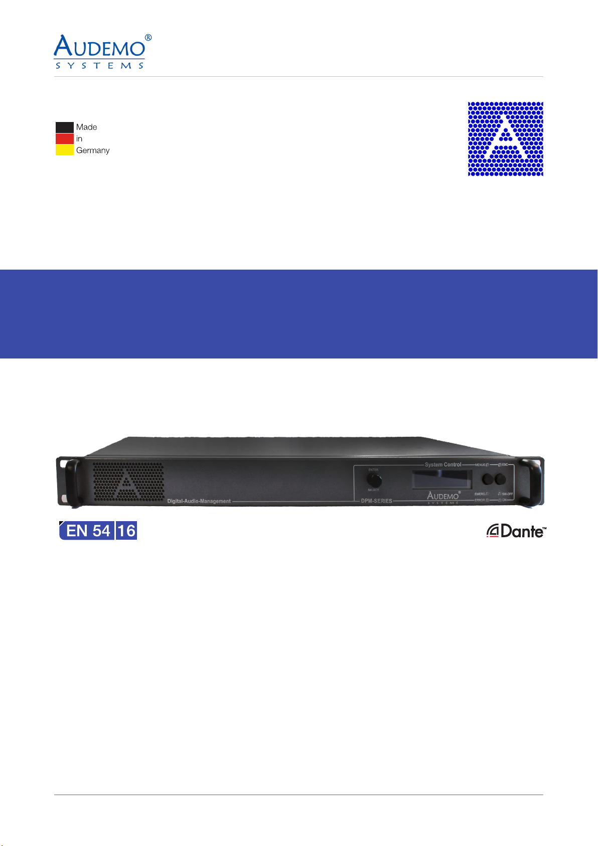
DPM-2500A
Digital-Audio-Matrix
USER MANUAL

2
©2023 by AUDEMO-SYSTEMS®, Schatzbogen 62, 81829 München V3
CONTENTS
1. General ------------------------------------------------------------------------------------------- 3
2. Safety Instructions ------------------------------------------------------------------------------- 4
3. Technical Features ------------------------------------------------------------------------------- 6
4. Operational Controls ----------------------------------------------------------------------------- 7
5. Programming DPM 2500x (digital paging module) -------------------------------------- 9
6. Setting up speaker lines (Speaker Line) --------------------------------------------------- 10
6.1) DMS-2021A ------------------------------------------------------------------------------- 10
6.2) DMS-2061A ------------------------------------------------------------------------------- 11
6.3) DMS-2068A ------------------------------------------------------------------------------- 12
6.4) DAA-235XX -------------------------------------------------------------------------------- 13
6.5) DAA-236XX ------------------------------------------------------------------------------- 14
6.6) DAA-237XX ------------------------------------------------------------------------------- 15
7. Setting up line groups (Line Group) -------------------------------------------------------- 16
7.1) DMS-2021A ------------------------------------------------------------------------------ 16
8. Installing the Controller -------------------------------------------------------------------------17
9. Connections and additional Possibilities ---------------------------------------------------18
9.1) Connection of loudspeaker lines --------------------------------------------------- 18
10. Options --------------------------------------------------------------------------------------------18
11. Technical Specifications -----------------------------------------------------------------------19
12. Environment Protection -----------------------------------------------------------------------19

3
©2023 by AUDEMO-SYSTEMS®, Schatzbogen 62, 81829 München V3
This operation manual includes important notes on safe operation of the unit. Please read all instructions
and safety regulations. Keep these instructions for future reference. Take care that the operation manual is
available to all users.
Our products are subject to continuous development. Therefore, any technical modication subject to change
without notice.
Symbols and Important Notes
This section provides you with an overview of safety warnings and symbols and their importance.
1. General
Safety Warning Importance
DANGER! Warning of a possible danger, which can lead to death or to serious injuries, if
not avoided.
CAUTION! Warning of a possible danger, which can lead to a possibly dangerous situation,
if not avoided.
Warning Symbol Type of risk
Caution! Warning of a possible danger!
Caution! Risk of electric shock!

4
©2023 by AUDEMO-SYSTEMS®, Schatzbogen 62, 81829 München V3
1. Please read all instructions before operating the unit.
2. Keep these instructions for future reference.
3. Follow manufacturer’s instructions.
4. Pay attention to all warnings. Do not remove any safety instruction or other information from the unit.
5. Use the unit only in the intended way.
6. Take note of applicable safety regulations.
7. CAUTION! Select the assembly site in such a way that the unit can be suciently cooled. Take care of
the details of the brief instructions.
8. CAUTION! Do not block vents.
9. CAUTION! Keep away ammable materials, liquids and gases.
10. CAUTION! Do not use this unit near water or moisture. Take care that no liquid penetrates into the
unit.
11. The installation must be carried out only with accessories recommended by AUDEMO SYSTEMS®. All
options could only be assembled ex works in terms of warranty.
12. CAUTION! Do not open or modify the unit.
13. Opening of the security protected united for servicing, repair and so on is only allowed by the service
department of AUDEMO SYSTEMS®. Interventions to the unit and breaking the seals will invalidate the
warranty agreement!
14. Opening of the unit deactivates all functions! For reactivating in factory a fee will be charged!
15. CAUTION! Always take care about all connections and cables after installation to avoid damages and
accidents with e.g. trip hazards.
16. DANGER! Pay highest attention while transporting that the system could never drop down or fall over
and causes injuries and material damage.
17. CAUTION! In any case of acute malfunction of the unit, damage or impact of objects or uids, switch o
the unit immediately and disconnect mains and emergency power supply. The unit as well as the system
could only be repaired or changed by the specialized company, the contracted maintenance company
or the manufacturer.
18. Clean the surface of the unit with a soft cotton cloth.
19. Pay attention to actual waste disposal laws and regulations
2. Safety Instructions

5
©2023 by AUDEMO-SYSTEMS®, Schatzbogen 62, 81829 München V3
DANGER!
Risk of electric shock of dangerous voltage within the units
enclosure
Within the units enclosure there are uninsulated parts with high electric tension.
Do not remove the cover. There are no user serviceable parts inside.
DANGER!
Risk of electric shock by short circuit
Always use properly earthed mains connections. Do not manipulate any cable
or cable connector. Noncompliance could lead to electric shock with danger of
serious injuries, death and re! If you are not sure please contact the specialized
company, the contracted maintenance company or the manufacturer
DANGER!
Possible Hearing Damage
The system produces a volume level which could damage your hearing
continuously or temporarily while listening to long to headphone or loud speaker
sound sources.
Do not reproduce high volume levels for a long time. Reduce the level immediately
if any noise in ear or hearing loss occurs.
Note: The level of the alert announcement may not be changed!
CAUTION!
Operating Conditions
The unit is intended for indoor use. To prevent damage do not use this unit near
liquids and moisture. Avoid direct sunlight, heavy dirt or strong vibration.
CAUTION!
Power Supply
Verify the mains connection before installation of the unit. Compare local
conditions with the information of the schematic diagram.
Initial operation, maintenance and servicing could only be aected by the
specialized company, the contracted maintenance company or the manufacturer.

6
©2023 by AUDEMO-SYSTEMS®, Schatzbogen 62, 81829 München V3
The Digital Paging Management Unit DPM-2500 A is a digital signaling audio control unit used to initiate/
manage live paging, audio signal routing and playing pre-recorded audio messages. The unit is ideal for
dierent audio applications including the voice alarm, mass notication (general alarm), background music
and professional public address. It is equipped with an internal monitoring of all alarm-relevant parts, internal
error logging and permanent monitoring of all PADES® 2000 system buses as well as the audio signal path
from the signal source to the loudspeaker line in accordance with the standard requirements of VDE 0828
and EN54 Part 16. The DPM-2500A is equipped with 4 independent (DSP-based) audio input channels. On the
output side, you can use four independent preamplier outputs for DPM -2500 A and DPM-2500B versions.
The digital paging management unit is used in combination with DAA ampliers and DMS-2021A to power
multi-independent loudspeaker outputs supporting class A or class A/B wiring.
Up to ten digital selective remote microphone units DPM- 2550 A or DPM-2550 B can be operated with each
DPM unit. If a DAM-2550 A system call station is to be connected to the paging management unit, this can be
done over TCP/ IP media or RS 485.
The unit can be equipped with a digital Dante-enabled card, model number DMS -2034A. For more details:
Review the user manual for DMS-2034A.
The audio signal processing allows the simultaneous operation of 4 independent speech paths in connection
with a supplementary software license. With the digital-analog input module, up to 4 monitored digital or
analog inputs are available. In order to play a selected input channel with priority, the NF-Digital-1-Channel-
Priority-Control-Module is used. Furthermore, an NF-Digital External Volume Control Module allows remote
volume control of a selected input channel. On the input side, there are high-performance audio AD
converters with 128x oversampling and input channel gain adjustable in 6 dB steps (0 – 42 dB), and on
the output side with high-performance audio DA converter with 128x oversampling and switchable output
channel gain (0/6 dB) is available. For a professional, unadulterated reproduction of speech and music, each
input/output features a ve-band parametric equalizer. Each audio input could be congured as a Line or Mic
input supporting phantom power input.
The below list describes the control ability of the system :
For warranty reasons, all options can only be installed in the factory. All system components are delivered
exclusively project related. A purchase of individual components is unfortunately not possible.
3. Technical Features
Number of Loudspeakers- Lines 1000
Number of Lines -Groups 1024
Number of Clock Events 8192
Number of Trigger Events 1024
Number of Events and Fault Logs 2047
Number of Priorities 255 x 255
Number of Signal Chain Entries 512
Number of Remote Paging Microphones DAM-2550A 64
Number of Remote Paging Microphones DPM-2550 A 32
7
©2023 by AUDEMO-SYSTEMS®, Schatzbogen 62, 81829 München V3
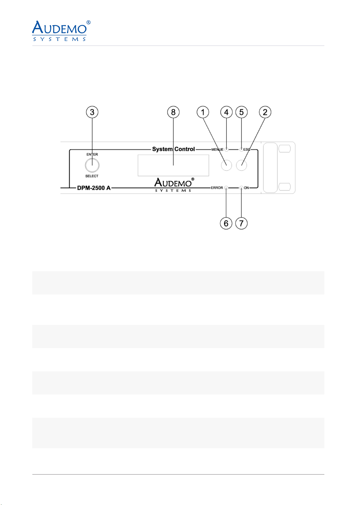
Front Panel:
4. Operational Controls
1Function Key MENU
Push the key to enter the next submenu.
2Function Key ESC
Push the key to leave the submenu to the next higher operating level.
3
SELECT-Turning Encoder with ENTER-Key Function
Rotate the encoder to change the menu items. The menu driven handling is indicated on the integrated
LCD-display. Push the encoder to conrmed a menu item (ENTER).
4MENU LED
The green LED MENUE is illuminated on selection of a submenu.
5ESC LED
The green LED ESC is illuminated on the possibility to leave a submenu to the next (higher) operating level.
6ERROR LED
The yellow LED ERROR is illuminated on each failure of the unit.
7ON LED
The green LED ON is illuminated on standby of the unit.
8
LCD-Display
Display with changing colour in order to indicate an error status of the unit. The display is illuminated yel-
low if any failure occurs.
8
©2023 by AUDEMO-SYSTEMS®, Schatzbogen 62, 81829 München V3
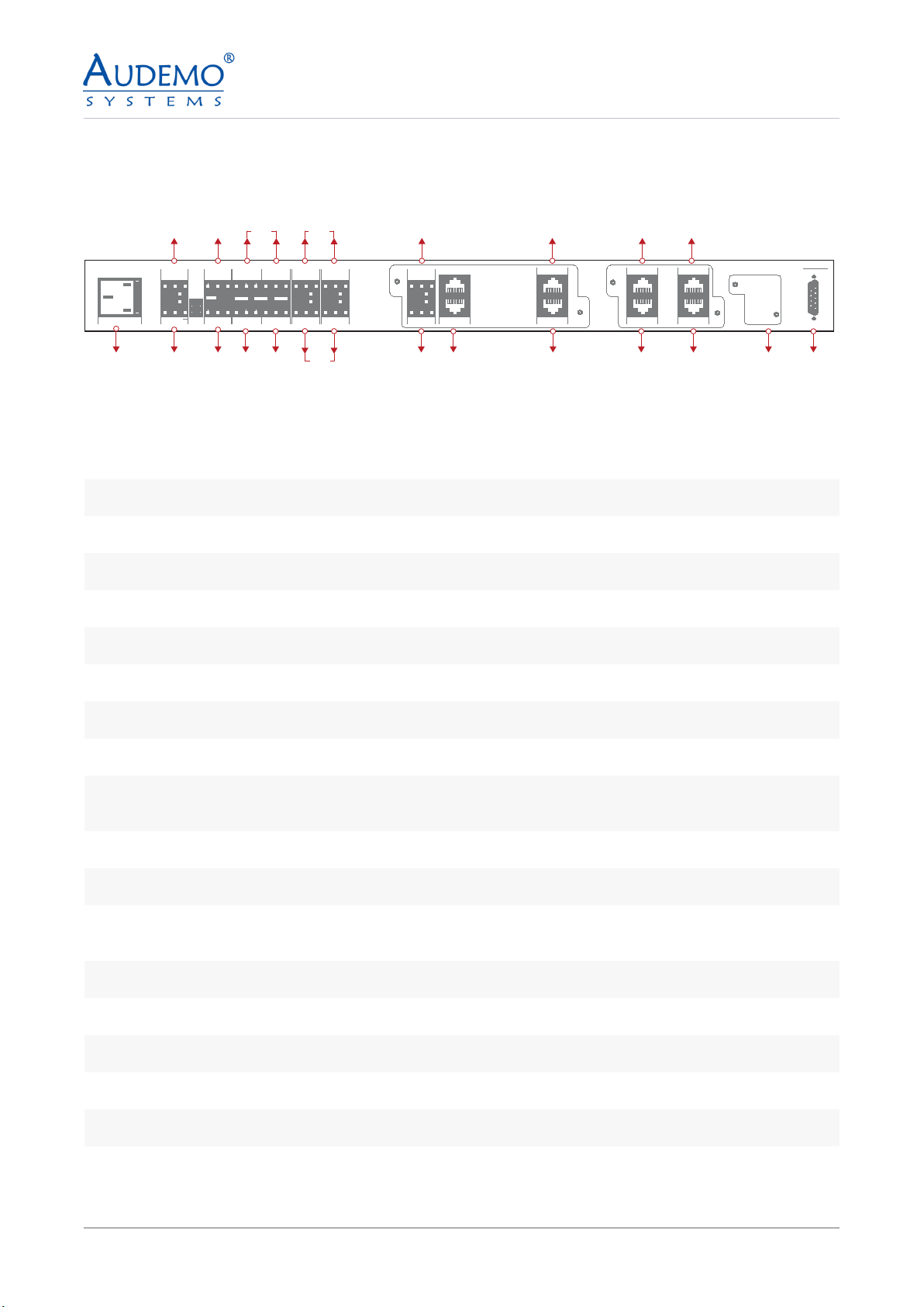
Rear Panel:
01 02
03
AC 230V FUSE 13.15A PF
-
24V
+
DPM-2500M AUDEMO
S Y S T E M S
®
RS-232
SPDIF IN
+-
REM-SWITCH
IN 1
IN 2
IN 3
IN 4
IN 5
COM
REL 1 REL 2
NC
COM
COM
NO
NC
NO
+24V SIG GND
DCF-77
GND
LIFT
ERROR
NO COM NC
SHLD
MIC 3
+-
SHLD
MIC 5
+-
SHLD
MIC 3 MIC 4
+-SHLD +-SHLD
EMERG-MIC 2
EMERG-MIC 1
REM-MIC
NETW.
NF OUT 2
+-SHLD
+-SHLD
NF OUT 1 IO-MOD
04
04 09 12 14 16
06 07 09 10 11 13 15 17 18
05 08
08
1240AC 50/60Hz MAIN POWER SUPPLY
2+24VDC SECONDARY POWER SUPPLY
3SPDF IN
4PROGRAMMABLE CONTROL INPUTS(5 INPUTS-NO/NC)
5PROGRAMMABLE RELAY OUTPUTS
6GPS PORT
7ERROR OUTPUT
8PROGRAMMABLE LINE/MIC INPUTS
9PROGRAMMABLE LINE OUTPUTS
10 IO-MOD(2 Nos):CONTROL THE DAM-2525 AND DAA-237X RANGE OF AMP+CONTROL AND POWER
FOR(DMS-2021A+DMS-2022A)
11 PRIMARY DANTE PORT(DMS-2034A)
12 SECONDARY DANTE PORT(DMS-2034A)
13 WALL MOUNT MICROPHONE (PRIMARY PORT TO DRIVE DAISY CHAIN OF REMOTE PAGING MICRO-
PHONES)
14 SECONDARY PORT TO DRIVE DAISY CHAIN OF REMOTE PAGING MICROPHONES
15 ETHERNET PORT (INTEGRATION WITH MODBUS)
16 THIRD PORT TO DRIVE REMOTE PAGING MICROPHONES OR TO DRIVE PoE MICROPHONES
17 PROVISION TO DRIVE PERIPHERAL DEVICES LIKE DPA 2274A /B AND DMS-2041A
18 SERIAL LINK FOR PROGRAMMING
DPM-2500 A
9
©2023 by AUDEMO-SYSTEMS®, Schatzbogen 62, 81829 München V3
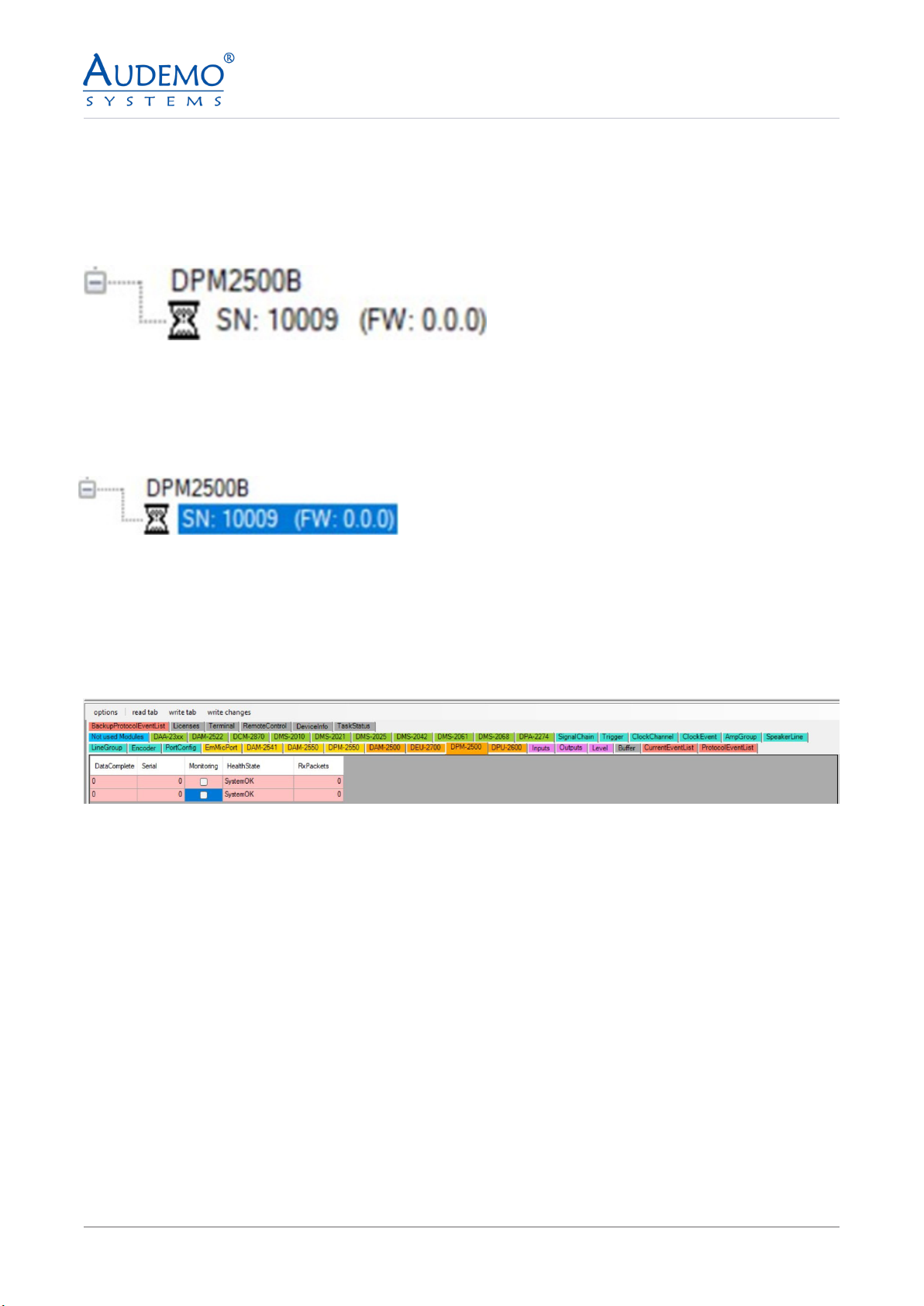
The programming is dierent depending on the internally installed or externally connected modules.
Overview in the Pades2000 Cong Tool
Note: DPM2500 will appear always as DPM-2500B even for DPM-2500A. Serial number will dene the version
5.1) Highlight the serial number under the device displayed
Now you will see the following in the main window:
5.2) Select the device you want to congure in the Cong Tool. In this case click on the TAB DPM-2500.
Example gure: Tree View Tab
Example gure: main window with selected TAB “DPM-2500”
Example gure: Tree view tab with serial number marked
5. Programming DPM 2500x (digital paging module)
10
©2023 by AUDEMO-SYSTEMS®, Schatzbogen 62, 81829 München V3
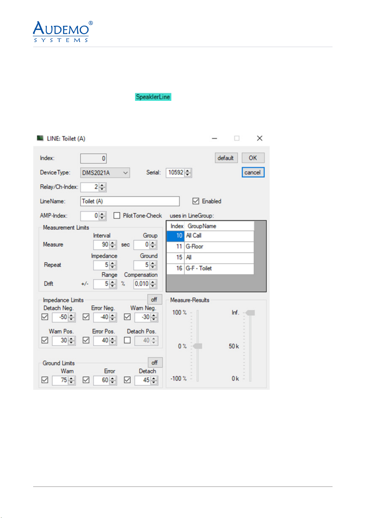
6.1) DMS-2021A
• Click on the TAB SpeakerLine -
• Double click on the rst free row in the main window.
• The following window appears:
• Look for your device under Device Type. In this case DMS-2021A
• Enter a serial number if it was not recognized by the system.
• For Relay/Ch-Index, enter the position on the relay to which this line is connected
• Give the line a unique name for “Line Name”.
• Enter the index number of your amplier under AMP index
6. Setting up speaker lines (Speaker Line)
11
©2023 by AUDEMO-SYSTEMS®, Schatzbogen 62, 81829 München V3
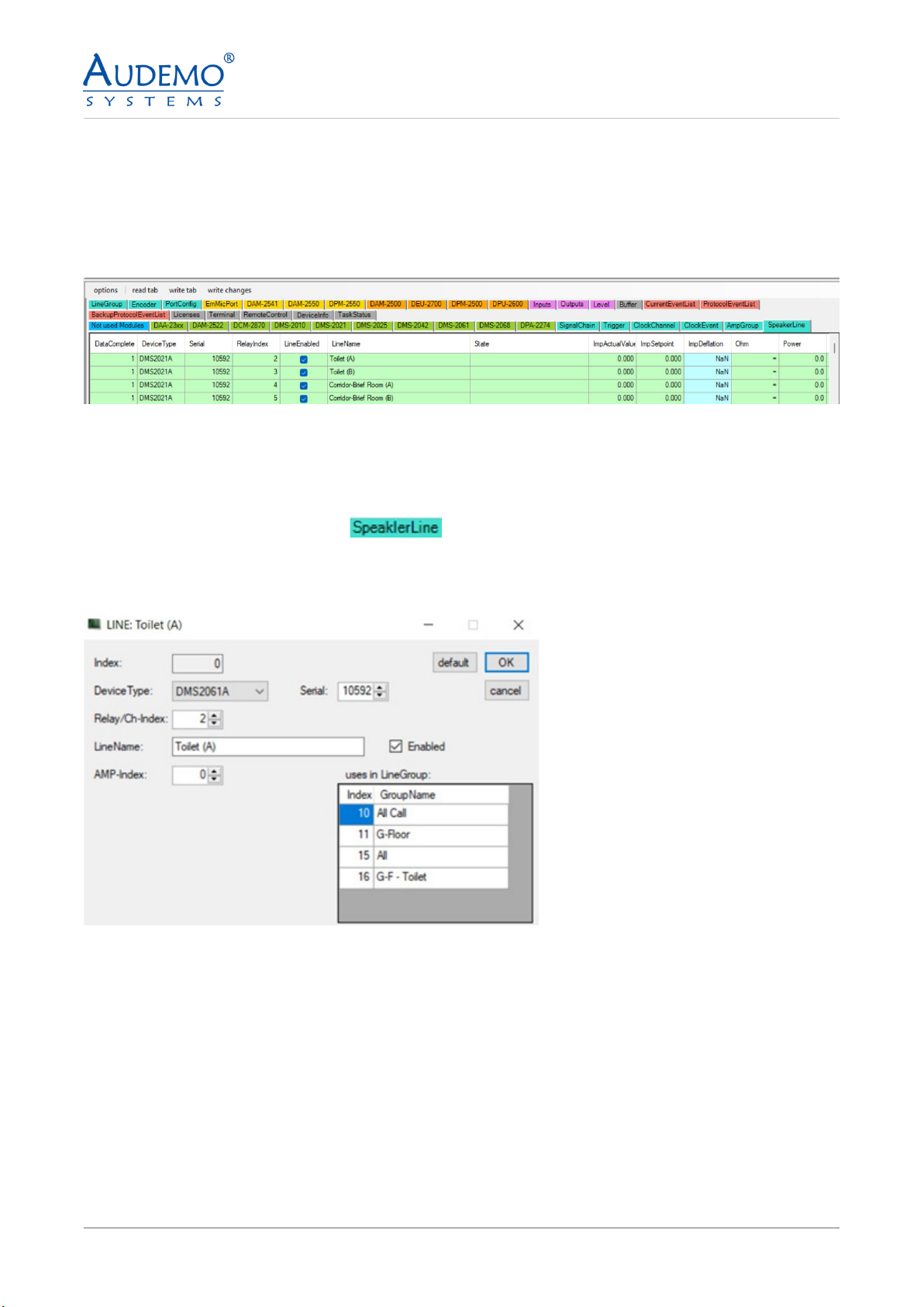
6.2) DMS-2061A
• Click on the TAB SpeakerLine -
• Double click on the rst free row in the main window.
• The following window appears:
• Look for your device under Device Type. In this case DMS-2061A
• Enter a serial number if it was not recognized by the system.
• For Relay/Ch-Index, enter the position on the relay to which this line is connected
• Give the line a unique name for “Line Name”.
• Enter the index number of your amplier under AMP index
• Check “Enabled” to activate the line you have congured.
• Note: The “uses in LineGroup” display does not show any line groups when speaker lines are set up for
the rst time. This only lls up when you have created line groups, see point 7.
• Click OK to apply your settings.
• Check “Enabled” to activate the line you have congured.
• Note: The “uses in LineGroup” display does not show any line groups when speaker lines are set up for
the rst time. This only lls up when you have created line groups, see point 7.
• Click OK to apply your settings.
Example image: After setting up several speaker lines
Note: Repeat the process as described in point 6.1 until you have set up all your speaker lines.
12
©2023 by AUDEMO-SYSTEMS®, Schatzbogen 62, 81829 München V3
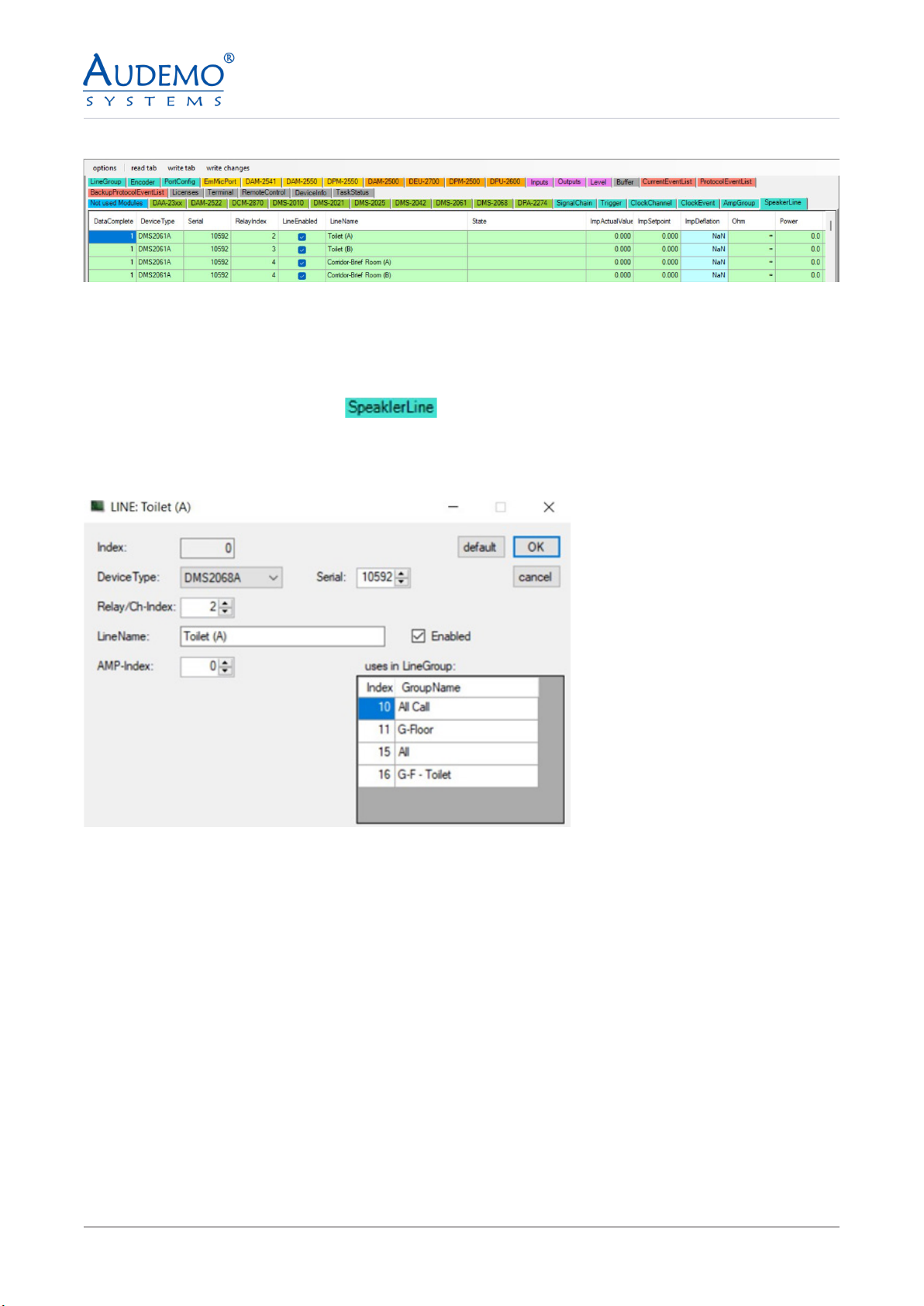
Example image: After setting up several speaker lines
Note: Repeat the process as described in point 6.2 until you have set up all your speaker lines.
6.3) DMS-2068A
• Click on the TAB SpeakerLine -
• Double click on the rst free row in the main window.
• The following window appears:
• Enter a serial number if it was not recognized by the system.
• For Relay/Ch-Index, enter the position on the relay to which this line is connected
• Give the line a unique name for “Line Name”.
• Enter the index number of your amplier under AMP index
• Check “Enabled” to activate the line you have congured.
• Note: The “uses in LineGroup” display does not show any line groups when speaker lines are set up for
the rst time. This only lls up when you have created line groups, see point 7.
• Click OK to apply your settings.

13
©2023 by AUDEMO-SYSTEMS®, Schatzbogen 62, 81829 München V3
Example image: After setting up several speaker lines
Note: Repeat the process as described in point 6.3 until you have set up all your speaker lines.
6.4) DAA-235XX
• Click on the TAB SpeakerLine -
• Double click on the rst free row in the main window.
• The following window appears:
• Look for your device under Device Type. In this case DAA-235XX
• Enter a serial number if it was not recognized by the system.
• For Relay/Ch-Index, enter the position on the relay to which this line is connected
• Give the line a unique name for “Line Name”.
• Enter the index number of your amplier under AMP index
• Check “Enabled” to activate the line you have congured.
Note: The “uses in LineGroup” display does not show any line groups when speaker lines are set up for the
rst time. This only lls up when you have created line groups, see point 7.

14
©2023 by AUDEMO-SYSTEMS®, Schatzbogen 62, 81829 München V3
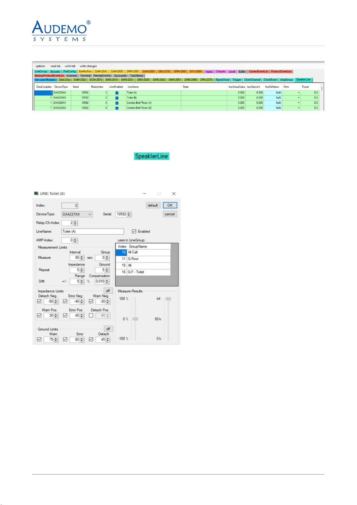
Example image: After setting up several speaker lines
Note: Repeat the process as described in point 6.4 until you have set up all your speaker lines.
6.5) DAA-236XX
• Click on the TAB Speaker Line -
• Double click on the rst free row in the main window.
• The following window appears:
• Look for your device under Device Type. In this case DAA-236XX
• Enter a serial number if it was not recognized by the system.
• For Relay/Ch-Index, enter the position on the relay to which this line is connected
• Give the line a unique name for “Line Name”.
• Enter the index number of your amplier under AMP index
• Check “Enabled” to activate the line you have congured.
• Note: The “uses in LineGroup” display does not show any line groups when speaker lines are set up for
the rst time. This only lls up when you have created line groups, see point 7.
• Click OK to apply your settings.
15
©2023 by AUDEMO-SYSTEMS®, Schatzbogen 62, 81829 München V3
Example image: After setting up several speaker lines
Note: Repeat the process as described in point 6.5 until you have set up all your speaker lines.
6.6) DAA-237XX
• Click on the TAB Speaker Line -
• Double click on the rst free row in the main window.
• The following window appears:
• Look for your device under Device Type. In this case DAA-237XX
• Enter a serial number if it was not recognized by the system.
• For Relay/Ch-Index, enter the position on the relay to which this line is connected
• Give the line a unique name for “Line Name”.
• Enter the index number of your amplier under AMP index
• Check “Enabled” to activate the line you have congured.
• Note: The “uses in LineGroup” display does not show any line groups when speaker lines are set up for
the rst time. This only lls up when you have created line groups, see point 7.
• Click OK to apply your settings.

16
©2023 by AUDEMO-SYSTEMS®, Schatzbogen 62, 81829 München V3
Example image: After setting up several speaker lines
Note: Repeat the process as described in point 6.6 until you have set up all your speaker lines.
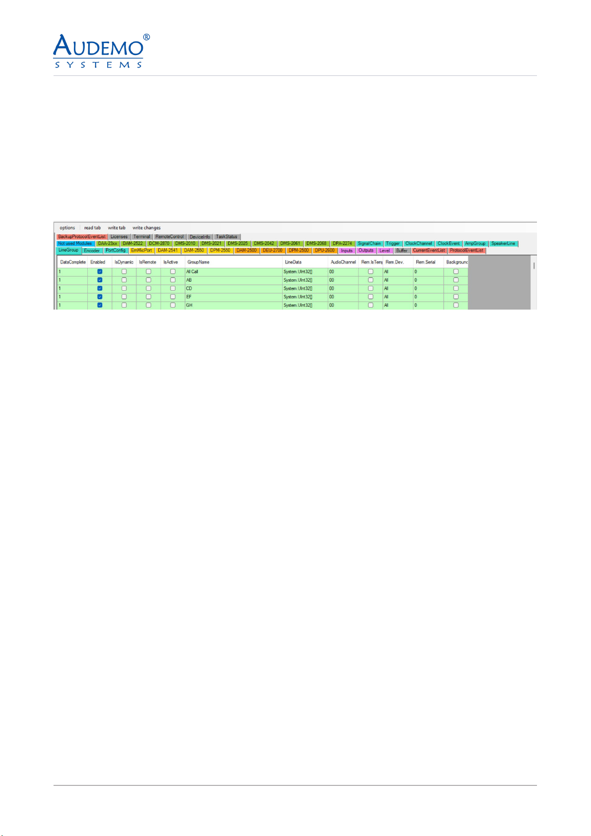
7. Setting up line groups (Line Group)
7.1) DMS-2021A
Here you have the option of grouping together the individual speaker lines that you set up under point 6,
for example to play announcements or background music throughout or in parts of the building.
• Click on the TAB Line Group -
• Double click on the rst free row in the main window.
• The following window appears:
Example illustration: Here you can see the loudspeaker lines congured under point 6.1
17
©2023 by AUDEMO-SYSTEMS®, Schatzbogen 62, 81829 München V3
Example image: After setting up a line group
Note: Repeat this process, as described under Point 7.1, until you have grouped all the speaker lines you want.
• Click on “Enabled” so that your group, which you are now dening, becomes active
• Give your group a unique name in “GroupName”. This is important so that you can later assign your
groups accordingly. Example: “All Call” for All speaker lines if they select all
• Select the lines you want.
• When you have made your settings, click on “OK”. These are then adopted by the system.
8. Installing the Controller
Unpacking
Unpack your controller and inspect for any damage that may have occurred during transit.
If damage is found, notify the shipping company immediately. Only you can initiate a claim for shipping
damage, though AUDEMO-SYSTEMS® will be happy to help as needed. If the product arrived, showing signs
of damage, save the shipping carton for the shipper’s inspection.
We also recommend that you save all packing materials for use if you ever need to transport the unit. Never
ship the unit without the factory carton and packing materials.

18
©2023 by AUDEMO-SYSTEMS®, Schatzbogen 62, 81829 München V3
9. Connections and additional Possibilities
9.1) Connection of loudspeaker lines
Take care for correct phase relation when you connect any loudspeaker.
Danger! Beware of short circuits and earth fault.
Adjust each speaker with the preset power as noticed in the cabling diagram. Test each single loudspeaker
line by a measurement of line impedance at 1000 Hz (Z-Meter with tone-signal) with exact protocolling of the
result.
10. Options
All options could only be assembled ex works. All components of the electroacoustic system could only be
delivered referring to a project. Unfortunately, there is no possibility of buying single components.
Order number Description Max. extension per unit
DPM-2500A Digital-Audio- Paging-Controller
DPM-2500B Digital-Audio -Paging- Controller
19
©2023 by AUDEMO-SYSTEMS®, Schatzbogen 62, 81829 München V3
11. Technical Specications
12. Environment Protection
Frequency range 20- 20000Hz
Gain Control -42 dB
Signal-to-noise ratio >92 dB
Harmonic distortion < 0.01 %
DSP resolution 32 bit
Dynamic range ( DSP ) 192 dB
D/A converter – resolution 24 bit
Dynamic range ( D/A converter) 118 dB
A/D converter – resolution 24 bit
Dynamic range ( A/D converter) 106 dB
Output voltage 220-240 V AC, 50 /60Hz
Emergency Power 24 VDC
Dimensions (W × D × H) 483 × 44 × 300 mm (1U)
Weight 4.7 kg
Protection rating IP30
Temperature range (operation) -5 to +55°C
In any case of replacement, the substituted unit is taken back from the manufac-
turer.
This product is subjected to European directive 2002/96/EG and 2012/19/EU
(WEEE-directive). Dispose this product never with your domestic waste.
Dispose a control center system with an accredited waste disposal company or
your
local disposal facility. Take care of applicable regulations. In case of doubt please
contact your local disposal facility.
User Manual DPM-2500A Version 01052023
Table of contents


 operating instructions")


