Primova MIDX-20 User manual

MIDX-20 User’s Manual 1
MIDX-20
DUAL USB MIDI Host
Class Compliant USB MIDI devi es
Roland/BOSS devi es
BOSS Katana Amplifiers
Fender Mustang™ Amplifiers
USER’S MANUAL
Rev. 2016-11-23

MIDX-20 User’s Manual 2
TableofContents
DESCRIPTION ............................................................................................................................. 3
CONNECTORS ............................................................................................................................ 4
MIDI IN AND MIDI OUT 5-PIN CONNECTORS ............................................................................ 4
USB CONNECTORS ..................................................................................................................... 4
POWER CONNECTORS ............................................................................................................... 5
PHYSICAL DIMENSIONS ............................................................................................................. 5
CONTROLLER JACKS 1 & 2 ......................................................................................................... 6
STATUS LEDS .............................................................................................................................. 7
Fender Mustang™ Bridge .......................................................................................................... 7
Fender Mustang™ Bridge - MIDI Implementation .................................................................... 8
SETTING UP THE UNIT ............................................................................................................. 10
MIDX-20 CONNECTION EXAMPLES.......................................................................................... 16
REAL-TIME MESSAGES ............................................................................................................. 18
MIDX-20 MODES / MIDI DATA FLOW ...................................................................................... 18
UPR IS ‘DEV OUT’ and MIDI THRU/MERGE is ‘OFF’ ............................................................. 19
UPR IS ‘DEV OUT’ and MIDI THRU/MERGE is ‘ON’ .............................................................. 19
UPR IS ‘DEV IN/OUT’ and MIDI THRU/MERGE is ‘OFF’ ........................................................ 20
UPR IS ‘DEV IN/OUT’ and MIDI THRU/MERGE is ‘ON’ ......................................................... 20
UPR IS ‘CTRL IN’ and MIDI THRU/MERGE is ‘OFF’ ............................................................... 21
UPR IS ‘CTRL IN’ and MIDI THRU/MERGE is ‘ON’ ................................................................ 21
UPR IS ‘CTRL IN/OUT’ and MIDI THRU/MERGE is ‘OFF’....................................................... 22
UPR IS ‘CTRL IN/OUT’ and MIDI THRU/MERGE is ‘ON’ ........................................................ 22
SETUP USING PC SOFTWARE ................................................................................................... 23
FIRMWARE UPGRADES ............................................................................................................ 23
WARRANTY .............................................................................................................................. 23

MIDX-20 User’s Manual 3
MIDX-20 DUAL USB Host
DESCRIPTION
The MIDX-20 unit has two USB Host ports (USB A so kets), a MIDI IN and a MIDI
OUT (both 5 pin MIDI) port, plus two controller jacks for generating MIDI from
external expression pedals or dual foot swit hes.
There are various pro rammable MIDI routin possibilities between the onne tors.
A USB MIDI (foot) ontroller may ontrol a USB devi e as well as other 5-pin MIDI
equipment.
Another routing possibility is when a 5-pin MIDI (foot) ontroller ontrols up to two
USB devi es (see separate hapter for full des ription of the routing apabilities).
When onne ting a guitar synthesizer with Guitar-to-MIDI onversion an external
synthesizer an be used for playba k.
The unit also has an optional MIDI THRU/MERGE mode, sending 5-pin MIDI IN to the
5-pin MIDI OUT at the same time as other data from the USB devi es is transmitted.
The two USB onne tors are fully Roland/Boss compatible allowing any Roland/Boss
USB devi e to be onne ted for ontrol or playba k. Roland/Boss devi es use a
vendor-spe ifi USB MIDI ommuni ation proto ol. This unit is ompatible with the
following Roland/BOSS Guitar devi es: Katana Amplifiers, GT-10, GT-100, GT-001,
VG-99, GR-55, GP-10 and SY-300.
Both USB onne tors re ognize Fender Mustan ™ Amplifiers allowing the amps to
be ontrolled using MIDI ommands (see the Mustang MIDI implementation hart
elsewhere in this manual).
Any MIDI class compliant USB device may be used with the unit, su h as Fishman
TriplePlay, KMM SoftStep2, Logidy UMI3 USB MIDI Foot Controller, et .
The MIDI USB Host is powered by a regulated 8-12V ( enter negative) mains adaptor
(not supplied) or a 5V Mini USB able via a phone harger (not supplied).
Important:
- The MIDX-20 does NOT support USB Hubs.
- Powering the unit using a Mini USB able dire tly onne ted to a Personal
Computer works, but is not re ommended as digital noise may be
introdu ed.
- The unit an deliver a urrent up to 1.0 Amp assuming the power supply
(pedal board adapter or Mini USB adapter) is rated at that level.

MIDX-20 User’s Manual 4
CONNECTORS
MIDIINANDMIDIOUT5-PINCONNECTORS
The two 5-pin MIDI onne tors allow for onne tion of ‘ lassi ’ MIDI devi es in the
ommuni ation stream. The unit provides an optional MERGE/MIDI THRU feature
(enabled with the SET button), whi h will forward any in oming MIDI message from
the MIDI IN 5-pin onne tor dire tly to the MIDI OUT 5-pin onne tor. If there’s a
ollision between USB messages from the USB devi e with messages from MIDI IN,
the message that started first gets priority to omplete before the other streams are
allowed to pass through.
USBCONNECTORS
The MIDX-20 USB Host onne tors allow ommuni ation with two Roland/BOSS
devi es, Mustang™ Amplifiers, or any other lass ompliant MIDI devi es. The
onne tor is of ‘sta ked’ type with an upper and a lower USB slot.
The lower onne tor (LWR) is intended for a devi e ontrolled either by the upper
(UPR) onne tor or via 5-pin MIDI, and annot be re onfigured.
The upper onne tor (UPR) is onfigurable and may be programmed for a se ond
devi e ontrolled by 5-pin MIDI or may be onfigured for a USB Foot ontroller.
MIDI IN MIDI OUT USB Conne tors
(LWR and UPR)
8V – 12VDC
( enter negative)
Mini USB 5V)
SET Button

MIDX-20 User’s Manual 5
POWERCONNECTORS
The MIDX-20 an be powered by:
1. Normal DC pedal board adapter (not in luded) 250mA – 2.0A (8V - 12V DC,
enter pin negative). If the wrong polarity is used the unit will not be harmed,
but it will not work.
2. Mini USB able (5V DC) from a phone harger (not in luded).
When onne ted to most devi es the urrent draw by USB is negligible however the
LEDs and mi ro ontroller ir uitry require a few milliamps. The unit an deliver a
urrent up to 1.0 Amp assuming the power supply (pedal board adapter or Mini USB
adapter) is rated at that level.
PHYSICALDIMENSIONS
Dimensions 120 x 65 x 35 mm (max)
Weight 200g

MIDX-20 User’s Manual 6
CONTROLLERJACKS1&2
Ea h of the ja ks allows you to onne t either a Roland EV-5
expression pedal, a Roland FS-6, or Roland FS-7 ompatible
dual foot swit h. The expression pedals or foot swit hes will
be ontinuously monitored and onverted to MIDI ontrol
ommands.
EXPRESSION PEDALS (ANALOG CONTROL)
Expression pedals ompatible with MIDX-20 require a
10 kOhm potentiometer. The stereo plug TIP is
onne ted to the enter tap of the potentiometer
(Output), the SLEEVE is onne ted to one end of the
potentiometer (Ground) and the RING (Input) is
onne ted to the other end of the potentiometer. At
heel-down position the lowest resistan e should be
obtained between Tip (Output) and Sleeve (Ground)
Re ommended expression pedals:
Roland EV-5, EV-7, Boss FV-500L
DUAL FOOT SWITCHES (ON/OFF CONTROL OR PROGRAM CHANGE)
Dual footswit hes ompatible with MIDX-20 require:
- One swit h to short the TIP to SLEEVE when pressed.
- The other swit h short the RING to SLEEVE when pressed.
The swit hes must be of MOMENTARY type (or the swit h unit
must be onfigured to MOMENTARY mode).
Re ommended swit hes:
Boss FS-6 and Boss FS-7
IMPORTANT NOTE:
For FS-7 use these settings: Polarity = II (RIGHT), Mode = FS-5U Momentary.
For FS-6 set both swit hes: Polarity = RIGHT, Mode = FS-5U Momentary.

MIDX-20 User’s Manual 7
STATUSLEDS
In normal operation the LED’s show the following information.
FenderMustang™Br dge
MIDX-20 ontains spe ial software that allows ontrol of one or two Fender
Mustang™ Amplifiers using regular MIDI ommands.
You may ontrol the Mustang™ by using an external MIDI ontroller onne ted to
the MIDX-20 and/or by using expression pedals/foot swit hes onne ted to the
CTRL1 and CTRL2 ja ks.
IMPORTANT NOTE:
If you onne t a Mustang™ to the upper USB onne tor the MIDX-20 need to be in
“DEVICE IN/OUT” mode (the leftmost LED showing RED) for proper operation.
If you onne t a Mustang™ to the lower USB onne tor all of the Upper USB Modes
may be used.
Status of upper USB onne tor
Yellow – USB Dis onne ted
Green – Conne ted OK
Red – Conne tion Failed
Status of lower USB onne tor
Yellow – USB Dis onne ted
Green – Conne ted OK
Red – Conne tion Failed
Upper USB mode
Not lit – DEVICE OUT
Red – DEVICE IN/OUT
GREEN – CONTROLLER IN
YELLOW – CONTROLLER IN/OUT
5-PIN MIDI OUT TRAFFIC
Blinks when sending data.
- Normal mode: LED is normally off but
turns on when data is transmitted.
- MERGE/MIDI THRU mode: LED is
normally on but turns off when data is
transmitted.
5-PIN MIDI IN TRAFFIC
Blinks when re eiving data.
- Normal mode: LED is normally
off but turns on when data is
re eived.
- MERGE/MIDI THRU mode: LED
is normally on but turns off
when data is re eived.

MIDX-20 User’s Manual 8
FenderMustang™Br dge-MIDIImplementat on
PC#00 - PC#nn - Chan e Amplifier Patch Number (# of available patches may vary)
Miscellaneous CC’s
Tuner Toggle = CC#20 (0-63 Tuner OFF, 64-127 Tuner ON)
All FX Bypass = CC#22 (0-63 All effe ts OFF, 64-127 All effe ts ON)
Stomp CC’s
Bypass = CC#23 (0-63 effe t OFF, 64-127 effe t ON)
CC# 28 Stomp Effe t CC# 29 CC# 30 CC# 31 CC# 32 CC# 33
None = 0 - - - - -
Overdrive = 1 Level Gain Low Mid High
Wah = 2 Mix Frequen y Heel Freq Toe Freq High Q (0-1)
Tou h Wah = 3 Mix Sensitivity Heel Freq Toe Freq High Q (0-1)
Fuzz = 4 Level Gain O tave Low High
(V1) Fuzz Tou h Wah = 5 Level Gain Sensitivity O tave Peak
Simple Comp = 6 Type - - - -
Compressor = 7 Level Threshold Ratio Atta k Time Release Time
(V2) Ranger Boost = 8 Level Gain Lo- ut Bright -
(V2) Green Box = 9 Level Gain Tone Blend -
(V2) Orange Box = 10 Level Dist Tone - -
(V2) Bla k Box = 11 Level Dist Filter - -
(V2) Big Fuzz = 12 Level Tone Sustain - -
Modulation CC’s
Bypass = CC#24 (0-63 effe t OFF, 64-127 effe t ON)
CC# 38 Mod Effe t CC# 39 CC# 40 CC# 41 CC# 42 CC# 43
None = 0 - - - - -
Sine Chorus = 1 Level Rate Depth Average Delay LR Phase
Triangle Chorus =2 Level Rate Depth Average Delay LR Phase
Sine Flanger = 3 Level Rate Depth Feedba k LR Phase
Triangle Flanger = 4 Level Rate Depth Feedba k LR Phase
Vibratone = 5 Level Rotor Speed Depth Feedba k LR Phase
Vintage Tremolo = 6 Level Rate Duty Cy le Atta k Time Release Time
Sine Tremolo = 7 Level Rate Duty Cy le LFO Clipping Tri Shaping
Ring Modulator = 8 Level Frequen y Depth LFO Shape LFO Phase
Step Filter = 9 Level Rate Resonan e Min Freq Max Freq
Phaser = 10 Level Rate Depth Feedba k LFO Shape
Pit h Shift = 11 Level Rate Detune Feedba k Pre Delay
(V2) Wah = 12 Mix Frequen y Heel Freq Toe Freq High Q(0-1)
(V2) Tou h Wah = 13 Mix Sensitivity Min Freq Max Freq High Q (0-1)
(V2) Diatoni Pit h Shift = 14 Mix Pit h (0-21) Key (0-11) S ale (0-8) Tone
Delay CC’s
Bypass = CC#25 (0-63 effe t OFF, 64-127 effe t ON)
CC# 48 Delay Effe t CC# 49 CC# 50 CC# 51 CC# 52 CC# 53 CC# 54
None = 0 - - - - - -
Mono Delay = 1 Level Delay Time Feedba k Brightness Attenuation -
Mono E ho Delay =2 Level Delay Time Feedba k Frequen y Resonan e Input Level
Stereo E ho Filter = 3 Level Delay Time Feedba k Frequen y Resonan e Input Level
Multitap Delay = 4 Level Delay Time Feedba k Brightness Mode -
Ping Pong Delay = 5 Level Delay Time Feedba k Brightness Stereo -
Du king Delay = 6 Level Delay Time Feedba k Release Threshold -
Reverse Delay = 7 Level Delay Time FFdbk RFdbk Tone -
Tape Delay = 8 Level Delay Time Feedba k Flutter Brightness Stereo
Stereo Tape Delay Level Delay Time Feedba k Flutter Separation Brightness

MIDX-20 User’s Manual 9
Reverb CC’s
Bypass = CC#26 (0-63 effe t OFF, 64-127 effe t ON)
CC# 58 Reverb Effe t CC# 59 CC# 60 CC# 61 CC# 62 CC# 63
None = 0 - - - - -
Small Hall = 1 Level De ay Dwell Diffusion Tone
Large Hall = 2 Level De ay Dwell Diffusion Tone
Small Room = 3 Level De ay Dwell Diffusion Tone
Large Room = 4 Level De ay Dwell Diffusion Tone
Small Plate = 5 Level De ay Dwell Diffusion Tone
Large Plate = 6 Level De ay Dwell Diffusion Tone
Ambient = 7 Level De ay Dwell Diffusion Tone
Arena = 8 Level De ay Dwell Diffusion Tone
63 Fender Spring = 9 Level De ay Dwell Diffusion Tone
65 Fender Spring = 10 Level De ay Dwell Diffusion Tone
Amp CC’s
Bypass = CC#27 (0-63 effe t OFF, 64-127 effe t ON) Noise Gate
0-63 Off
64-127 On
CC# 68 Amp Type
CC# 69
CC# 70
CC# 71
CC# 72
CC# 73
CC# 74
CC# 75
CC# 76
CC# 77
CC# 78
CC# 79
CC#90
CC# 91
CC# 92
None = 0 - - - - - - - - - - - - - -
Fender ’57 Deluxe = 1 Gain Ch. Volume Treble Middle Bass Sag (0-2) Bias Noise Gate (0-4) Cab (0-12) - NG Thresh (0-9) NG Depth -
Fender’ 59 Bassman = 2 Gain Ch. Volume Treble Middle Bass Sag (0-2) Bias Noise Gate (0-4) Cab (0-12) Presen e Blend NG Thresh (0-9)
NG Depth
-
Fender ’57 Champ = 3 Gain Ch. Volume Treble Middle Bass Sag (0-2) Bias Noise Gate (0-4) Cab (0-12) - NG Thresh (0-9)
NG Depth
-
Fender ’65 Deluze Reverb = 4 Gain Ch. Volume Treble Middle Bass Sag (0-2) Bias Noise Gate (0-4) Cab (0-12) - NG Thresh (0-9)
NG Depth
-
Fender ’65 Prin eton = 5 Gain Ch. Volume Treble Middle Bass Sag (0-2) Bias Noise Gate (0-4) Cab (0-12) - NG Thresh (0-9)
NG Depth
-
Fender ’65 Twin Reverb = 6 Gain Ch. Volume Treble Middle Bass Sag (0-2) Bias Noise Gate (0-4) Cab (0-12) - NG Thresh (0-9)
NG Depth
Bright Sw.
Fender Supersoni (Burn) =7 Gain Ch. Volume Treble Middle Bass Sag (0-2) Bias Noise Gate (0-4) Cab (0-12) Gain2 Master Vol NG Thresh (0-9)
NG Depth
-
British ‘60s = 8 Gain Ch. Volume Treble Middle Bass Sag (0-2) Bias Noise Gate (0-4) Cab (0-12) Cut Master Vol NG Thresh (0-9)
NG Depth
Bright Sw.
British ‘70s = 9 Gain Ch. Volume Treble Middle Bass Sag (0-2) Bias Noise Gate (0-4) Cab (0-12) Presen e Blend NG Thresh (0-9)
NG Depth
-
British ‘80s= 10 Gain Ch. Volume Treble Middle Bass Sag (0-2) Bias Noise Gate (0-4) Cab (0-12) Presen e Master Vol NG Thresh (0-9)
NG Depth
-
Ameri an ‘90s = 11 Gain Ch. Volume Treble Middle Bass Sag (0-2) Bias Noise Gate (0-4) Cab (0-12) Presen e Master Vol NG Thresh (0-9)
NG Depth
-
Metal 2000 = 12 Gain Ch. Volume Treble Middle Bass Sag (0-2) Bias Noise Gate (0-4) Cab (0-12) Presen e Master Vol NG Thresh (0-9)
NG Depth
-
(V2) Studio Preamp = 13 Gain Ch. Volume Treble Middle Bass - - Noise Gate (0-4) Cab (0-12) - - NG Thresh (0-9)
NG Depth
-
(V2) Fender ’57 Twin = 14 Gain Ch. Volume Treble Middle Bass Sag (0-2) Bias Noise Gate (0-4) Cab (0-12) Presen e NG Thresh (0-9)
NG Depth
-
(V2) Sixties Thrift = 15 Gain Ch. Volume Treble Middle Bass Sag (0-2) Bias Noise Gate (0-4) Cab (0-12) - - NG Thresh (0-9)
NG Depth
-
(V2) British Watts = 16 Gain Ch. Volume Treble Middle Bass Sag (0-2) Bias Noise Gate (0-4) Cab (0-12) Presen e Master Vol NG Thresh (0-9)
NG Depth
-
(V2) British Colour = 17 Gain Ch. Volume Treble Middle Bass Sag (0-2) Bias Noise Gate (0-4) Cab (0-12) - Master Vol NG Thresh (0-9)
NG Depth
-

MIDX-20 User’s Manual 10 10
SETTINGUPTHEUNIT
Use the small pushbutton to onfigure the MIDX-20. If you annot rea h the pushbutton
with your finger, use a tooth pi k or a small s rew driver.
FAST CLICK: Turn MIDI THRU/MERGE mode ON/OFF
SHORT x 1
If you li k the button qui kly (< 1 se ond) the MIDI MERGE mode will toggle on or off.
The status is shown on the MIDI IN and MIDI OUT LEDs. If they are off MERGE is OFF, if
they show a GREEN light then MERGE is ON.
LONG HOLD: Chan e MODE of the UPPER USB CONNECTOR
LONG x 1
If you hold the button in for more than 2 se onds the UPR MODE will hange.
The status is shown on the UPR MODE LED:
LED is OFF – Mode for two USB devi es, UPR is only sending data.
LED is RED – Mode for two USB devi es, UPR is bidire tional.
LED is GREEN – Mode for a USB Controller on UPR, UPR is only re eiving data.
LED is YELLOW – Mode for a USB Controller on UPR, UPR is bidire tional.
NOTE: For a full description of modes see chapter ‘MIDX-20 MODE / MIDI DATA FLOW’
CLICK 5 TIMES: Run the Setup Wizard
SHORT x 5
If you qui kly press the button 5 times the unit will go into a ‘Setup Wizard’ mode.

MIDX-20 User’s Manual 11 11
While in etup Wizard mode the following button press patterns can be used at any time:
x 1 ‘EDIT’ - Increment value at the current Wizard step.
After reaching maximum value it will resume at the minimum value.
x 2 ‘NEXT ETTING’ - Move forward to the next setting of the Wizard.
x 3 ‘PREVIOU ETIING’ - Move back to the previous setting of the Wizard.
x 5 ‘ AVE’ - Immediately store settings and exit the Wizard.
All settings following the current step will be as they were before you
started the Wizard.
“Ones” and “Tens” – Numbers 00-99 are setup in two steps. First you set the “Tens” part
and then the “Ones” part. Example: For the number 68, Tens=’6’ and Ones=’8’.
68
Description of foot switch modes:
Send CC# Lat hed The first time the foot swit h is pressed, the value 127 will be sent to the ontrol. The next
time 0 will be sent, and so on in a toggling/lat hed fashion.
The next Wizard step will setup the Control number used.
Send CC#
Momentary
When foot swit h is held down, 127 will be sent to the ontrol, and when released 0 will be
sent. The next Wizard step will setup the Control number used.
Send fixed PC# When the foot swit h is pressed a fixed Program Change (PC) number will be sent. The next
step will set up what fixed number to use.
De rement PC# When the foot swit h is pressed the urrent Program Change number will be de remented
and sent. The next step will set up the STARTING (power-on) program number.
In rement PC# When the foot swit h is pressed the urrent Program number will be in remented and sent.
The next step will setup the STARTING (power-on) program number.
Note: if one F is used for decrement and the other F is used for increment, the decrement
TARTING number is used for both switches.
Send START This will send out a START ommand. The next two Wizard steps have no meaning.
Send CONTINUE This will send out a CONTINUE ommand. The next two Wizard steps have no meaning.
Send STOP This will send out a CONTINUE ommand. The next two Wizard steps have no meaning.
Ones
Tens

MIDX-20 User’s Manual 12 12
STEP 1 - Set CTRL1 MIDI Channel
x 1
The Channel number
will in rement by 1, After Channel
16 it will resume at Channel 1.
x 2
When the preferred
hannel is sele ted, double- li k
the button to advan e to the next
step of the Wizard.
STEP 2 - Set CTRL2 MIDI Channel
x 1
The Channel number
will in rement by 1. After Channel
16 it will resume at Channel 1.
x 2
When the preferred
hannel is sele ted, double- li k
the button to advan e to the next
step of the Wizard.
STEP 3 - Set Mustang™ MIDI Channel
x 1
The Channel number
will in rement by 1. After Channel
16 it will restart at Channel 1.
x 2
When the preferred
hannel is sele ted, double- li k
the button to advan e to the next
step of the Wizard.
UPR MODE
UPR
LWR
MIDI OUT
MIDI IN
Meanin
RED FLASH
-
-
-
-
Channel 1
RED FLASH
-
-
-
GREEN
Channel 2
RED FLASH
-
-
GREEN
Channel 3
RED FLASH
-
-
GREEN
GREEN
Channel 4
RED FLASH
-
GREEN
-
Channel 5
RED FLASH
-
GREEN
-
GREEN
Channel 6
RED FLASH
-
GREEN
GREEN
-
Channel 7
RED FLASH
-
GREEN
GREEN
GREEN
Channel 8
RED FLASH
GREEN
-
-
-
Channel 9
RED FLASH
GREEN
-
-
GREEN
Channel 10
RED FLASH
GREEN
-
GREEN
-
Channel 11
RED FLASH
GREEN
-
GREEN
GREEN
Channel 12
RED FLASH
GREEN
GREEN
-
-
Channel 13
RED FLASH
GREEN
GREEN
-
GREEN
Channel 14
RED FLASH
GREEN
GREEN
GREEN
Channel 15
RED FLASH
GREEN
GREEN
GREEN
GREEN
Channel 16
UPR MODE
UPR
LWR
MIDI OUT
MIDI IN
Meanin
YELLOW FLASH
-
-
-
-
Channel 1
YELLOW FLASH
-
-
-
GREEN
Channel 2
YELLOW FLASH
-
-
GREEN
Channel 3
YELLOW FLASH
-
-
GREEN
GREEN
Channel 4
YELLOW FLASH
-
GREEN
-
Channel 5
YELLOW FLASH
-
GREEN
-
GREEN
Channel 6
YELLOW FLASH
-
GREEN
GREEN
-
Channel 7
YELLOW FLASH
-
GREEN
GREEN
GREEN
Channel 8
YELLOW FLASH
GREEN
-
-
-
Channel 9
YELLOW FLASH
GREEN
-
-
GREEN
Channel 10
YELLOW FLASH
GREEN
-
GREEN
-
Channel 11
YELLOW FLASH
GREEN
-
GREEN
GREEN
Channel 12
YELLOW FLASH
GREEN
GREEN
-
-
Channel
13
YELLOW FLASH
GREEN
GREEN
-
GREEN
Channel 14
YELLOW FLASH
GREEN
GREEN
GREEN
Channel 15
YELLOW FLASH
GREEN
GREEN
GREEN
GREEN
Channel 16
UPR MODE
UPR
LWR
MIDI OUT
MIDI IN
Meanin
GREEN FLASH
-
-
-
-
Channel 1
GREEN FLASH
-
-
-
GREEN
Channel 2
GREEN
FLASH
-
-
GREEN
Channel 3
GREEN FLASH
-
-
GREEN
GREEN
Channel 4
GREEN FLASH
-
GREEN
-
Channel 5
GREEN FLASH
-
GREEN
-
GREEN
Channel 6
GREEN FLASH
-
GREEN
GREEN
-
Channel 7
GREEN FLASH
-
GREEN
GREEN
GREEN
Channel 8
GREEN FLASH
GREEN
-
-
-
Channel 9
GREEN FLASH
GREEN
-
-
GREEN
Channel 10
GREEN FLASH
GREEN
-
GREEN
-
Channel 11
GREEN FLASH
GREEN
-
GREEN
GREEN
Channel 12
GREEN FLASH
GREEN
GREEN
-
-
Channel 13
GREEN FLASH
GREEN
GREEN
-
GREEN
Channel 14
GREEN FLASH
GREEN
GREEN
GREEN
Channel 15
GREEN FLASH
GREEN
GREEN
GREEN
GREEN
Channel 16

MIDX-20 User’s Manual 13 13
The followin steps (4-11) show how to confi ure the CTRL1 jack for expression pedals
or dual footswitches. Steps 12-19 for confi urin CTRL2 properties are identical. To
save pa es in this document the CTRL2 steps are not included.
STEP 4 - Set CTRL1 EXPR. PEDAL Control Number (CC#) 1
st
Digit (Tens)
x 1
In rement the “Tens” digit
of the CC#.
x 2
Advan e to the next step
of the Wizard.
STEP 5 - Set CTRL1 EXPR. PEDAL Control Number (CC#) 2
nd
Digit (Ones)
x 1
In rement the “Ones” digit
of the CC#.
x 2
Advan e to the next step
of the Wizard.
Note:
If CC# is 00 then the Expression Pedal is turned OFF
UPR MODE
UPR
LWR
MIDI OUT
MIDI IN
Di it
YELLOW
-
-
-
-
0
YELLOW
-
-
-
GREEN
1
YELLOW
-
-
GREEN
-
2
YELLOW
-
-
GREEN
GREEN
3
YELLOW
-
GREEN
-
-
4
YELLOW
-
GREEN
-
GREEN
5
YELLOW
-
GREEN
GREEN
-
6
YELLOW
-
GREEN
GREEN
GREEN
7
YELLOW
GREEN
-
-
-
8
YELLOW
GREEN
-
-
GREEN
9
UPR MODE
UPR
LWR
MIDI OUT
MIDI IN
Di it
YELLOW
FLASH
-
-
-
-
0
YELLOW
FLASH
-
-
-
GREEN
1
YELLOW
FLASH
-
-
GREEN
-
2
YELLOW
FLASH
-
-
GREEN
GREEN
3
YELLOW
FLASH
-
GREEN
-
-
4
YELLOW
FLASH
-
GREEN
-
GREEN
5
YELLOW
FLASH
-
GREEN
GREEN
-
6
YELLOW
FLASH
-
GREEN
GREEN
GREEN
7
YELLOW
FLASH
GREEN
-
-
-
8
YELLOW
FLASH
GREEN
-
-
GREEN
9
MIDX-20 User’s Manual 14 14
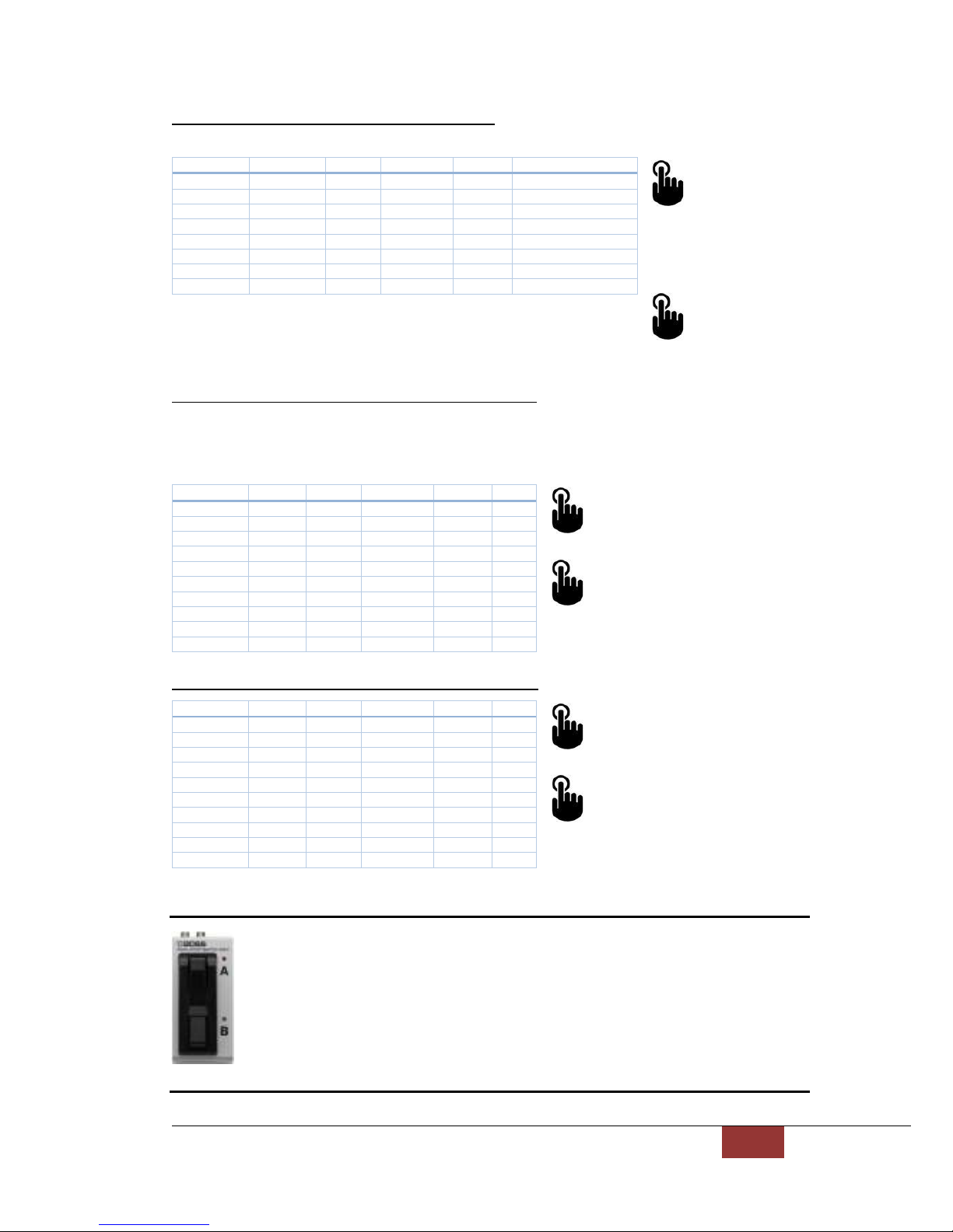
STEP 6 - Set Mode of CTRL1 “TIP” Foot swit h
x 1
The Mode will
in rement. After the last
mode it will resume at the
first.
x 2
Advan e to
the next step of the Wizard.
STEP 7 - Set CTRL1 “TIP” Foot swit h 1
st
Digit (Tens)
This number (Tens) ombined with the next step (Ones) is used by the Mode you have sele ted. If the
mode is CC# (lat hed or momentary) it’s the CC# to use. If it is PC# fixed then it’s the PC# to use. If it’s PC#
de rement/in rement, it’s the starting PC# when the unit is started up. For START, CONTINUE and STOP
this value has no meaning.
x 1
In rement the “Tens” digit.
x 2
Advan e to the next step of the
Wizard.
STEP 8 - Set CTRL1 “TIP” Foot swit h 2
nd
Digit (Ones
x 1
In rement the “Ones” digit.
x 2
Advan e to the next step of the
Wizard.
Notes:
BOSS FS-7: If the stereo plug is onne ted to ja k B, then FS-B is “TIP” and FS-A
is “RING”. If the stereo plug is onne ted to ja k A, the FS-A is “TIP” and ‘B’ is
not available. BOSS FS-6: If the stereo plug is onne ted to ja k A&B, then FS-B
is “TIP” and FS-A is “RING”. If CC# mode and CC#=0 then the foot swit h is off.
UPR MODE
UPR
LWR
MIDI OUT
MIDI IN
Di it
RED FLASH
RED FLASH
-
-
-
Send CC# Lat hed
RED FLASH
RED FLASH
-
-
GREEN
Send CC# Momentary
RED FLASH
RED FLASH
-
GREEN
-
Send fixed PC#
RED FLASH
RED FLASH
-
GREEN
GREEN
De rement PC#
RED FLASH
RED FLASH
GREEN
-
-
In rement PC#
RED FLASH
RED FLASH
GREEN
-
GREEN
Send START
RED FLASH
RED FLASH
GREEN
GREEN
-
Send CONTINUE
RED FLASH
RED FLASH
GREEN
GREEN
GREEN
Send STOP
UPR MODE
UPR
LWR
MIDI OUT
MIDI IN
Di it
RED
-
-
-
-
0
RED
-
-
-
GREEN
1
RED
-
-
GREEN
-
2
RED
-
-
GREEN
GREEN
3
RED
-
GREEN
-
-
4
RED
-
GREEN
-
GREEN
5
RED
-
GREEN
GREEN
-
6
RED
-
GREEN
GREEN
GREEN
7
RED
GREEN
-
-
-
8
RED
GREEN
-
-
GREEN
9
UPR MODE
UPR
LWR
MIDI OUT
MIDI IN
Di it
RED FLASH
-
-
-
-
0
RED FLASH
-
-
-
GREEN
1
RED FLASH
-
-
GREEN
-
2
RED FLASH
-
-
GREEN
GREEN
3
RED FLASH
-
GREEN
-
-
4
RED FLASH
-
GREEN
-
GREEN
5
RED FLASH
-
GREEN
GREEN
-
6
RED FLASH
-
GREEN
GREEN
GREEN
7
RED FLASH
GREEN
-
-
-
8
RED FLASH
GREEN
-
-
GREEN
9

MIDX-20 User’s Manual 15 15
STEP 9 - Set Mode of CTRL1 “RING” Foot swit h
x 1
The Mode
will in rement. After
the last mode it will
resume at the first.
x 2
Advan e
to the next step of the
Wizard.
STEP 10 - Set CTRL1 “RING” Foot swit h 1
st
Digit (Tens)
This number (Tens) ombined with the next step (Ones) is used by the Mode you have sele ted. If the
mode is CC# (lat hed or momentary) it’s the CC# to use. If it is PC# fixed then it’s the PC# to use. If it’s PC#
de rement/in rement, it’s the starting PC# when the unit is started up. For START, CONTINUE and STOP
this value has no meaning.
x 1
In rement the “Tens” digit.
x 2
Advan e to the next step of the
Wizard.
STEP 11 - Set CTRL1 “RING” Foot swit h 2
nd
Digit (Ones)
x 1
In rement the “Ones” digit.
x 2
Advan e to the next step of
the Wizard.
NOTE: AT THIS POINT THE WIZARD WILL CONTINUE WITH STEPS 12-19 TO CONFIGURE
CTRL2 JACK PROPERTIES. THESE STEPS ARE IDENTICAL TO STEPS 4-11.
UPR MODE
UPR
LWR
MIDI OUT
MIDI IN
Di it
GREEN FLASH
GREEN FLASH
-
-
-
Send CC# Lat hed
GREEN FLASH
GREEN FLASH
-
-
GREEN
Send CC#
Momentary
GREEN FLASH
GREEN FLASH
-
GREEN
-
Send fixed PC#
GREEN FLASH
GREEN FLASH
-
GREEN
GREEN
De rement PC#
GREEN FLASH
GREEN FLASH
GREEN
-
-
In rement PC#
GREEN FLASH
GREEN FLASH
GREEN
-
GREEN
Send START
GREEN FLASH
GREEN FLASH
GREEN
GREEN
-
Send
CONTINUE
GREEN FLASH
GREEN FLASH
GREEN
GREEN
GREEN
Send STOP
UPR MODE
UPR
LWR
MIDI OUT
MIDI IN
Di it
GREEN
-
-
-
-
0
GREEN
-
-
-
GREEN
1
GREEN
-
-
GREEN
-
2
GREEN
-
-
GREEN
GREEN
3
GREEN
-
GREEN
-
-
4
GREEN
-
GREEN
-
GREEN
5
GREEN
-
GREEN
GREEN
-
6
GREEN
-
GREEN
GREEN
GREEN
7
GREEN
GREEN
-
-
-
8
GREEN
GREEN
-
-
GREEN
9
UPR MODE
UPR
LWR
MIDI OUT
MIDI IN
Di it
GREEN
FLASH
-
-
-
-
0
GREEN FLASH
-
-
-
GREEN
1
GREEN FLASH
-
-
GREEN
-
2
GREEN FLASH
-
-
GREEN
GREEN
3
GREEN FLASH
-
GREEN
-
-
4
GREEN FLASH
-
GREEN
-
GREEN
5
GREEN FLASH
-
GREEN
GREEN
-
6
GREEN FLASH
-
GREEN
GREEN
GREEN
7
GREEN FLASH
GREEN
-
-
-
8
GREEN FLASH
GREEN
-
-
GREEN
9

MIDX-20 User’s Manual 16 16
MIDX-20CONNECTIONEXAMPLES
USB ‘UPR’ IS SET AS CTRL IN (or IN/OUT)
In this mode a USB foot ontroller plus external foot ontrollers and expression pedals
may ontrol for instan e a GP-10 and GR-55.
Guitar-to-MIDI from the GP-10 an be played ba k to a 5-Pin MIDI Synth.
USB ‘UPR’ IS SET AS DEV OUT (or IN/OUT)
In this mode the 5-PIN MIDI foot ontroller and the FS-7, EV-5s ontrol three devi es, GT-
001, GP-10 and GR-55.
Guitar-to-MIDI from the GP-10 an be played ba k to any 5-Pin MIDI Synth.

MIDX-20 User’s Manual 17 17
Another two-devi e example, ontrolling both a Mustang™ and a GP-10:

MIDX-20 User’s Manual 18 18
REAL-TIMEMESSAGES
MIDI Clock - When power is first applied, no input is defined as a master and all lo k
messages from both inputs will be passed until one input is defined as a master. The
input to re eive the most re ent START ommand will be ome the lo k master. That
input ontinues to be the lo k master until another input satisfies the above ondition.
Active Sensin - The first input to re eive an a tive sensing message will be ome the
a tive sensing master. A tive sensing messages from that input will be passed to the
output and any a tive sensing messages re eived at other inputs will be ignored. The
input will remain the a tive sensing master until no additional a tive sensing messages
are re eived at that input for a period of a few se onds. Then the other input has the
opportunity to be ome the a tive sensing master.
MIDX-20MODES/MIDIDATAFLOW
As there are three bidire tional MIDI onne tions (2xUSB + Standard MIDI) and two
ontroller ja ks, the flow of data between the onne tors an be onfigured in many
different ways. To over most ases, four modes have been ele ted for the MIDX-20,
sele ted using the SET button. A LONG HOLD of the button will y le through the four
modes and the urrent mode will show on the UPR MODE LED.
LED is OFF – Mode for two USB devi es, UPR is only sending data.
LED is RED – Mode for two USB devi es, UPR is bidire tional.
LED is GREEN – Mode for a USB Controller on UPR, UPR is only re eiving data.
LED is YELLOW – Mode for a USB Controller on UPR, UPR is bidire tional.
Ea h of the four modes may also have MIDI THRU/MERGE ON or OFF rendering the total
number of possible onfigurations to eight. The following flow harts des ribes in detail
how the unit operates in these eight modes.
This symbol is used to indi ate a merge of two or more MIDI data streams.
If there’s a ollision between USB messages, the message started first gets priority to
omplete before the other stream is allowed to pass through.
Note:
The MIDI MERGE mode allows for forwarding MIDI data and daisy- haining several
devi es (or MIDX-20 units) via the 5-Pin MIDI onne tions.
+

MIDX-20 User’s Manual 19 19
UPR IS ‘DEV OUT’ and MIDI THRU/MERGE is ‘OFF’
UPR IS ‘DEV OUT’ and MIDI THRU/MERGE is ‘ON’

MIDX-20 User’s Manual 20 20
UPR IS ‘DEV IN/OUT’ and MIDI THRU/MERGE is ‘OFF’
UPR IS ‘DEV IN/OUT’ and MIDI THRU/MERGE is ‘ON’
Table of contents
Other Primova Amplifier manuals


