Audio Creative DDDAC1794 User manual

AudioΩCreative DDDAC1794
1
Version 1.1
Finally !! The new, highly improved ‘2016’ DDDAC1794 module! De voltage regulation at
the analog side of the system has now an embedded Tentlabs Shunt regulator. The Bias
through the much discussed ‘pin 20’ got a constant current source (CCS) which replaces
the fixed 6K1 resistor. All resulting in the next stage of superb sound reproduction

AudioΩCreative DDDAC1794
2
Few ps before the work starts...
Of course you will need a good soldering staon. Use one with variable temperature or at
least one with a thermostat to keep the temperature constant. Keep the p clean by wip-
ing every me across a wet sponge. Only keep a lot of n on it when you let it cool of. This
will increase the life me of the p.
Further necessary tools are a ne cable cuer, beak tang and tweezers (or platbek tang).
For easy mounng of the module on the mainboard it is good to use a screwdriver and a
socket spanner.
The construcon me of one module is approximately 30 minutes.

AudioΩCreative DDDAC1794
3
The construcon
We will start with soldering the resistors. Important point: do not place the 6k1 resistor.
ONLY when you want to experiment with ‘pin 20’ by not using the CCS, in which case you
should NOT install the trimmer and 100Ohm resistors… The SMD parts are already mount-
ed so you only have to install the resistors and trimmer.
De original 6k1 is an opon in STEAD of the CCS.
TIP: only do this to experiment. The CCS is a very nice upgrade you most likely want.
Combining old and new DAC Module boards is no problem at all. They are fully
backwards compable. To do this is up to you of course. But technically it is no problem.

AudioΩCreative DDDAC1794
4
Let’s start...
First we solder the two 4,7 Ohm resistors on the PCB ...
The bending tool, see picture above, is a very handy tool to make a perfect t. The PCB has
exact this distances.
Let the solder ow nicely round the wires (must be shiny) and cut the wires with the cable
cuer. Cut them directly above the solder pad.

AudioΩCreative DDDAC1794
5
Than solder the two 100Ohm resistors.
Heat it well and take the me needed to have the solder ow nicely.
Cut the wires and you might want to re-heat /re-solder shortly the connecons, so it even
looks beer. This is not a must, just some perfecon thing …

AudioΩCreative DDDAC1794
6
Capacitors
Next we will solder the 18 pcs of the 100nF capacitors. Best is to put them on the pcb and
slightly bend the two wires to the outside so they will not fall o the board anymore.
Place the PCB on its back on a at working space. Make sure all capacitors are placed
correctly. Press slightly to make sure this is the case. Now solder all 36 connecons. Cut
them short with the cable cuer.

AudioΩCreative DDDAC1794
7
It will look like this at this stage...

AudioΩCreative DDDAC1794
8
The electrolyc capacitors (elcos)
There are 12 pcs of the 10uF and 2 pcs of the 47uF Elcos to be mounted.
When placing the elcos make sure (check AND double check) that the polarizaon (plus
and minus wires) are correct!
A wrong connecon is very dicult to correct aer they are soldered.

AudioΩCreative DDDAC1794
9
Again, take your me to let the solder ow. Specially the “minus” poles are at the ground
plane which will aract quite some heat in the rst few seconds when the solder p is
placed. So do not “bake” the solder on the pads. Let it ow.

AudioΩCreative DDDAC1794
10
Specially here it make sense to cut very short (2mm above PCB area) and (oponally)
resolder the connecons. If more modules are mounted above each other we must avoid
that long wires scking out are shortcung against the capacitores on the below deck.
Now the same with the two 47uF capacitors

AudioΩCreative DDDAC1794
11
In between view of the PCB
The voltage regulators
Before mounng we bend the pins with the platbek tang. Directly aer the thicker part of
the pins.

AudioΩCreative DDDAC1794
12
Press the connecon pins through the PCB. Solder the middle pin with a small drop while
making sure the voltage regulator is nicely placed on the PCB. (See image).

AudioΩCreative DDDAC1794
13
Here it is best to cut the wires rst a few mm above the PCB and than solder the two out-
side pins. Do not forget to re-solder the middle pin...
Trimmers
As you can see, the only thing missing are the two blue mul turn trimmers for the CCS...

AudioΩCreative DDDAC1794
14
Place the trimmers in the correct holes and bend the wires a lile bit to the outside.
Solder the wires and cut them short.
The adjusng of the CSS can only be done aer the dac module is installed on the main
board. The measurement control point is the solder pad directly next to the trimmer.
Here we need a DC voltage of + 40mV (hold the red ‘plus’ of your DMM at this point)
Hold the minus (black) of the mul meter (DMM) to the analog output pin ’com’ from the
main board. Note that if you adjust the ‘le’ channel you also use the ‘com’ of the le
channel and vise versa for the right channel of course
The adjustment is not crical. Nothing can go wrong. Just turn ll you have approximately
40mV. Wait 20 minutes ll the DAC is warm and check and re-adjust a bit if needed.
IMPORTANT!! It is not allowed to connect a sole DAC module to a 12 volt power supply
just to “quickly test” it. This can ONLY be done aer it is mounted and connected on the
main board where the Rload resistors (Ra / Rb combinaon) are also installed

AudioΩCreative DDDAC1794
15
Unless we tried to be as clear and complete as possible in this con-
strucon manual, we cannot exclude that sll something is unclear.
In that case just email Audio Creave or DDDAC for further help!
Also feedback to improve on text or image is more than welcome
Dick van de Merwe Doede Douma
Audio Creave DDDAC Audio Design
Popular Control Unit manuals by other brands

Quectel
Quectel SC606T Series Hardware design
AVK
AVK 715 Series Installation, operation and maintenance manual

Vetus
Vetus VRF56 installation instructions

KIESELMANN
KIESELMANN 582x Operating instruction
Extron electronics
Extron electronics DVCM 50 user manual
Baker Hughes
Baker Hughes Masoneilan 71000 Series instruction manual
Omnitron
Omnitron iConverter TM3 quick start guide

Mitsubishi Electric
Mitsubishi Electric QJ71DN91 user manual
Adesys
Adesys Octalarm EM-8001 quick start
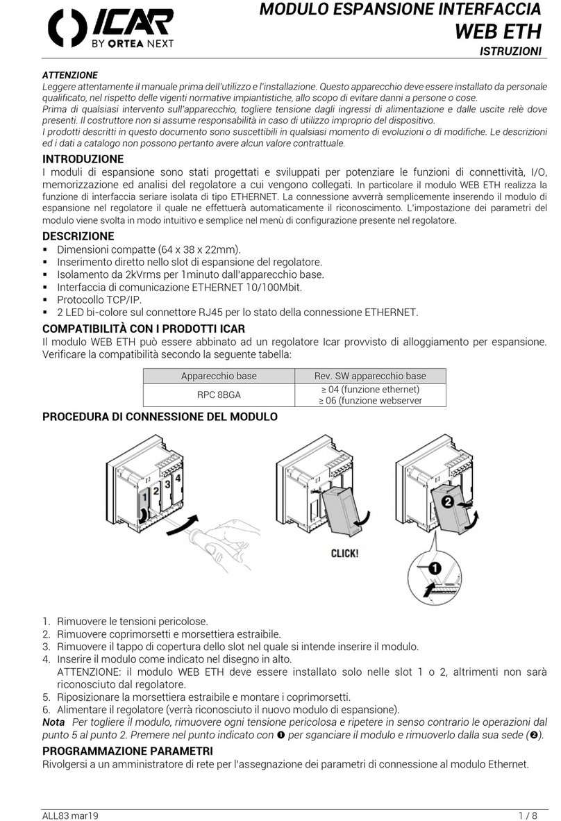
ORTEA NEXT
ORTEA NEXT ICAR WEB ETH instructions
Bull
Bull 1GB Intel Ethernet Switch Module Installation and user guide
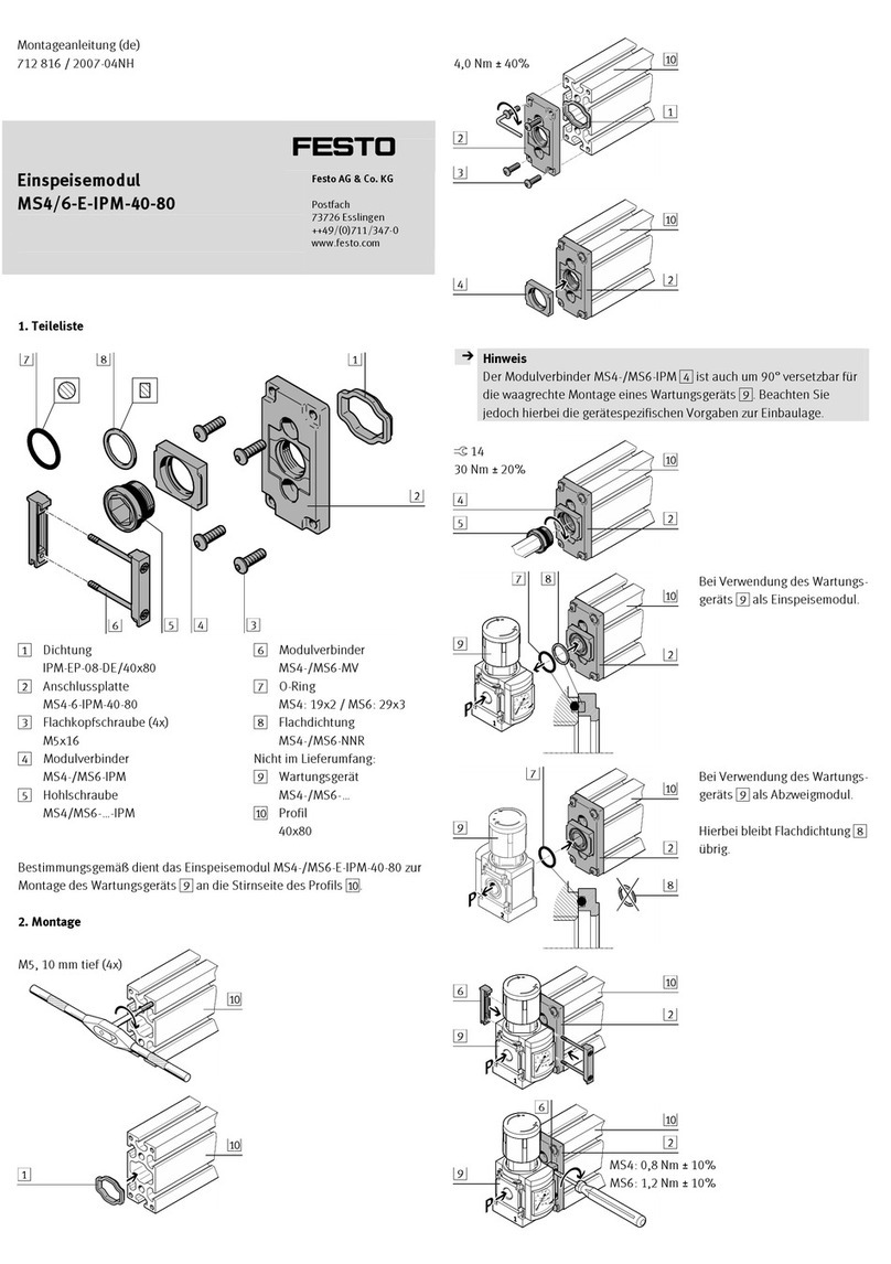
Festo
Festo MS4/6-E-IPM-40-80 Assembly instructions
