Audio Precision AUX Series User manual


AUX-0025, AUX-0040 and AUX-0100
Switching Amplifier
Measurement Filters
User’s Guides and Specifications
February, 2017
AUX-0025

Copyright © 2011–2017 Audio Precision, Inc.
All rights reserved.
Printed in the United States of America.
No part of this manual may be reproduced or transmitted
in any form or by any means, electronic or mechanical, in-
cluding photocopying, recording, or by any information
storage and retrieval system, without permission in writing
from the publisher.
Audio Precision, AP, and APx are trademarks of Audio
Precision, Inc. Windows™ is a trademark of Microsoft Cor-
poration. Dolby and the double-D symbol are trademarks
of Dolby Laboratories, Inc. DTS is a trademark of DTS, Inc.
pn 8211.0349 rev 000 XVII0206162505
Audio Precision
5750 SW Arctic Drive
Beaverton, Oregon 97005
503-627-0832
800-231-7350
ap.com

Documentation and Support
This booklet contains safety information, user’s guides and full specifications for the
Audio Precision AUX-0025, AUX-0040 and AUX-0100 Switching Amplifier Measurement
Filters. The AUX series of filters are accessories to anyAudio Precision audio analyzer.
ap.com
Visit the Audio Precision web site at ap.com for APx support information andAPx
resources. You can also contact our Technical Support staff at techsupport@ap.com, or by
telephoning 503-627-0832 ext. 4, or 800-231-7350 ext. 4 (toll free in the U.S.A.).


AUX-0025/0040/0100 Measurement Filters: Contents i
Table of Contents
Safety . . . . . . . . . . . . . . . . . . . . . . . . . . . . . . . . . . . . . . . . . . . . . . . . . . . . . . . . . . . . . . . . . . iii
Introduction . . . . . . . . . . . . . . . . . . . . . . . . . . . . . . . . . . . . . . . . . . . . . . . . . . . . . . . . . . . . . . . 1
User’s Guides . . . . . . . . . . . . . . . . . . . . . . . . . . . . . . . . . . . . . . . . . . . . . . . . . . . . . . . . . . . . . .11
Abbreviations, Terms and Symbols . . . . . . . . . . . . . . . . . . . . . . . . . . . . . . . . . . . . . . . . . . . . . . . . . . . 15
Specifications . . . . . . . . . . . . . . . . . . . . . . . . . . . . . . . . . . . . . . . . . . . . . . . . . . . . . . . . . . . . . . 17


AUX-0025/0040/0100 Measurement Filters: Safety iii
Safety
Safety Information
Do NOT service or repair this equipment unless properly
qualified. Servicing should be performed only by a quali-
fied technician or an authorized Audio Precision distributor.
Do NOT substitute parts or make any modifications with-
out the written approval of Audio Precision. Doing so may
create safety hazards. Using this product in a manner not
specified by Audio Precision can result in a safety hazard.
This product is for indoor use—Installation Category II,
Measurement Category I, pollution degree 2.
To clean the enclosure of this product, use a soft cloth or
brush to remove accumulated dust. A mild detergent may be
used to remove remaining dirt or stains. Do not use strong
or abrasive cleaners. Wipe all surfaces with a damp cloth.
Safety Symbols
The following symbols may be marked on the panels or
covers of equipment or modules, and are used in this man-
ual:
WARNING!—This symbol alerts you to a potentially haz-
ardous condition, such as the presence of dangerous volt-
age that could pose a risk of electrical shock. Refer to the
accompanying Warning Label or Tag, and exercise extreme
caution.

Chapter 1: Safety
iv AUX-0025/0040/0100 Measurement Filters: Safety
ATTENTION!—This symbol alerts you to important oper-
ating considerations or a potential operating condition that
could damage equipment. If you see this marked on equip-
ment, refer to the Operator’s Manual or User’s Manual for
precautionary instructions.
FUNCTIONAL EARTH TERMINAL—A terminal marked
with this symbol is electrically connected to a reference
point of a measuring circuit or output and is intended to be
earthed (grounded) for any functional purpose other than
safety.
PROTECTIVE EARTH TERMINAL—A terminal marked
with this symbol is bonded to conductive parts of the instru-
ment and is intended to be connected to an external protec-
tive earthing (grounding) system.
Disclaimer
Audio Precision cautions against using their products in a
manner not specified by the manufacturer. To do otherwise
may void any warranties, damage equipment, or pose a
safety risk to personnel.

AUX-0025 / 0040 / 0100 Measurement Filters: Introduction 1
Introduction
Audio analyzers are generally designed to have broad mea-
surement bandwidths, broader than a typical audio circuit or
system and much wider than the audio passband. Such
designs enable accurate analysis of fast, high-performance
audio circuits and also allow measurement of any low-level,
high-frequency spurious signals that may accompany the
audio signal.
This design philosophy is based on the assumption that the
audio signal and its overtones are the dominant signal com-
ponents applied to the analyzer; this is the case for the out-
put of conventional audio power amplifiers of Class Aor
Class AB design. In such a case the analyzer can range its
circuits to the amplitude of the audio signal for optimum
measurement conditions.
Recent practice, however, has often turned to other ampli-
fier designs for improvements in efficiency and weight as
compared to Class A and Class AB amplifiers. Although
these amplifier designs vary, as do the names applied to
them, they have in common an output signal that is a high-
frequency switching carrier modulated by the audio signal.
Many of these “switching amplifiers” or “digital amplifi-
ers” present a difficulty to conventional measurement and
analysis techniques due to the out-of-band switching carrier
components that are in the output signal. When the ampli-
tude of the switching carrier components remains high in
comparison to the audio signal, the ranging functions of an
audio analyzer may respond to the carrier rather than to the
audio signal; also, the slew rate of the analyzer input ampli-
fiers may be exceeded. Either will reduce the accuracy of
the measurements.
The best solution in using a broad range, broad bandwidth
analyzer to accurately measure the output of such an ampli-
fier is to insert a carefully designed low-pass filter between
the output of the device under test (DUT) and the analyzer

Chapter : Introduction
2 AUX-0025 / 0040 / 0100 Measurement Filters: Introduction
input to reduce amplitude of the switching carrier before the
signal is ranged. The Audio Precision AUX-0025, AUX-
0040 and AUX-0100 family of switching amplifier mea-
surement filters fulfills this requirement.
A switching amplifier by any name...
In this document we will refer to audio amplifiers with
modulated switching carrier outputs as switching amplifi-
ers; in other literature the term switchmode amplifier may
be used. These devices include Class D, Class I and Class S
amplifiers and also Class T amplifiers and “digital amplifi-
ers.”
Generally, switching amplifiers impose the audio signal on
the carrier by pulse width modulation (PWM). (Class T is a
variation on this, adding a dynamic modulation of the car-
rier frequency and other signal processing.)
A diagram of a sine wave and a pulse width modulated
(PWM) switching carrier modulated by the same wave.
Switching amplifiers designed for a limited bandwidth
(such as subwoofer amplifiers) may use a carrier frequency
as low as 80 kHz. Full-range amplifiers have higher carri-
ers, up to 1.5 MHz or more.
Some switching amplifiers provide no filtering at their out-
put and depend upon the inductance and mass of the loud-
speaker to integrate the signal, reproducing the audio but
not the inaudible carrier. Other amplifiers include an output
low-pass filter, which reduces EMI and aids the loud-
speaker in integrating the signal, but which is generally not
sufficient for accurate measurement by an external analyzer.
Features of the filters
Each channel of an AUX-0025/0040/0100 is a passive low-
pass filter specifically designed to minimize switching
amplifier carrier components while passing a broad audio
spectrum. The filter provides the signal preconditioning
necessary to accurately measure switching amplifier out-
puts using a wide-range audio analyzer.
Passive design
For this application, a passive filter was determined to be
the best approach. An active filter would require input
attenuation and variable gain to accommodate the wide
range of signal amplitudes that might be applied, adding
noise and distortion to the signal.
Inductors
Custom inductors were specified with an emphasis on
power handling and minimizing low-frequency distortion
while satisfying the filter response requirements.

Chapter : Introduction
AUX-0025 / 0040 / 0100 Measurement Filters: Introduction 3
Typical waveforms
An oscilloscope capture of a switching amplifier output
signal. The high-frequency, high-level switching carrier is
shown riding the lower-frequency audio.
A second oscilloscope capture of the same switching
amplifier output shown in Figure 4,
after the application of the AUX-0025 filter.
The switching carrier has been greatly reduced.
The two oscilloscope traces above show time-domain
views of the unfiltered and filtered output for a particu-
lar amplifier. Different amplifiers and load configura-
tions can produce oscilloscope waveforms that are quite
different than these.
Use of additional filters
The AUX filters reduce the switching carrier and other out-
of-band components to a sufficient degree for accurate mea-
surement, but they are not designed to remove all out-of-
band noise.
In many cases you may want to apply additional low-pass
filtering within the analyzer.
Mounting
The AUX filters are fitted with resilient feet for tabletop
use. They can also be rack-mounted using the optional rack
mount adapters available fromAudio Precision. Being a
passive unit, an AUX filter does not dissipate appreciable
power and requires no extraordinary ventilation consider-
ations.
The AUX filter should not be mounted close to a source of
strong magnetic fields such as a power transformer. Stray
magnetic fields could cause degradation in system residual
hum and noise performance.
Audio Precision analyzers are designed to mini-
mize and contain stray magnetic and electro-
static fields that may be produced within the
instrument. An AUX-0025/0040/0100 filter may
be placed directly on top of an Audio Precision
analyzer with no degradation in system perfor-
mance.

Chapter : Introduction
4 AUX-0025 / 0040 / 0100 Measurement Filters: Introduction
Use with Audio Precision switchers
The characteristics of the Audio Precision SWR-2122 or
SWR-2755 series switchers are completely compatible with
the AUX-0025/0040/0100. The appropriate balanced or
unbalanced switcher can be used to automatically switch the
filter / instrument inputs among several DUTs.
For more information about your Switching Amplifier Mea-
surement Filter and switching amplifiers in general, visit the
Audio Precision Web site at ap.com.

Chapter : Introduction
AUX-0025 / 0040 / 0100 Measurement Filters: Introduction 5
Typical Response Curves
AUX-0025 and AUX-0100
AUX-0025 and AUX-0100 filter passband
2010 50 100 200 500 1k 2k 5k 10k 20k 50k30k
Hz
-0.10
-0.08
-0.06
-0.04
-0.02
0
+0.02
+0.04
+0.06
+0.08
+0.10
d
B
V
AUX-0025 / AUX-0100 frequency response
specied at ±0.05 dB 20 Hz to 20 kHz.

Chapter : Introduction
6 AUX-0025 / 0040 / 0100 Measurement Filters: Introduction
AUX-0025 and AUX-0100 filter cutoff
2010 500k50 100 200 500 1k 2k 5k 10k 20k 50k 100k 200k
Hz
-60
-65
+5
-55
-50
-45
-40
-35
-30
-25
-20
-15
-10
-5
+0
d
B
V
AUX-0025 / AUX-0100 high frequency rejection
typically >50 dB, 250 kHz to 20 MHz

Chapter : Introduction
AUX-0025 / 0040 / 0100 Measurement Filters: Introduction 7
AUX-0040
AUX-0040 filter passband
2010 50 100 200 500 1k 2k 5k 10k 20k 50k 100k
Hz
-0.10
-0.08
-0.06
-0.04
-0.02
0
+0.02
+0.04
+0.06
+0.08
+0.10
d
B
V
AUX-0040 frequency response specied at ±0.08 dB 20 Hz to 40 kHz.

Chapter : Introduction
8 AUX-0025 / 0040 / 0100 Measurement Filters: Introduction
AUX-0040 filter cutoff
2010 500k50 100 200 500 1k 1M2k 5k 10k 20k 50k 100k 200k
Hz
-60
-65
+5
-55
-50
-45
-40
-35
-30
-25
-20
-15
-10
-5
+0
d
B
V
AUX-0040 high frequency rejection typically >52 dB, 400 kHz to 20 MHz

AUX-0025 / 0040 / 0100 Measurement Filters: User’s Guides 9
User’s Guides
AUX-0025

Chapter : User’s Guides
10 AUX-0025 / 0040 / 0100 Measurement Filters: User’s Guides
AUX-0040
AUX-0100
The three filters discussed here are quite similar. The two-
channel AUX-0025 and AUX-0040 share the same mechan-
ical design and connectors, but differ in their bandpass: the
AUX-0025 has a flat response from 20 Hz to 20 kHz with a
sharp cutoff above that point, while the AUX-0040 extends
its response to 40 kHz before falling off.
The eight-channelAUX-0100 has the same 20 Hz to
20 kHz response as the AUX-0025, but is AC coupled.
For proper performance, the analyzer input impedance that
the AUX filters look into must be high. The DUT output
impedance must be low (< 2 ) as well, but this is consis-
tent with switching amplifier designs.
This manual suits for next models
3
Table of contents
Popular Water Filtration System manuals by other brands

Sentinel
Sentinel KalGuard installation manual

Aquatec
Aquatec DC 500 user manual

Fleck
Fleck 7000 Installation & start?up guide
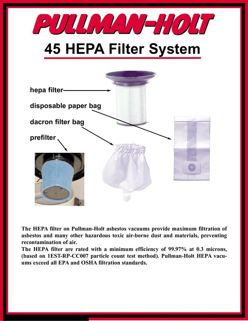
Pullman Holt
Pullman Holt 45 HEPA supplementary guide
Judo
Judo LongLife JUKO-LF-A 3/4 Addition to the installation and operating instructions
Whirlpool
Whirlpool WHCF-DWH Installation, use & care guide
