Audiolab MAGNA 118A User manual

P. 1
- AUDIOLAB Magna 118A
MAGNA 118A
Self-powered subwoofer – 1 x 18”
USER MANUAL

P. 2
AUDIOLAB Magna 118A -
MAGNA 118A
Self-powered subwoofer – 1 x 18”
Magna 118A is an 18" self-powered subwoofer
with a 3" voice coil that delivers 1000W contin-
uous. Thanks to its D-type amplication, the
subwoofer reaches a great power with a very
good sound quality and a very low weight design.
Magna 118A has a frequency response ranging
from 40Hz to 120Hz and has a control panel that
allows inverting the phase and applying a 100Hz
high-pass lter for the top units. Ideal for medi-
um-scale mobile applications thanks to its rugged
construction, its amplication also features a
highly ecient protection circuit.
Specications
Components
• LF: 1 x 18" Woofer with 3" voice coil
Features
• Self-powered 18" Subwoofer
• Crossover frequency: Low pass band type 12
dB/oct
• Frequency response (-6dB): 40Hz-120Hz
• Max SPL: 129 dB @ 1M
• Cooling: Temperature-controlled fan
• Enclosure design: Plywood cabinet, resistant
black paint, metal grille with foam & rubber feet
• Mounting: One metal standard pole-mount
Amplier & Control
• Power output: 1000W RMS
• Amplier type: Class D
• Protections: Thermal / Convection-Fan / Over-
load / Digital Compressor / Limit
• Controls: Volume Control / Phase switch /
HPF-100Hz L-R satellite or bypass / Ground
Lift
Connectors
• Inputs:
• 1 XLR-3/Plug combo
• 1 XLR-3
• Output: 2 XLR-3
• Link: 2 XLR-3
Physical
• Dimensions: 535x661x515 mm. / 21x26x20.3 in.
• Weight: 31.8 Kg. / 70 Lbs.
1. OVERVIEW
English version
P. 3
- AUDIOLAB Magna 118A
English version
2. SAFETY RELATED SYMBOLS
To reduce the risk of electric shock please do
not remove the cover or the back panel of this
equipment.
There are no parts needed by user inside the
equipment. For service, please contact quali-
ed service centers.
This symbol, wherever used, alerts you
to the presence of un-insulated and
dangerous voltages within the product
enclosure. These are voltages that may be suf-
ecient to constitute the risk of electric shock or
death.
This symbol, wherever used, alerts you
to important operating and mainte-
nance instructions.
Protective Ground Terminal.
AC mains (Alternating Current)
Hazardous Live Terminal
ON: Denotes the product is turned on.
OFF: Denotes the product is turned o.
Caution
Describes precautions that should be observed to
prevent damage to the product.
1. Read this Manual carefully before operation.
2. Keep this Manual.
3. Be aware of all wamings reported with this
symbol.
4. Keep this Equipment away from water and
moisture.
5. Clean it only whith dry doth. Do not use sol-
vent or other chemicals.
6. Do not damp or cover any cooling opening.
Install the equipment only in accordance
with the Manufacturer's instructions.
7. Power Cords are designed for your safety.
Do not remove Ground connections! If the
plug does not t your AC outlet, seek advice
from a qualied electrician. Protect the pow-
er cord and plug from any physical stress
to avoid risk of electric shock. Do not place
heavy objects on the power. This could cause
electric shock or re.
8. Unplug this equipment when unused for
long periods of time or during a storm.
9. Refer all service to qualied service person-
nel only. Do not perform any servicing other
than those instructions contained whithin
the User's Manual.
10. To prevent re and damage to the product,
use only the recommended fuse type as
indicated in this manual. Do not short-circuit
the fuse holder.
Warning
To reduce the risk of electric shock and re,
do not expose this equipment to moisture or
rain.
Dispose of this product should not be placed
in municipal waste and should be separate
collection.
11. Move this Equipment only with a cart,
RISK OF ELECTRIC SHOCK
DO NOT OPEN.
CAUTION!

P. 4
AUDIOLAB Magna 118A - English version
stand, tripod, or bracket,
specied by the manufac-
turer, or sold with the Equip-
ment. When a cart is used, use
caution when mobing the cart/
equipment combination to
avoid possible injury from tip-over.
12. Permanent hearing loss may be caused by
exposure to extremely high noise levels. The
US Government's Occupational Safety and
Health Administration (OSHA) has specied
the permissible exposure to noise level.
These are shown in the following chart:
According to OSHA, an exposure to high SPL in
excess of these limits may result in the loss of heat.
To avoid the potential damage of heat, it is recom-
mended that Personnel exposed to equipment
capable of generating high SPL use hearing protec-
tion while such equipment is under operation.
The apparatus shall be connected to a mains sock-
et outlet with a protective earthing connection.
The mains plug or an appliance coupler is used as
the disconnect device, the disconnect device shall
remain readily operable.
Hours x day SPL Example
890 Small gig
692 Train
495 Subway train
397 High level desktop monitors
2100 Classic music concert
1.5 102
1105
0.5 110
0.25 or less 115 Rock Concert
P. 5
- AUDIOLAB Magna 118A
English version
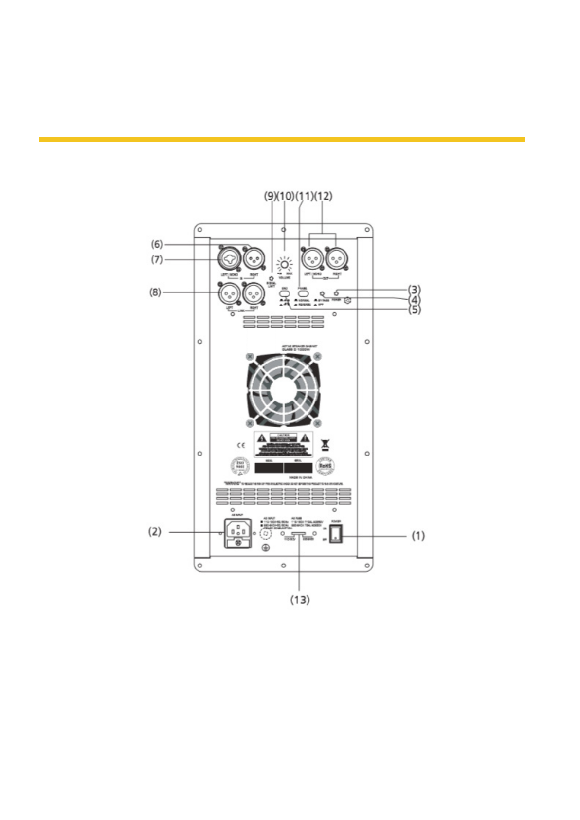
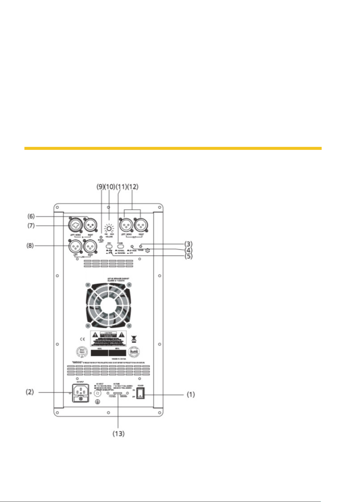
3. BACK PANEL DESCRIPTION
9. Signal/limit, red LED, indicate on status
10. Volume main power amplier control
11. Phase switch reverse the polarity of sub out
12. Out left/right on 2xXLR connector
13. Powerswitchselector
1. ON-OFF main power switch
2. Input AC power socket with main fuse
3. Power, green LED, indicate on status
4. Bypass switch select high pass lter or bypass
5. Ground lift switch
6. Line in right on XLR connector
7. Line in left/mono on combo connector
8. Link left/right on XLR connector

P. 6
AUDIOLAB Magna 118A - English version
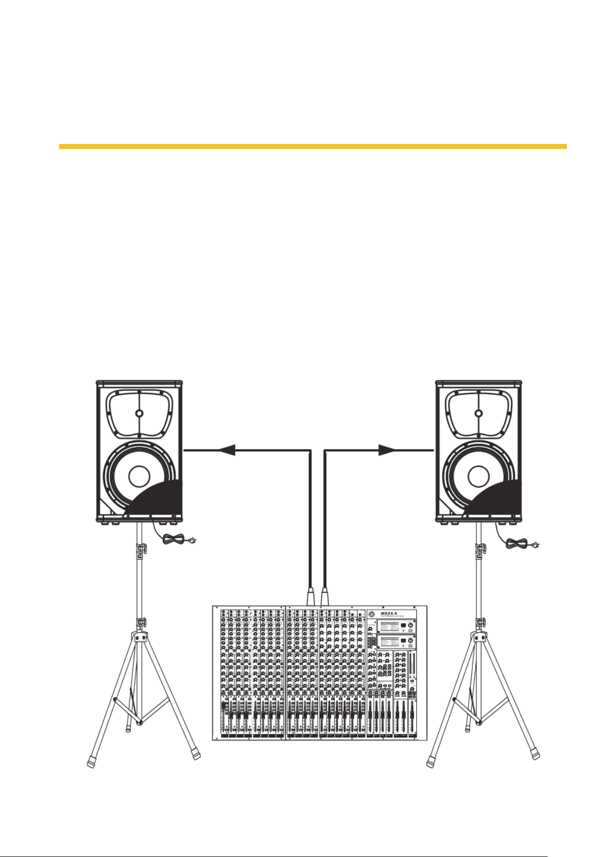
4. CONNECTION PLATE
Make your initial connections with all the equip-
ment powered o, and ensure that all the main
volume controls are turned completely down.
For active Full-range Speaker Cabinet
1. Connect one side of the signal cable at your
mixer into Output Left/Right (with Stereo-Jack
or XLR) and the other side of the cable into
the Line Input (COMBO) of your active speaker
cabinet (with Stereo-Jack or XLR).
2. Connect the power cords to main.
3. Turn on yout mixer rst, then the active
speaker cabinets.
4. Turn uo the volume controls of the active
speaker cabinets.
5. Use PFL function to get the proper input
level fot the mixer, and adjust the Main Mix
Level control to manipulate the output level.
6. After using, turn o your active speaker cabi-
nets rst, the the mixer.
signal cable
Mixer
Left
Main Mix
Output
Right
Main Mix
Output Tripod
mount
Tripod
mount
signal cable
P. 7
- AUDIOLAB Magna 118A
English version
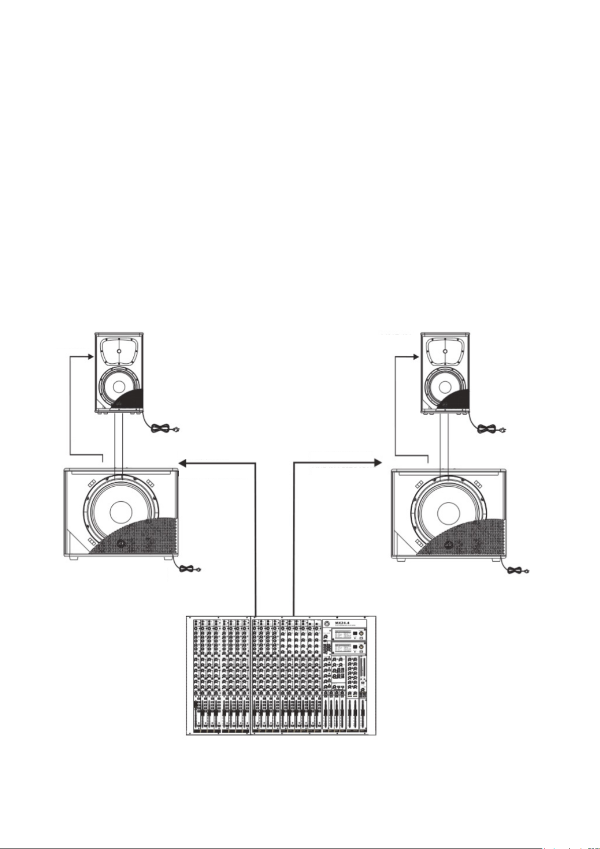
Two Active Subwoofers & Two Active Satellite
Speakers
1. Make your initial connections with all the
equipment powered o, and ensure that all
the main volume controls are turned com-
pletely.
2. Connect one side of the signal cable at your
audio mixer into OUTPUT LEFT/RIGHT, and the
other side of the cable intro the LINE INPUT of
your active subwoofers.
3. Connect one side of another signal cable at
your active subwoofers into LINK LEFT/RIGHT
or OUT LEFT/RIGHT, and the other side of the
cable into the LINE INPUT LEFT/RIGHT of your
active satellite speakers. *If you connect into
the OUT LEFT/RIGHT, and press the BYPASS
switch, the 80Hz HPF will be activated.
4. Connect the power cords to main.
5. Turn on your mixer rst, then the active
speaker cabinets.
6. Turn up the volume controls of the active
speaker cabinets.
7. Use PFL function to get the proper input
level for the mixer, and adjust the Main Mix
Level.
8. After using, turn o your active speaker cabi-
nets rst, the the mixer.
LINE IN
Pole
Mixer
Main out left Main out right
Line in Left/Mono Line in Left/Mono
Pole
LINE IN
P. 8
AUDIOLAB Magna 118A - English version
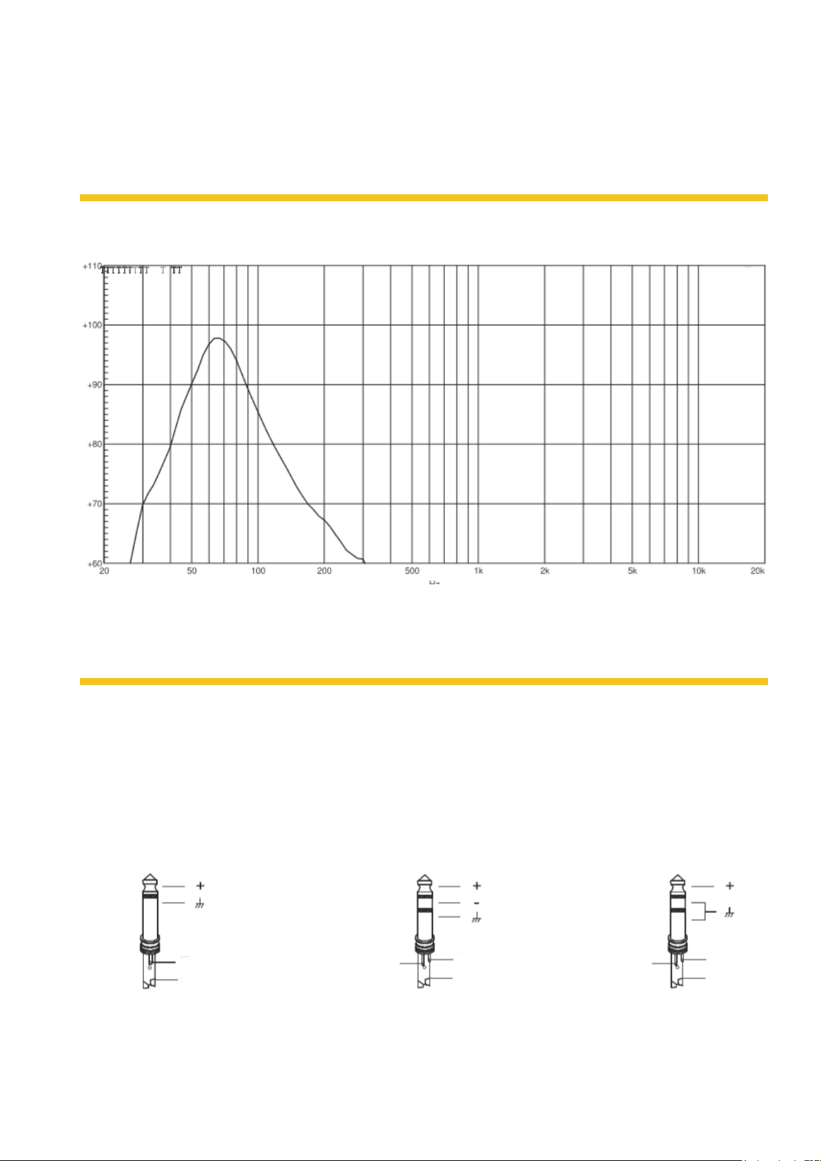
5. FREQUENCY RESPONSE DIAGRAM
dB SPL
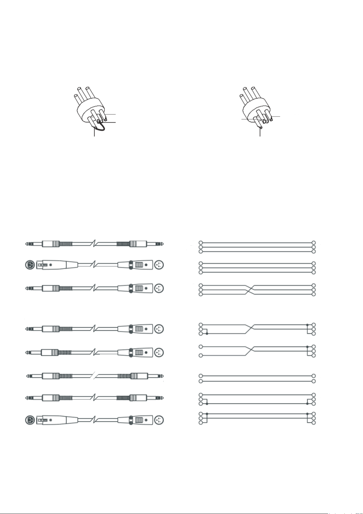
6. WIRE CONNECTIONS
Either the 1/4" TRS phone jack or XLR connector
can be wired in balanced and unbalanced modes,
which will be determined by the actual application
status, please wire your system as the following
wiring examples:
TS Type Unbalanced TRS Type Balanced TRS Type Unbalanced
Tip Tip Tip
Sleeve Sleeve Sleeve
Ring Ring
For 1/4" Phone jack
P. 9
- AUDIOLAB Magna 118A
English version
In-line Connection
For these applications the unit provides 1/4" TRS
and XLR connectors to easily interface with most
professional audio devices. Follow the conguration
examples below for your particular connection.
For XLR Connector
XLR Type Unbalanced XLR Type Balanced
Pin2 (+) Pin2 (+)
Pin3 (-) Pin3 (-)
Pin1 Pin1
(Linked to Pin1 manually)
Balanced
Unbalanced
Tip Ring Sleeve
Tip Ring Sleeve
Tip Ring Sleeve
Tip Ring Sleeve Tip Ring Sleeve
Tip Sleeve
Tip Sleeve
Tip Tip
1
1
1Tip
Ring Ring
2
2
2Ring
Sleeve Sleeve
3
3
3Sleeve
1
2
3
1
1
2
2
3
3
Sleeve Ring Tip
Sleeve Tip
Tip
Tip
Sleeve
Sleeve
Tip
Tip
Ring
Ring
Sleeve
Sleeve
1
2
3
Tip
Tip
Ring
Sleeve
Sleeve

P. 1 0
AUDIOLAB Magna 118A - English version
7. GUARANTEE
AMPRO guarantees the normal operation of the
product against any defect of manufacture and/
or vice of material, by the of (12) month, count-
ed as of the date of purchase on the part of the
user, comminting itself to repair or to change, to
its election, without pasition some, any piece or
component that will fail in normal conditions of
use within the mentioned period.
This guarantee is valid if the original buyer will
have to present/display this certicate properly
sealed and signed by the selling house, accom-
panied by the corresponding invoice of purchase
where ir consisted the model and serial number of
the acquired equipment.
The guarantee does not cover:
• Damages caused by the illegal use of product,
repair and/or nonauthotized modication
conduced by people by AMPRO.
• Damages causes by the connection of the
equipment to other equipment dierent from
the specied ones in the manual of use, or by
bad connection to these last ones.
• Damages caused by excesses or falls of
tension in the network or by connection to
networks with a tension dierent from the
required one by the unit.
• Damages caused by the presence of sand, acid
of batteries, water, or any strange element
inside the equipment.
• Deteriorations produced by the course of the
time, use and/or normal wear of the unit.
• Alteration of absence of the serial number of
factory of the equipment.
The repairs could only be carried out the author-
ized technical service by AMPRO, that will inform
about the term and other details into the repairs
to take place according to this guarantee.
AMPRO, will repair this unit in counted a termn
nongreater to 30 days as of the date of entrance
of the unit to the Technical Service. In those
cases in that due to the particularitity of the
spare part, outside necessary their import, the
repair time and the viability of the same one will
be subject to the eective norms fot the import
of part, in which case one will inquire to the user
about the term and possibility into repair.
With the object of its correct operation, and of
the validity of this one guarantee, this product
will have to be installed and to be used accord-
ing to the instructions that are detailed in the
manual associate of the package of the product.
This unit will be able to appear for its repair,
next to the invoice of purchase (or any other
proof where the date of purchase consists), to its
authorized distributer AMPRO or an authorized
technical center on watch by AMPRO.
Exclusion of damages
The responsibility of AMPRO by any defective
product is limited the repair of the replace-
ment of he himself, to AMPRO option. If we
chose to replace the product, the replace-
ment can be a reconditionated unit. AMPRO
will not be responsible by the damages based
on the lost, inconvenience, loos of use, ben-
ets, lost savings, by the damage to other
equipment or other articles in the use site, or
by any other damage if he is fortuitous, con-
sequent or of another type, although AMPRO
has benn noticed of the possibility of such
damages.
Some states do not alow to the exclusion os
the limitation to the fortuitous or consequent
damages, so the aforesaid limitation can not
be applied to you. This guarantee gives specic

P. 11
- AUDIOLAB Magna 118A
English version
legal rights him, you can also have other right that
varies of state to state.
Note: The supplier will not assume responsibility for errors or omissions in the manual. The information
in this manual is subject to change without prior notice.

P. 12
AUDIOLAB Magna 118A -
MAGNA 118A
Subwoofer activo - 1 x 18"
Magna 118A es un subwoofer autoamplicado
de 18" con una bobina de 3" que entrega 1000W
continuos. Gracias a su amplicación de tipo D, el
equipo alcanza una gran potencia con una muy
buena calidad de sonido y un diseño de muy bajo
peso. Magna 118A cuenta con una respuesta de
frecuencia que va desde los 40Hz hasta los 120Hz
y tiene un panel de control que permite invertir la
fase y aplicar un ltro paso-altos de 100Hz para
las unidades de top. De construcción robusta e
ideal para aplicaciones móviles de mediana esca-
la, la amplicación del altavoz cuenta también con
un circuito de protección de gran eciencia.
Especicaciones
Componentes
• 1 Altavoz de 18" con bobina de 3"
Características
• Subwoofer activo
• Filtro paso-banda de bajos de 12 dB/oct
• Respuesta de frecuencia (-6dB): 40Hz-120Hz
• SPL Máximo: 129 dB @ 1M
• Enfriamiento: Ventilación con sensor de tem-
peratura
• Gabinete: Madera contrachapada con acaba-
do en pintura resistente, parrilla metálica con
espuma, soportes de hule y agarraderas
• Montaje: Adaptador para pedestal estándar
Amplicación y control
• Salida de potencia: 1000W RMS
• Tipo de amplicador: Clase D
• Protecciones: Térmica/ Sobrecarga / Com-
presor digital / Limitador
• Controles: Control de volumen / Inversión
de fase / Switch para ltro de pasa-altos de
100HZ o bypass / Ground Lift
Conectores
• Entrada:
• 1 XLR-3/Plug combo
• 1 XLR-3
• Salida: 1 XLR-3
• Link: 2 XLR-3
Físico
• Dimensiones: 535x661x515 mm. /
21x26x20,3 pulg.
• Peso: 31,8 Kg. / 70 Lbs.
1. DESCRIPCIÓN
Versión Español

P. 13
- AUDIOLAB Magna 118A
Versión Español
2. INSTRUCCIONES DE SEGURIDAD
Para reducir el riesgo de incendio o choque
eléctrico no exponga este aparato a la lluvia o
humedad.
No remueva los paneles. En el interioro del
producto hay áreas en las que hau altos volta-
jes. No quite los paneles hasta desconectar
el cable de la red principal de alimentación.
Los paneles deben ser removidos solo por el
personal de servicio calicado. No hay partes
útiles para el usuario en el interior.
Este símbolo es utilizado para alertarle
de la presencia de voltajes peligrosos
dentro de ésta unidad. Estos voltajes
pueden constituir suciente riesgo de un choque
eléctrico.
Este símbolo siempre es utilizado para
alertarle de importantes instruccione
de operación o de mantenimientos. Por
favor cuando lo vea, lea la instrucción.
Terminal a tierra.
AC Principal (Corriente Alterna)
Terminal peligrosa.
ON: Equipo encendido.
OFF: Equipo apagado.
Advertencia
Describe precauciones que deben tomarse para
prevenir la muerte o heridas del usuario.
Precaución
Describe las precuaciones que deben ser obser-
vadas para prevenir daños en la unidad.
Advertencia
Fuente de Alimentación
Asegúrese de que el voltaje general es igual al
voltaje del equipo antes de encender el apara-
to. No comprobarlo puede resultar en daños al
equipo y al usuario. Desconecte el equipo ante
la amenaza de tormenta eléctrica o cuando no
vaya a usarse por largos períodos de tiempo.
Conecxión Externa
La conexión de cableado con conectores vivos
requiere que sea realizado por personal instruído
o implica la utilización de cableado listo para usar.
No usarlo implica riesgo de incendio o muerte.
Fusible
Para prevenir el reisgo de fuego o daños al
producto, use solo el tipo de fusible recomenda-
do en este manual. No ponga en corto-circuito
el soporte del fusible. Antes de reemplazar el
fusible, aségurese que el producto está apagado
o desconectado de la red de electricidad.
Conexión a Tierra
Antes de encender el equipo, asegúrese que
está conectado a tierra. Esto prevendrá el riesgo
de choque eléctrico. Nunca corte los cables in-
ternos o externos. Asímismo, nunca remueva la
conexión a tierra.
RIESGO DE DESCARGA
ELÉCTRICA. NO ABRIR.
PELIGRO!
P. 14
AUDIOLAB Magna 118A -
Instrucciones de Operación
Este aparato no debe se expuesto a salpicaduras
o gotas y no se deben apoyar vasos con líquidos
sobre el aparato.
No use este aparato cerca del agua.
Instale este equipo de acuerdo a las instrucciones
del fabricante. No instale el equipo cerca de
fuentes de calor, tales como radiadores, estufas o
cerca de otros aparatos que producen calor.
No bloquee ningún oricio de ventilación. No colo-
que ninguna fuente de llamas vivas (por ejemplo:
candelabros o velas) sobre el aparato.
No deposite ninguna parte de esta unidad en
los basureros municipales. Utilice depósitos
especiales para esos efectos.
Advertencia de Transporte
Racks y Pedestales
El componente debe ser utilizado
únicamente con racks o soportes
recomendados por el fabricante.
La combinación de un componente
y rack debe moverse con cuidado.
Detenciones rápidas, fuerza excesiva y supercies
desparejas pueden causar que el componente, el
rack o el pedestal vuelquen.
Instrucciones Importantes de Seguridad
• Lea estas instrucciones.
• Siga estas instrucciones.
• Guarde estas instrucciones.
• Tenga en cuenta todas las advertencias.
• Use solo accesorios especicados por el fabri-
cante.
Cable de alimentación y conexión
No altere el cable y el enchufe. Un enchufe po-
larizado tiene 2 patas con una más ancha que la
otra. Un enchufe con toma a tierra posee 2 patas
y una tercera en la conexión a tierra. Son diseña-
dos teniendo en cuenta su seguridad. No quite la
conexión a tierra!
Conecte el equipo a un tomacorriente cercano, de
fácil acceso y con protección a tierra.
Si su enchufe no entra en su tomacorriente
requiera la ayuda de un electricista calicado.
Proteja al cable y al enchufe de cualquier presión
física para evitar riesgo de choque eléctrico.
No coloque objetos pesados sobre el cable de
alimentación. Esto puede causar choque eléc-
trico o fuego.
Limpieza
De ser necesario, sople el polvo del productor
o utilice un paño seco. No use solventes tales
como: bencina, alcohol u otro uído muy ina-
mable y volátil para limpiar el aparato.
Servicio Téctico
Para servicio técnico consulte solo con el perso-
nal de servicio calicado. Para reducir el riesgo
de choque eléctrico, no realice ningún tipo de
servicio más allá del descripto en este manual.
Antención
La exposicion a niveles de sonido extrema-
damente altos puede ocasionar la pérdida de
audición de manera irreversible.
La Administración de Seguridad y Salud Ocupa-
cional del gobierno de los Estados Unidos (OSHA),
ha especicado los niveles permitidos de ex-
posición. Estos se muestran a continuación:
Horas por
día
SPL Ejemplo
890 Concierto pequeño
692 Tren
495 Subterráneo
397 Monitoreo de alto
nivel
2100 Concierto de
música clásica
1.5 102
1105
0.5 110
0,25 o
menos
115 Concierto de rock
Versión Español
P. 15
- AUDIOLAB Magna 118A
Según la OSHA la exposición excesiva a altos
niveles de SPL puede provocar sordera. Para pre-
venirla, recomienda que el personal que trabaja
con equipos capaces de generar altos SPL, utilice
protección auditiva cuando esos equipos están
en operación.
Versión Español
3. DESCRIPCIÓN DEL PANEL TRASERO
1. Interruptor Principal
2. Entrada de Corriente con
portafusible
3. Indicador de Encendido Verde y
de Actividad
4. Selector de ltro pasa alto o
"bypass"
5. Selector de Tierra (GND)
6. Entrada de línea derecha, conec-
tor XLR
7. Entrada de línea Izquierda mono,
conector tipo Combo XLR/1/4"
8. Conector XLR para hacer lazos
9. Luz indicador de señal y
limitación (Luz Roja)
10. Control de volumen principal
11. Selector de inversión de fase
12. Conector de salida XLR Derecha/
Izquierda
13. Selector de voltaje de entrada
P. 1 6
AUDIOLAB Magna 118A - Versión Español
4. DIAGRAMA DE CONEXIONES
Antes de hacer cualquier conexión, asegúrese de
que todo su equipo esté apagado. Además de que
todos los controles de volumen estén totalmente
abajo.
Para Sistema Activo de Rango Completo
1. Conecte uno de los lados del cable de señal a
la salida de su mezclador izquierda/derecha
con un conector TRS o XLR y el otro lado del
cable a la entrada de línea en el recibidor tipo
combo de su gabinete activo (con un conector
TRS o XLR).
2. Conecte el cable de corriente eléctrica.
3. Encienda su mezclador primero y después
los gabinetes activos.
4. Suba el control de volumen de su gabinete
activo hasta un 75%.
5. Utilice la función del PFL para ajustar la
entrada del canal del mezclador y manipule
el volumen de su equipo desde el control
maestro.
6. Después de utilizar el equipo, apague prime-
ro el gabinete activo y después el mezclador.
Cable con señal
Mezclador
Salida
Izquierda
Mezcla Principal
Salida
Derecha
Mezcla Principal PedestalPedestal
Cable con señal

P. 17
- AUDIOLAB Magna 118A
Versión Español
Para Sistema de 2 Satélites Activos con 2 Sub
Bajos Activos
Antes de hacer cualquier conexión, asegúrese de
que todo su equipo esté apagado. Además de que
todos los controles de volumen estén totalmente
abajo.
1. Conecte uno de los lados del cable de señal a
la salida de su mezclador inzquierda/derecha
con conector XLR y el otro lado del cable a la
entrada de línea en el conector XLR del sub
bajo activo.
2. Conecte otro cable desde la salida "Left/Right"
o desde el "Link Left/Right" en el sub bajo a
las respectivas entradas de los satélites. *Si se
utiliza la salida "Left/Right" en el sub bajo, se
podrá activar la función de ltro paso alto,
por medio del selector correspondiente, el
cual envía una señal con un corte de 80Hz a
los satélites.
3. Conecte el cable de corriente eléctrica.
4. Encienda su mezclador primero y después
los gabinetes activos.
5. Suba el control de volumen de su gabinete
activo hasta un 75%.
6. Utilice la función del PFL para ajustar la
entrada del canal del mezclador y manipule
el volumen de su equipo desde el control
maestro.
7. Después de utilizar el equipo, apague prime-
ro el gabinete activo y después el mezclador.
Entrada
Línea
Pedestal
Mezclador
Salida Principal
Izquierda Salida Principal
Derecha
Entrada Línea
Izquierda/Mono
Entrada Línea
Derecha/Mono
Pedestal
Entrada
Línea

P. 18
AUDIOLAB Magna 118A - Versión Español
5. RESPUESTA DE FRECUENCIA
6. CONGURACIÓN DE ALAMBRADO
Cualquiera de los dos conectores, ya sea el TRS de
1/4" o el XLR, pueden alambrarse en modo no ba-
lanceado o balanceado, dependiendo de la necesi-
dad de trabajo. Los siguientes son unos ejemplos
de cómo se pueden alambrar estos conectores:
TS Type No balanceado TRS Type Balanceado TRS Type No balanceado
Tip Tip Tip
Sleeve Sleeve Sleeve
Ring Ring
Para 1/4" Phone jack
dB SPL

P. 1 9
- AUDIOLAB Magna 118A
Versión Español
Conexión Línea de Entrada
Como se mencionó antes, esta unida cuenta con
varios tipos de conectores para diferentes aplica-
ciones. Los siguientes son algunos ejemplos de
conexiones que se utilizan como interfase entre
diferentes equipos:
For XLR Connector
XLR Type No balanceado XLR Type Balanceado
Pin2 (+) Pin2 (+)
Pin3 (-) Pin3 (-)
Pin1 Pin1
(Linked to Pin1 manually)
Balanceado
No balanceado
Tip Ring Sleeve
Tip Ring Sleeve
Tip Ring Sleeve
Tip Ring Sleeve Tip Ring Sleeve
Tip Sleeve
Tip Sleeve
Tip Tip
1
1
1Tip
Ring Ring
2
2
2Ring
Sleeve Sleeve
3
3
3Sleeve
1
2
3
1
1
2
2
3
3
Sleeve Ring Tip
Sleeve Tip
Tip
Tip
Sleeve
Sleeve
Tip
Tip
Ring
Ring
Sleeve
Sleeve
1
2
3
Tip
Tip
Ring
Sleeve
Sleeve

P. 2 0
AUDIOLAB Magna 118A - Versión Español
7. GARANTÍA
Ampro garantiza el normal funcionamiento del
producto contra cualquier defecto de fabricación
y/o vicio de material, por el término de (12) me-
ses, contados a partit de la fecha de compra por
parte del usuario, comprometiéndose a reparar o
cambiar, a su eleccón, sin cargo alguno, cualquier
pieza o componente que fallare en condiciones
normales de uso dentro del período mencionado.
Para que ésta garantía sea válida, el comprador
original deberá presentar este certicado debi-
damente sellado y rmado por la casa vendedora,
acompañado por la correspondiente factura de
compra donde constará el modelo y número de
serie del equipo adquirido.
La garantía no cubre:
• Daños ocasionados por el uso indebido del
producto, reparación y/o modicación efec-
tuados por personas no autorizadas por
AMPRO.
• Daños ocasionados por la conexión del equipo
a otros equipos distintos de los especicados
en el manual de uso, o bien por mala conexión
a estos últimos.
• Daños ocasionado por tormentas eléctricas,
golpes y/o transporte incorrecto.
• Daños ocasionados por excesos o caídas de
tensión en la red o por conexión a redes con
una tensión distinta a la requerida por la
unidad.
• daños ocasionados por la presencia de arena,
ácido de pilas, agua, o cualquier elemento
extraño en el interior del equipo.
• Deterioros producidos por el transcurso del
tiempo, uso y/o desgaste normal de la unidad.
• Alteración o ausencia del número de serie de
fábrica del equipo.
Las reparaciones solamente podrán ser llevadas a
cabo el servicio técnico autorizado por AMPRO,
que informará acerca del plazo y demás detalles
de las reparaciones a efectuarse conforme a
esta garantía.
Ampro reparará esta unidad en un plazo no
mayor a 30 días contados a partir de la fecha
de entrada de la unidad al Servicio Técnico. En
aquellos casos en que debido a la particularidad
del repuesto, fuera necesaria su importación, el
tiempo de reparación y la viabilidad de la misma
estarán sujetos a las normas vigentes para la
importación de partes, en cuyo caso se infor-
mará al usuario acerca del plazo y pisibilidad de
reparación.
A efectos de su correcto funcionamiento, y de
la validez de ésta garantía, este producto de-
berá ser instalado y utilizado de acuerdo a las
instrucciones que se encuentran detalladas en el
manual adjunto o en el envase del producto.
Esta unidad podrá presentarse para su repa-
ración, junto a la factura de compra (o cualquier
otro comprobante donde conste la fecha de
compra), a su distribuidos autorizado AMPRO o
a un centro de servicio técnico auntorizado por
AMPRO.
Exclusión de daños:
La responsabilidad de AMPRO por cualquier
producto defectuoso se limita a la repa-
ración o al reemplazo del mismo, a opción de
AMPRO. Si elegimos sistituit el producto, el
reemplazo puede ser una unidad reacondi-
cionada. AMPRO no será responsible por los
daños basados en la inconveniencia, pérdida
de uso, benecios perdidos, ahorros perdi-
dos, por el daño a otros equipos o a otros
artículos en el sitio de uso, o por ningún otro
daño si es fortuito, consecuente de otro tipo,
aunque AMPRO haya sido advertido de la
Table of contents
Languages:
Other Audiolab Subwoofer manuals


