Audiomatica CLIO FW-02 User manual
3 CLIO INSTALLATION
3.1 MINIMUM PC CONFIGURATION
The CLIO FW-02 USB interface running the CLIO 12 software can be installe in any
personal computer with the following minimum system requirements:
– Processor: single-core @ 2GHz clock or ual-core (suggeste )
– One free USB 2.0 port
– 1024x786 vi eo a apter
– Microsoft Win ows XP, Vista, 7, 8 or 10
BE SURE TO HAVE ADMINISTRATIVE RIGHTS WHEN INSTALLING!
3.2 FW-02 DRIVERS INSTALLATION
To install the FW-02 rivers in your computer you shoul follow the instructions
presente below:
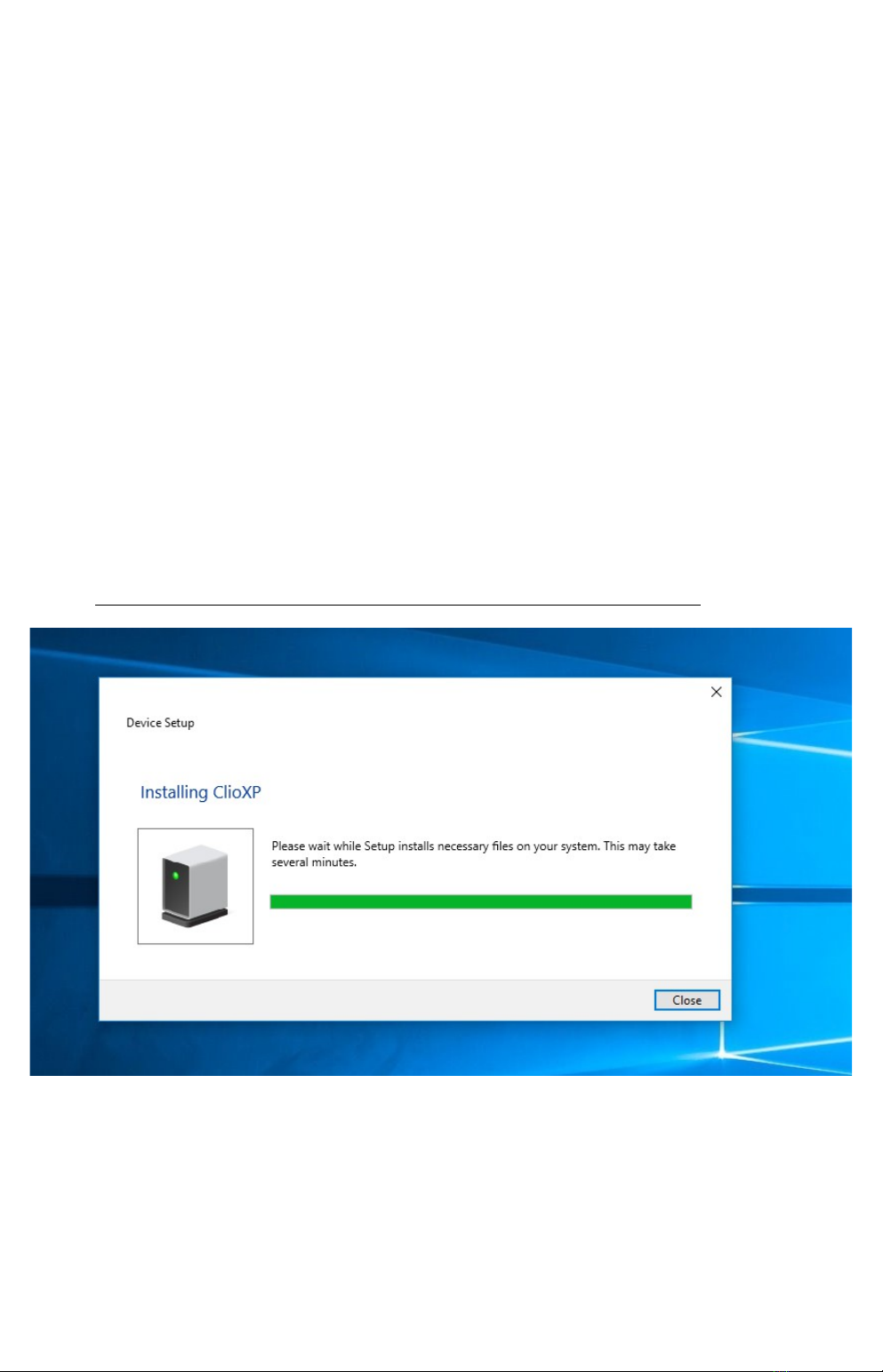
1) Connect the FW-02 to a free USB 2.0 port on your PC an power it with its 12V
supply. You shoul hear the classical soun of plug an play evices.
NOTE: ClioXP is the nickname of the FW-02 evice seen by Win ows.
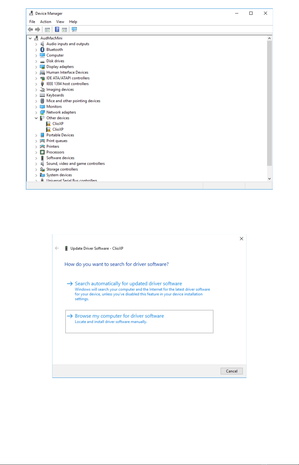
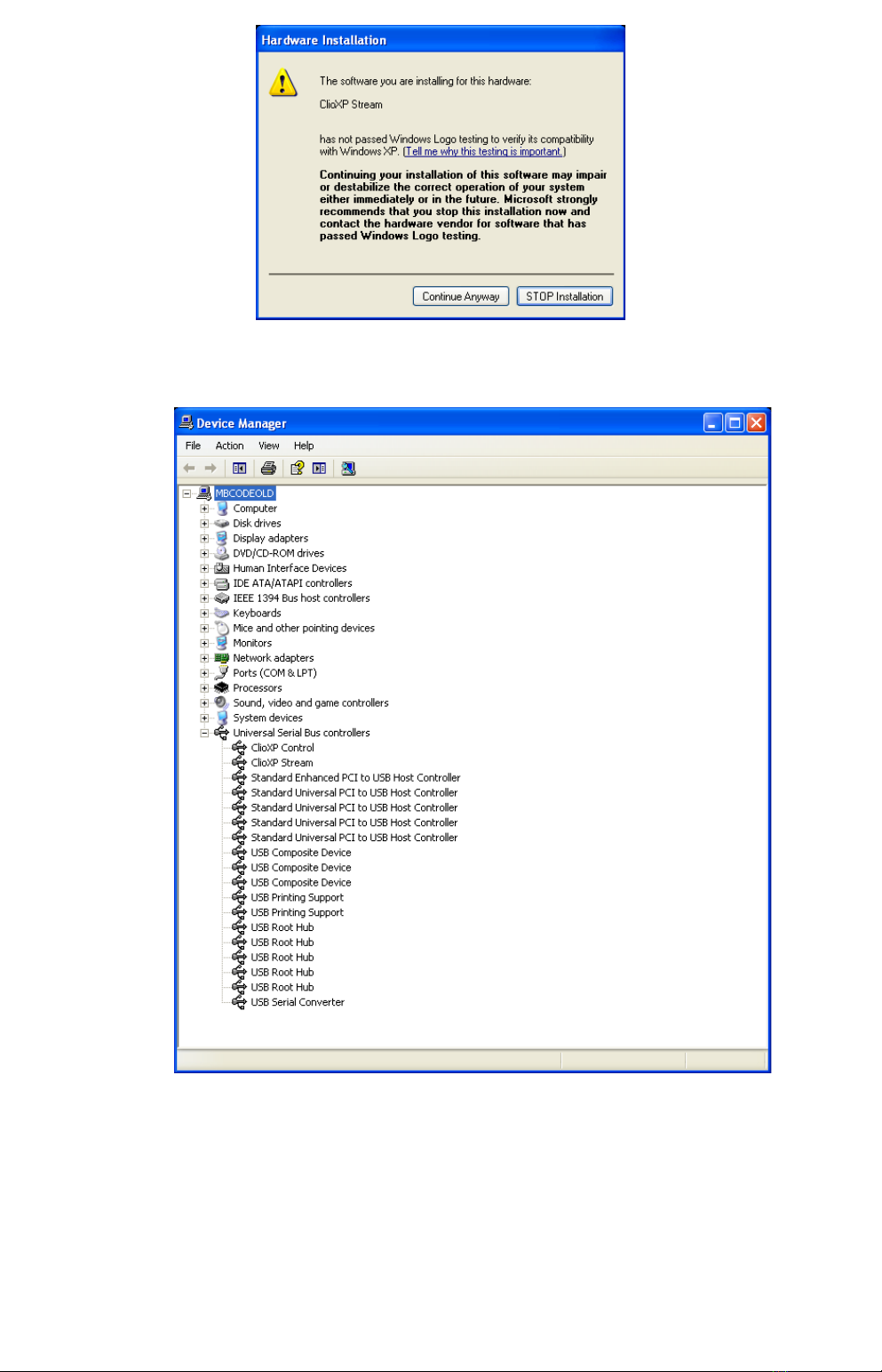
2) After the initial automatic river etection only one evice shoul be foun am
properly installe by Win ows, the USB Composite Device; two more evices,
name ClioXP will nee to be installe manually. Open Device Manager (type
devmgmt.msc from Run prompt or click Control Panel>System>Device
Manager); you shoul fin this situation:
3 CLIO INSTALLATION 1
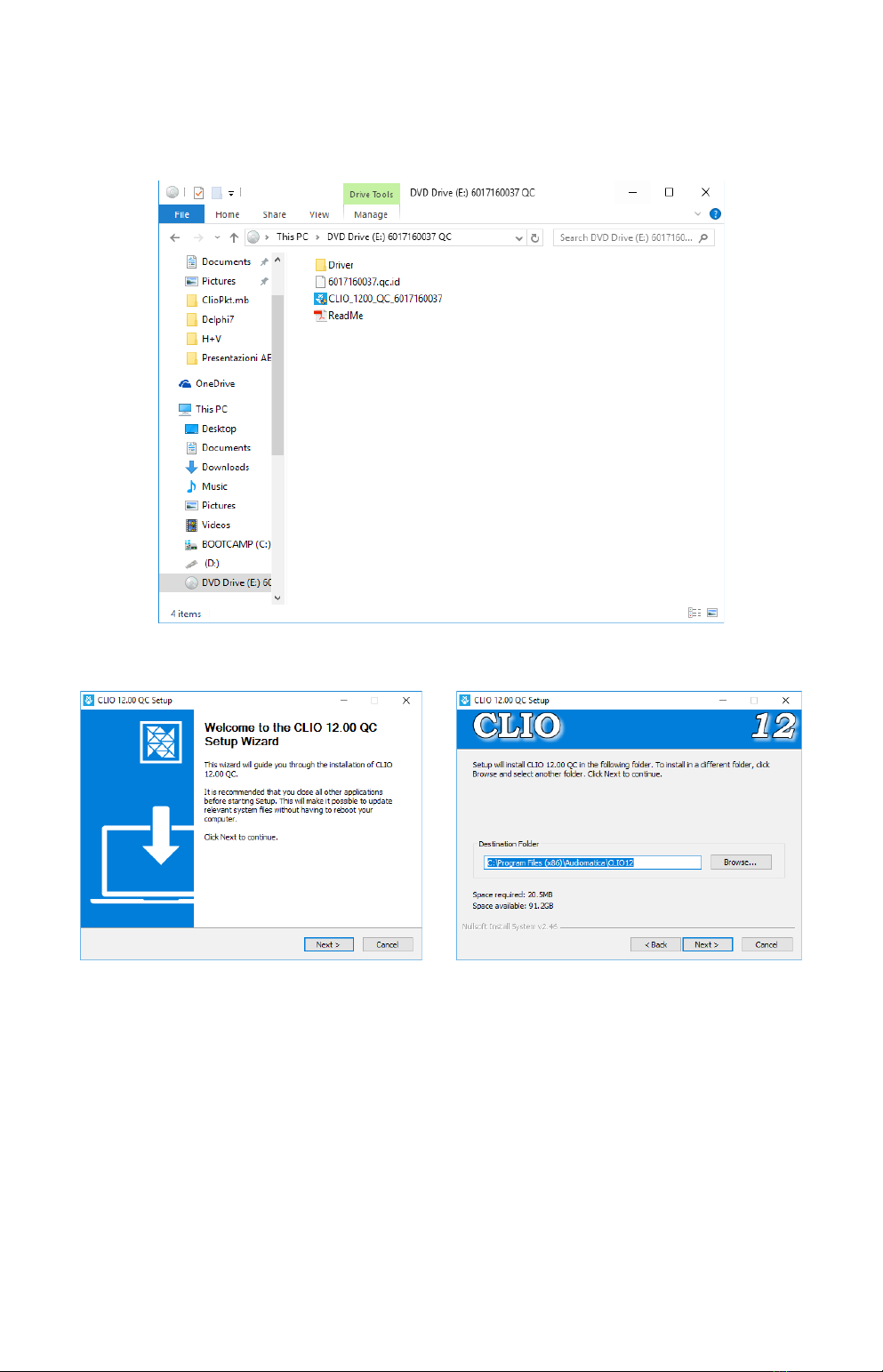
3) Insert the CLIO 12 installation CD-ROM in the PC.
4) Right-Click on each ClioXP evice un er Other Devices an choose Up ate Driver
Software. At the successive prompt:
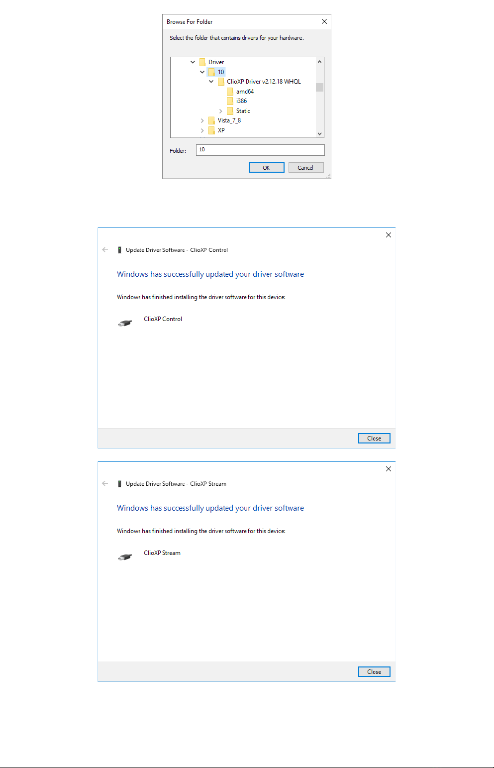
5) Browse your computer an point to the fol er insi e the installation CD where
the proper rivers are locate (for example \Driver\10).
2 3 CLIO INSTALLATION
Ignore any Microsoft's warning message about Digital Signature or Publisher an
reach the en of the wizar .
6) Inspecting again the Device manager confirms you the proper ClioXP Control an
ClioXP Stream entries un er USB controllers category:
3 CLIO INSTALLATION 3

You d ive installation was successful!
3.3 FW-02 DRIVERS INSTALLATION UNDER WINDOWS XP
1) Connect the FW-02 to a free USB 2.0 port on your PC an power it with its 12V
supply. You shoul hear the classical soun of plug an play evices.
NOTE: ClioXP is the nickname of the FW-02 evice seen by Win ows.
2) The Foun New Har ware Wizar etects the CLIO XP evice:
As the CLIOXP rivers are unknown to Win ows you will be prompte with this
search win ow:
4 3 CLIO INSTALLATION
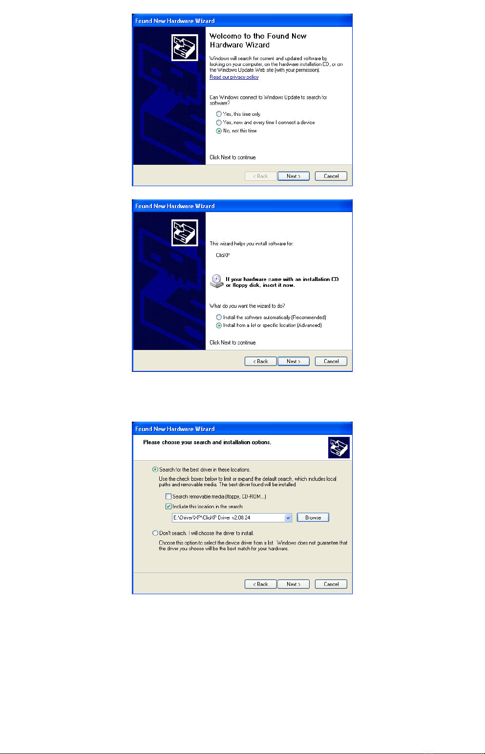
3) Insert the CLIO 12 installation CD-ROM in the PC.
Search in the proper CD fol er (for example Drivers\XP)
5) Do not stop to Microsoft Warning about Win ows Logo testing.
3 CLIO INSTALLATION 5
6) Open Device Manager (type devmgmt.msc from Run prompt or click Control
Panel>System>Device Manager); you shoul fin this situation:
You d ive installation was successful!
3.5 SOFTWARE INSTALLATION
This paragraph eals with softwa e installation.
Be su e to have administ ative ights when installing CLIO.
The CLIO software is provi e either on its own CD-ROM, SD car or, in electronic
6 3 CLIO INSTALLATION
format, as a single, self-extracting, executable file.
To install the CLIO 12 software in your computer you shoul follow the instructions
presente below:
1) Insert the CLIO 12 CD ROM in the computer.
3) Choose CLIO 12 installer to start installation.
The proce ure is completely automatic an will only request you to accept the
Software En User's License Agreement an input some information in or er to
correctly install CLIO 12; the software installer will also check your operating
system version.
After successfully completing this proce ure take note of the installation irectory
of CLIO (usually C:\Program Files\Au iomatica\CLIO12 or C:\Program Files
(x86)\Au iomatica\CLIO12 ).
3 CLIO INSTALLATION 7
3.6 RUNNING CLIO FOR THE FIRST TIME
If you have complete the prece ing installation proce ure, you are rea y to run
CLIO!
3.6.1 THE 'CLIO BOX' AND CLIO SERIAL NUMBER
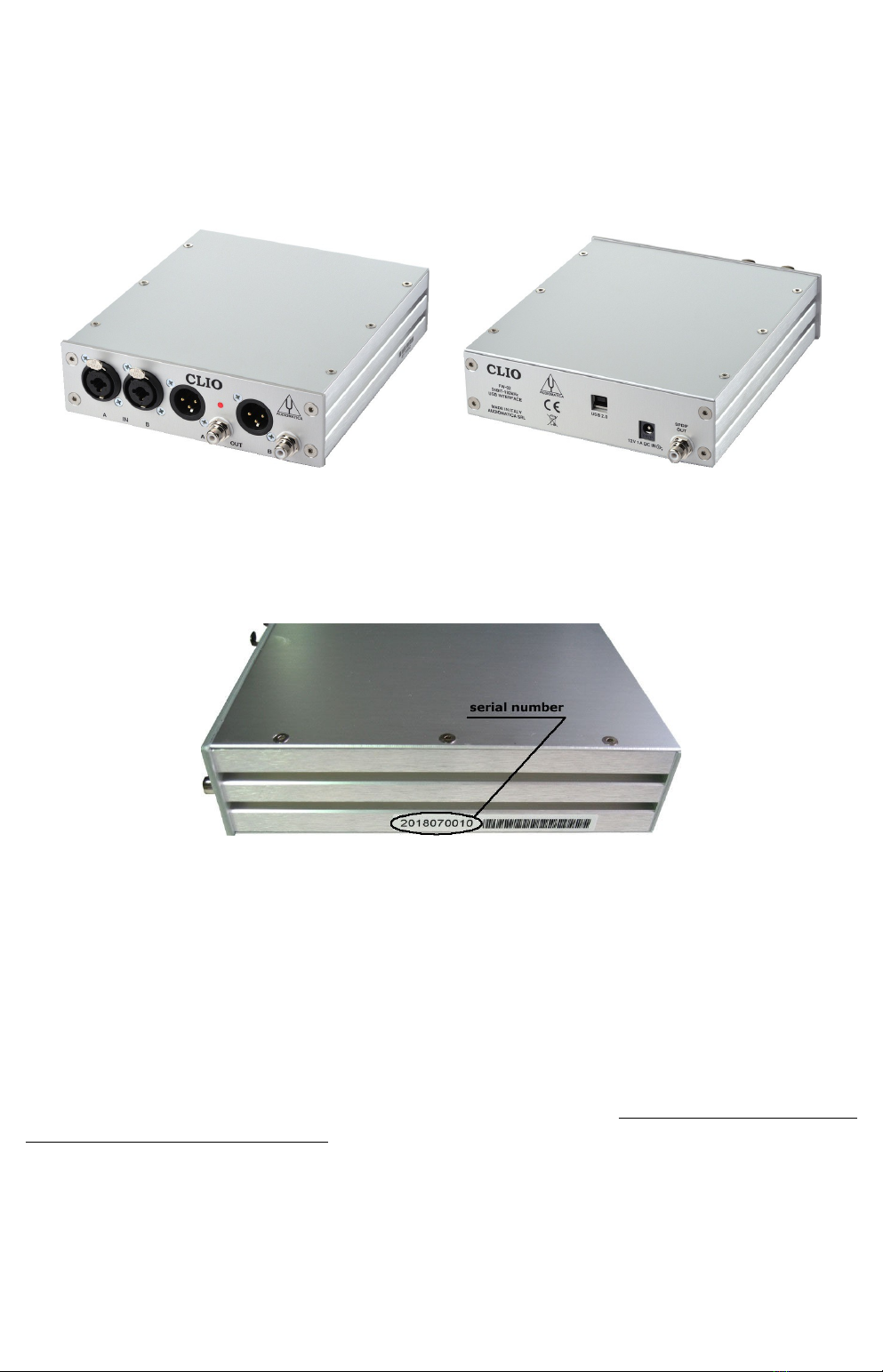
A few wor s about the FW-02 USB interface.
This unit is nee e to correctly interface analog signals to your PC; it is also
important as it has an internal reference use to calibrate the system an also
stores the system's serial number insi e its internal EEPROM; Figure below shows
where is locate your CLIO system serial number.
The CLIO se ial numbe is ve y impo tant and should be mentioned each
time you get in contact with Au iomatica, either for technical support or for
software upgra e.
Also the CLIO system accessories have their serial numbers; keep track of those
but mention to technical support ONLY UPON REQUEST.
When using your CLIO system you will normally use the FW-02 front connectors. As
you'll become extremely familiar with this har ware unit we are going to give it a
nickname: from now on we will call it 'the CLIO Box'. Also the CLIO software
refers to it with this nickname.
8 3 CLIO INSTALLATION
3.6.2 THE FIRST RUN
The following steps will guide you th ough a complete ve ification of the
system pe fo mance and ope ation.
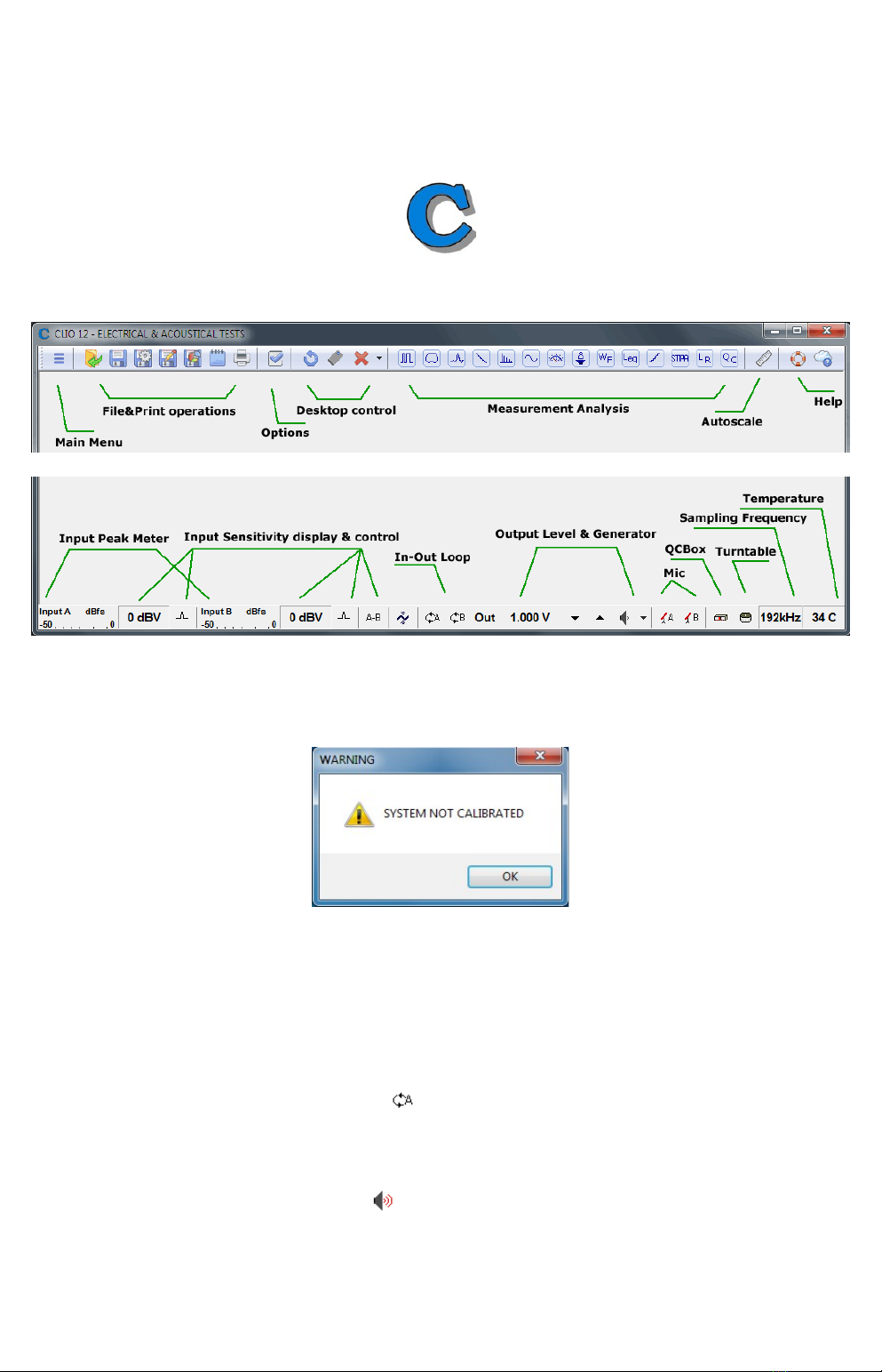
From the Sta t Menu choose P og ams, then CLIO 12 an click on the CLIO icon.
The program shoul start smoothly an present the main esktop.
If the system is not calibrate , as the first time you run it, you will receive the
following message.
Shoul CLIO isplay an error message take note of it an go to the troubleshooting
section.
3.6.3 INITIAL TEST MEASUREMENT
Let's now execute our first test measurement - play an capture a 1kHz sinusoi .
First of all click on the In-Out Loop button for channel A; in this way the CLIO
Box connects output A with input A with an internal relay. This connection is very
important as it lets you capture an analyze a signal generate by CLIO without the
nee for an external connecting cable.
Then click on the generator icon to play the 1kHz sinusoi (1031.25Hz to be
exact; more on this later, it's the efault signal). Then press the F4 keystroke to
invoke the Multi-Meter as in Figure.
3 CLIO INSTALLATION 9
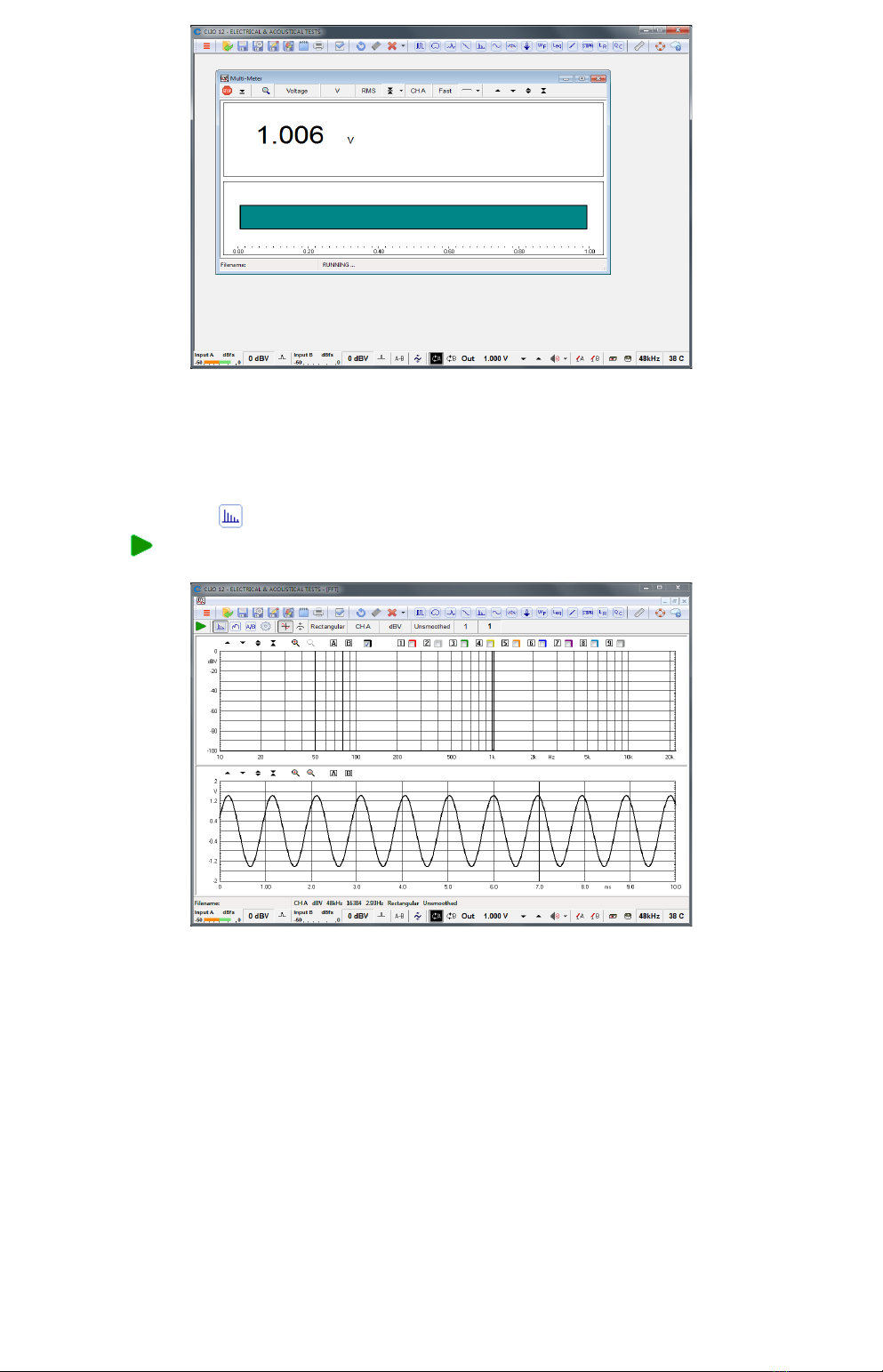
If everything is OK you shoul obtain a rea ing of circa 1V, variable between a
minimum of 0.95V an a maximum of 1.05V, which is the mean output level of a
sinusoi al signal when the system is not calibrate .
Now press the FFT button (or CTRL-F), then press the Oscilloscope button an
finally the GoButton.
The result you shoul obtain is an FFT analysis of the 1kHz sinusoi (one spectral
line @ 1kHz at 0 BV) an its time representation given by its oscillogram.
Both Multimeter an FFT results must present stable an repeatable; the
oscillogram shoul isplay a sinusoi without spikes or rops of any kin .
IMPORTANT NOTE: Only if these two initial tests gave correct results, as
escribe , go to the following paragraph an execute the system calibration; if you
are not able to obtain these results an they seem in any way corrupte do not
execute calib ation an contact technical support.
10 3 CLIO INSTALLATION
3.7 SYSTEM CALIBRATION
This section escribes how to perform the system calibration.
Be sure that, any time you perform a calibration, the system has warme up for, at
least 15-20 minutes.
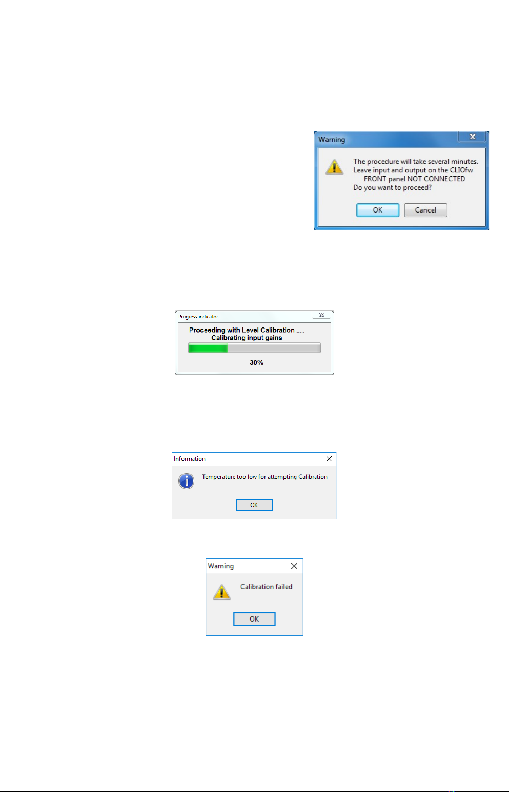
Select Calib ation from the Main menu ;
Leave the CLIO Box f ont plugs unconnected.
Answer OK to the initial prompt; this will run an automatic proce ure that will last
several minutes. The calibration proce ure is completely automatic an several
progress in icators will accompany all the execute measurements. At the en of it
your CLIO system shoul be calibrate an rea y to carry out measurements.
Software won't allow calibration if inte nal tempe atu e lies outsi e a
pre etermine range (between 30 to 45 egrees).
So it is normal to receive a message like:
It is also normal to receive the following message:
This is normally ue to the calibration parameters that o not match the internally
store parameters that have been measure at Au iomatica laboratory an that
ensure the highest precision of the instrument. In such a case either wait to repeat
calibration if instrument is too col for it to warm, or wait for the evice to cool if
too hot.
At the en of the calibration process it is always man atory to verify the calibration
itself; this is one by two simple measurements as escribe in the following
3 CLIO INSTALLATION 11
paragraph 3.7.1 CALIBRATION VALIDATION.
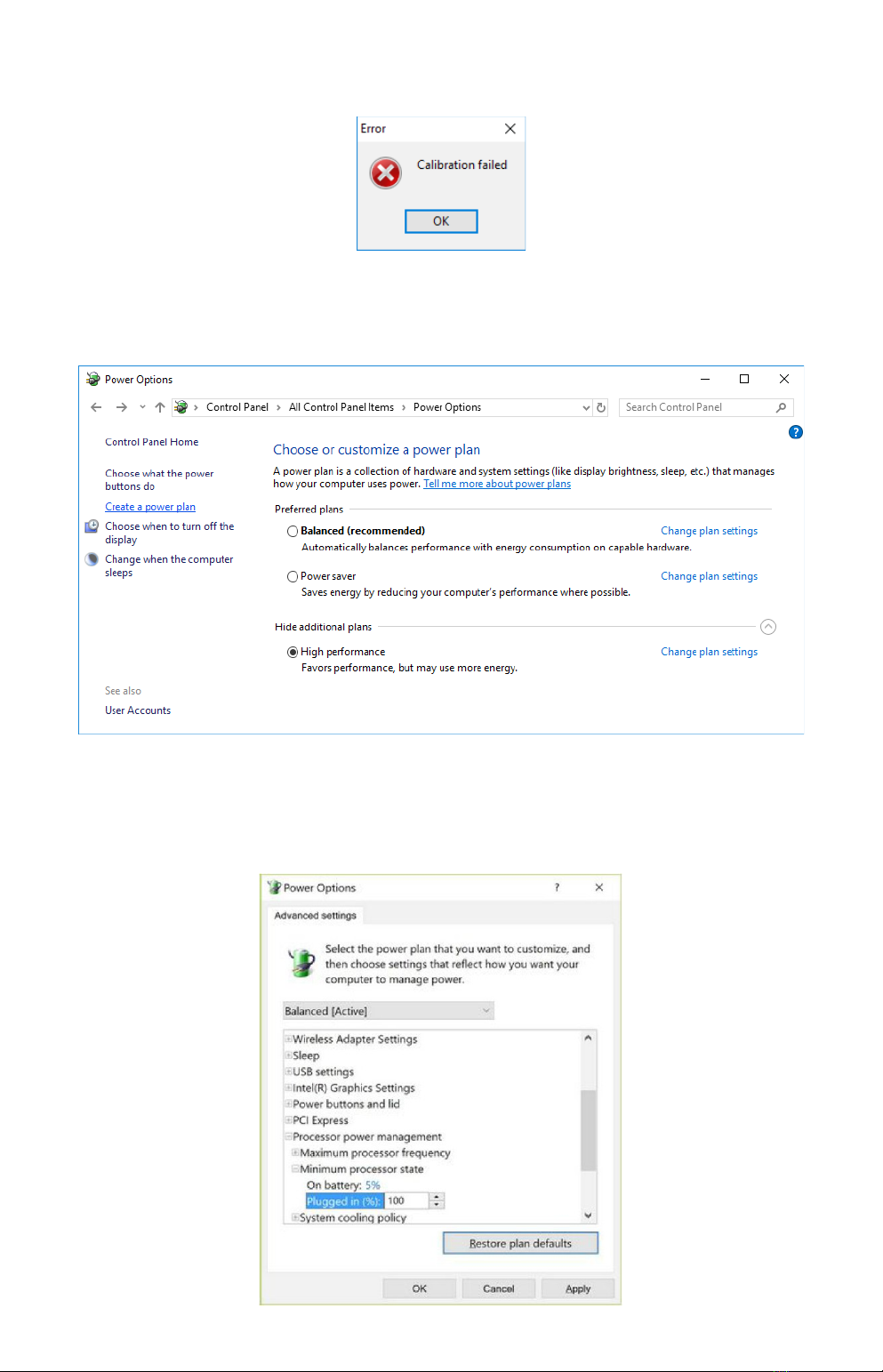
Only if this message appears consi er to take proper action:
Calibration is a computer system resources eman ing task.
Your computer woul be best operate at high performance level:
When using a notebook neve un on batte ies, always hook it to AC mains, as
power saving schemes greatly re uce performances. As ultimate resource these are
Recommen e A vance Power Settings, i.e. set 100% the Minimum processor
state:
12 3 CLIO INSTALLATION

If you are not able to perform calibration please follow proce ures given in 3.9
TROUBLESHOOTING CLIO INSTALLATION to get in contact with Au iomatica
technical support.
CLIO has been esigne to give the user a high egree of precision, while
maintaining ease of use thus ensuring confi ence in the measurements taken.
Calibration check plays a key role in all this. Note that, as calibration nee s to be
performe un er controlle con itions, calibration should be attempted the
least times possible; calibration, on the other si e, shoul be verified as nee e
or requeste all the times the user wants following instructions given next;
verification, not calibration, of your har ware gives maximum confi ence when
taking measurements.
3.7.1 CALIBRATION VALIDATION
To verify the calibration, first check that the generator output level is set to 1V
(refer to chapter 4 for etails).
Press the channel A In-Out Loop button .
Then click on the MLS&LogChirp button to invoke the MLS&LogChirp control
panel. Press the Go button to execute a LogChirp frequency response
measurement; after about 1 second you shoul obtain the esire result, a
straight line (black) as in Figure. You can click on the graph an inspect the
amplitu e of the measure signal: you shoul obtain a rea ing aroun 0 BV, this is
the correct output level of the LogChirp signal with the generator output set to 1V.
Now click on the Sinusoi al button to invoke the Sinusoi al control panel as in
Figure. Press the Go button to execute a Sinusoi al frequency response
measurement; after about 3 seconds you shoul obtain the esire result, again a
straight line (black) as in Figure. You can click on the graph an inspect the
amplitu e of the measure signal: you shoul obtain a rea ing aroun 0 BV.
3 CLIO INSTALLATION 13

To ensure a 100% correct calibration you also nee to inspect the phase responses
of both measurements. To o this press the phase button an verify that you
obtain a straight line (re curves) the rea ings in this case shoul be aroun zero
egrees in both cases.
As a final test click on the In-Out Loop button for channel A; then click on the
In-Out Loop button for channel B; then be sure that both input sensitivity are at
0 BV; click on the generator icon to play the 1kHz sinusoi ; at last press the F4
keystroke to invoke again the Multi-Meter; the expecte result is shown now.
14 3 CLIO INSTALLATION
3.8 CLIO SERIAL NUMBER AND DEMO MODE
Each CLIO system has its own se ial numbe which plays an important role since
the CLIO software is har ware protecte an relies on a correct serialization in
or er to run.
Refer to 3.6 to i entify your system's serial number.
If the CLIO software oesn't fin a CLIO Box with a correct serial number it gives a
warning message an enters what is calle DEMO mode; in this way it is possible
to run CLIO in a PC where the CLIO har ware is not installe while still allowing you
to perform post-processing an other off line jobs.
3.9 TROUBLESHOOTING CLIO INSTALLATION
To receive assistance please contact Au iomatica at support@au iomatica.com or
connect to our website www.au iomatica.com.
NEVER FORGET TO SIGNAL PROPER SERIAL NUMBER OF YOUR CLIO!
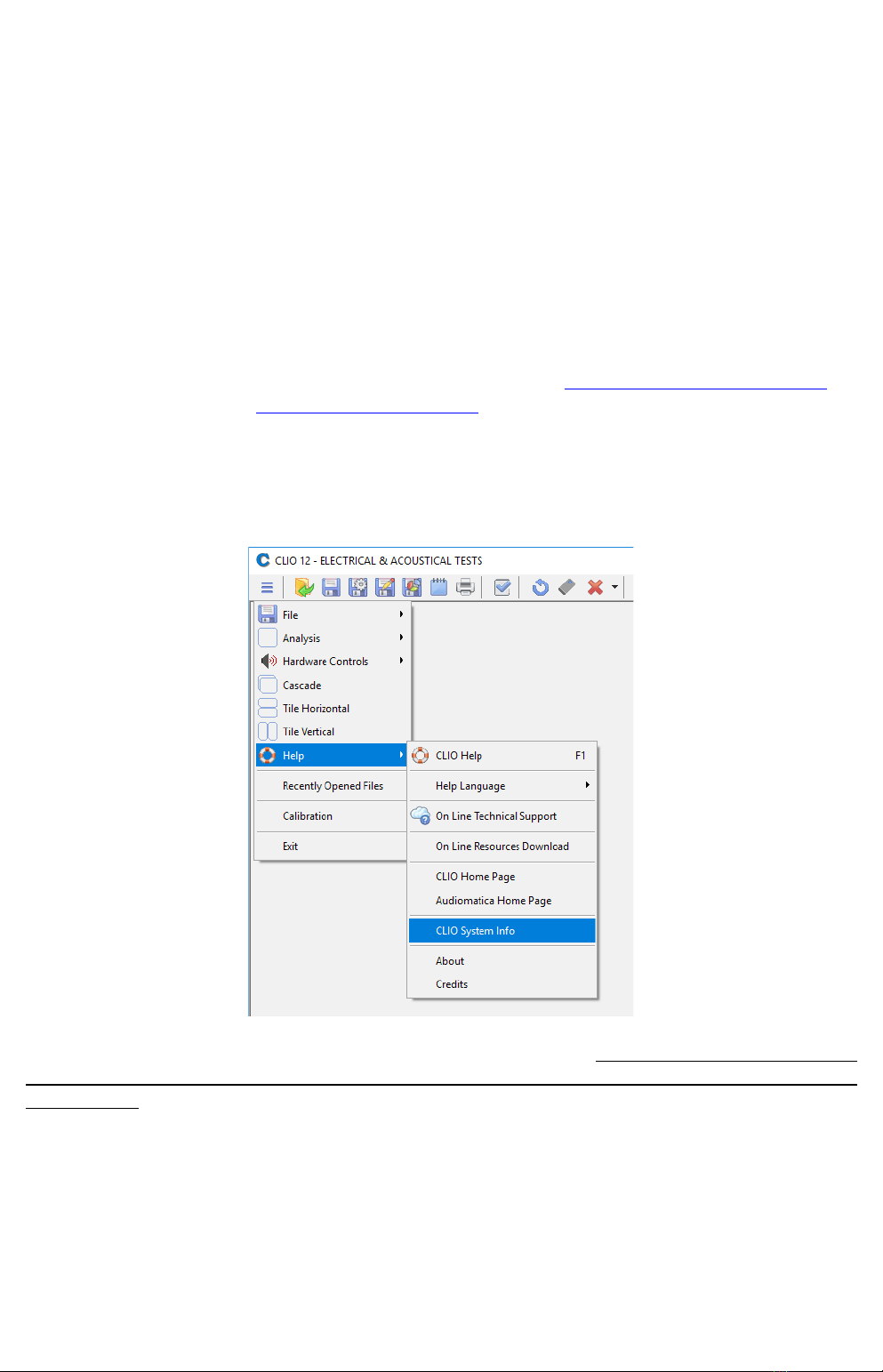
When getting in contact with us please always sen , as attachment to your email,
the System Info file of your CLIO system.
To create this file choose MainMenu>Help>SystemInfo. If you system has not
completed calib ation c eate the system info file ight afte the calib ation
has failed.
3 CLIO INSTALLATION 15
Table of contents


