Audiopole PX 500 User manual
PX 500
USER’S MANUAL
POWER AMPLIFIER

1
Safety instructions …………………………………………………………………….. 2
1. Introduction ……………………………………………………………………….. 3
2. Features………………………………………………………………………….… 3
3. Controls and Settings…………………………………….…………………….… 4
4. Operating Modes ……………………………………………………………….… 6
5. Installations ints …..…………………………………….………………………. 6
6. Connectors ….…………………………………………………………………..… 8
7. Impedance Load ………………………………………………………….….…… 8
8. Technical Specifications…..………………………………………………..….…. 9
9. Malfunctions ……..……………………………………………………..……..….. 10
10. Warranty …………………………………………………………………………... 10
Index

POWER SUPPLY
Ensure that the insource voltage (AC outlet) matches the voltage rating of the product. Failure to do so could
result in damage to the product and possibly the user. Unplug the product before electrical storms occur and
when unused for long periods of time to reduce the risk of electric shock or fire.
2
EXTERNAL CONNECTION
Always use proper ready-made insulated mains cabling (power cord). Failure to do so could result in
shock/death or fire. If in doubt, seek advice from a registered electrician.
FUSE
To prevent fire and damage to the product, use only the recommended fuse type as indicated in this manual. Do
not short-circuit the fuse holder. Before replacing the fuse, make sure that the product is OFF and disconnected
from the AC outlet.
PROTECTIVE GROUND
Before turning the unit on, make sure that it is connected to Ground. This is to prevent the risk of electric shock.
Never cut internal or external Ground wires. Like wise, never remove Ground wiring from the Protective Ground
Terminal.
OPERATING SAFETY INSTRUCTIONS
Read these instructions. Follow all instructions. Keep these instructions. Do not discard. eed all warnings. Only
use attachments/accessories specified by the manufacturer.
This symbol indicates that the disposal of this product is submitted to local regulations. Please
contact your local dealer.
DISPOSAL
Important Sa ety Instructions
This symbol, wherever used, alerts you to the presence of un-insulated and dangerous voltages
within the product enclosure. These are voltages that may be sufficient to constitute the risk of
electric shock or death.
This symbol, wherever used, alerts you to important operating and maintenance instructions.
DO NOT REMOVE ANY COVERS
Within the product are areas where high voltages may present. To reduce the risk of electric shock do not
remove any covers unless the AC mains power cord is removed. Covers should be removed by qualified service
personnel only. No user serviceable parts inside.
POWER CORD AND PLUG
Do not tamper with the power cord or plug. These are designed for your safety. Do not remove Ground
connections! If the plug does not fit your AC outlet seek advice from a qualified electrician. Protect the power
cord and plug from any physical stress to avoid risk of electric shock. Do not place heavy objects on the power
cord. This could cause electric shock or fire.
SERVICING
Refer all servicing to qualified service personnel only. Do not perform any servicing then those instructions
contained within this User’s Manual

Introduction
3
1
Features
2
Thank you for purchasing Audiopole PX 500. This professional class-D amplifier delivers 500 W and only
weighs 3.7 kg in one unit rack.
PX 500 offers 3 different modes. STEREO mode is a stereo amplification who can provide 2 x 180 W / 8 Ohms
or 2 x 250 W / 4 Ohms. BRIDGE mode provides 500 W / 8 Ohms. PARALLEL mode amplifies a mono source,
using resources from 2 channels.
The device features a choice of connectors that adapt easily to most uses. Balanced XLR inputs are doubled
by unbalanced RCA jacks and the speaker outputs use binding post terminals.
•2 x 180 W / 8 Ohms, 2 x 250 W / 4 Ohms
•500 W / 8 Ohms (BRIDGE mode)
•Class-D amplification
•3 operating modes : STEREO – BRIDGE – PARALLEL
•Balanced XLR inputs, Unbalanced RCA inputs
•Output binding post terminals
•One unit rack mount (1U)
•3.7 kg

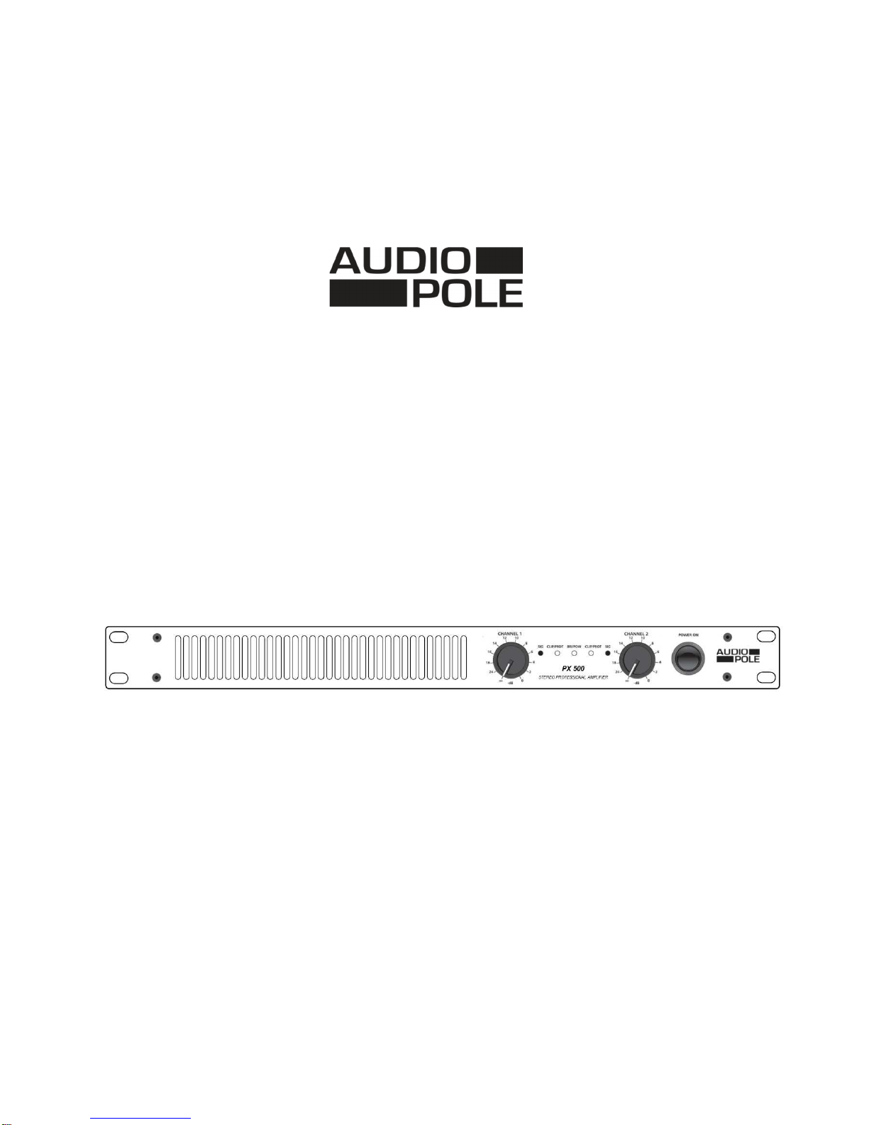
4
1 – POWER ON
When the power switch is activated the soft start mode operates, muting the outputs to prevent damages to the
speakers. The delay times before switching on is 7 s.
2 – CHANNEL 1
Channel 1 level control. Increase the level by turning the knob in a clockwise direction.
3 – CHANNEL 2
Channel 2 level control. Increase the level by turning the knob in a clockwise direction.
4 – SIG
Channel 1 signal indicator. The intensity of the Green Led varies depending on the level of the input signal.
5 – SIG
Channel 2 signal indicator.
6 – CLIP/PROT
Channel 1 clipping and protect mode indicator.
The red Led provides information about the input signal status. Normally, it should light up occasionally. If it
illuminates more than occasionally, it means that the input level is too important and there is a risk of distortion.
Then, adjust the level with the attenuators (2) and (3) or decreases the source volume.
In case of constant lighting and absence of sound, the channel is in protection mode, meaning that some
problems has occurred (refer to paragraph 9).
7 – CLIP/PROT
Channel 2 clipping indicator.
8 – BRI POW
BRIDGE mode and power indicator.
The two-color LED lights up green when the amplifier is powered; it turns red when the BRIDGE mode is
switched on.
Front Panel
Controls and Settings
3
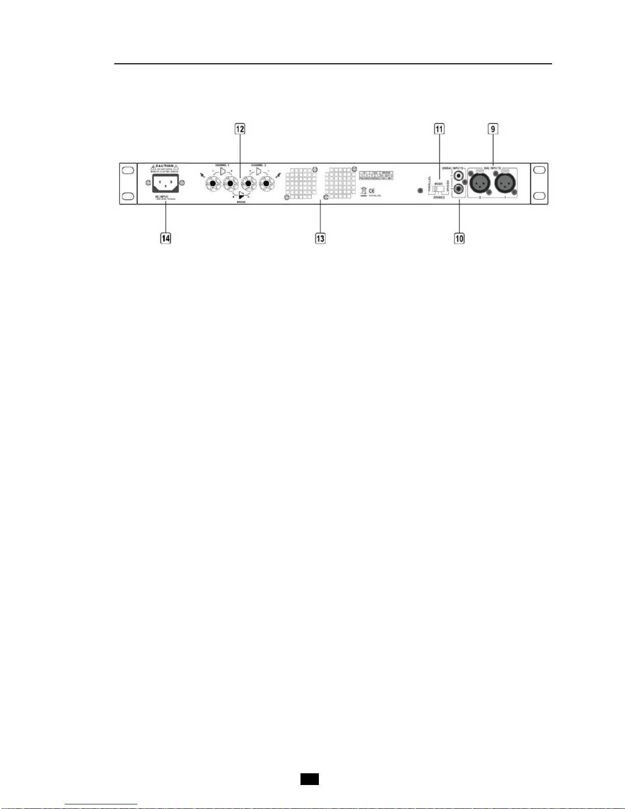
9 – BAL INPUT
XLR balanced inputs 1 & 2.
10 – UNBAL INPUTS
RCA unbalanced inputs 1 & 2.
11 – MODE
Mode selector : PARALLEL – STEREO – BRIDGE (see Chapter 4)
Please turn off the device before any actions.
12 – CHANNEL OUT
Output binding post terminals for speaker connection.
13 – Ventilation
Cooling fans. Do not obstruct the entries and exits of air for the cooling of the amplifier. Any impediment to the
free movement of air in the amplifier may cause a failure not covered by the warranty.
14 – AC INPUT
Power outlet. Before any connections make sure that the power cable is not damaged. The connection to the
mains supply must have an earth connection. The mains voltage supplied must conform with the electrical
characteristics of the appliance (see Chapter 8).
Controls and Settings
5
3
Rear Panel
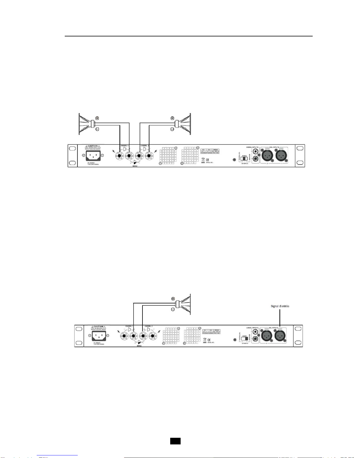
BRIDGE Mode
It is a monophonic mode, both channels work with the same signal input, but in phase opposition. It follows a
voltage output multiplied by two, and therefore issued two times more power on double load impedance.
ONLY channel 1 is used. The input signal is connected to input 1, both volume controls remain operating and
must be positioned on the same value: position 0 dB is recommended (at bottom right).
Be care ul with the wiring, speakers are connected to the red terminal of the binding post. Check that the load
impedance is not less than 8 Ohms (see Chapter 7).
Operating Modes
6
4
STEREO Mode
This is the standard mode: both channels functioning independently, the attenuators (2) and (3) respectively
controlling each channel input levels. The recommended nominal load impedance is 8 or 4 Ohms per channel.
The speakers are connected to the terminals as shown in the figure below.
Operating Modes
7
4
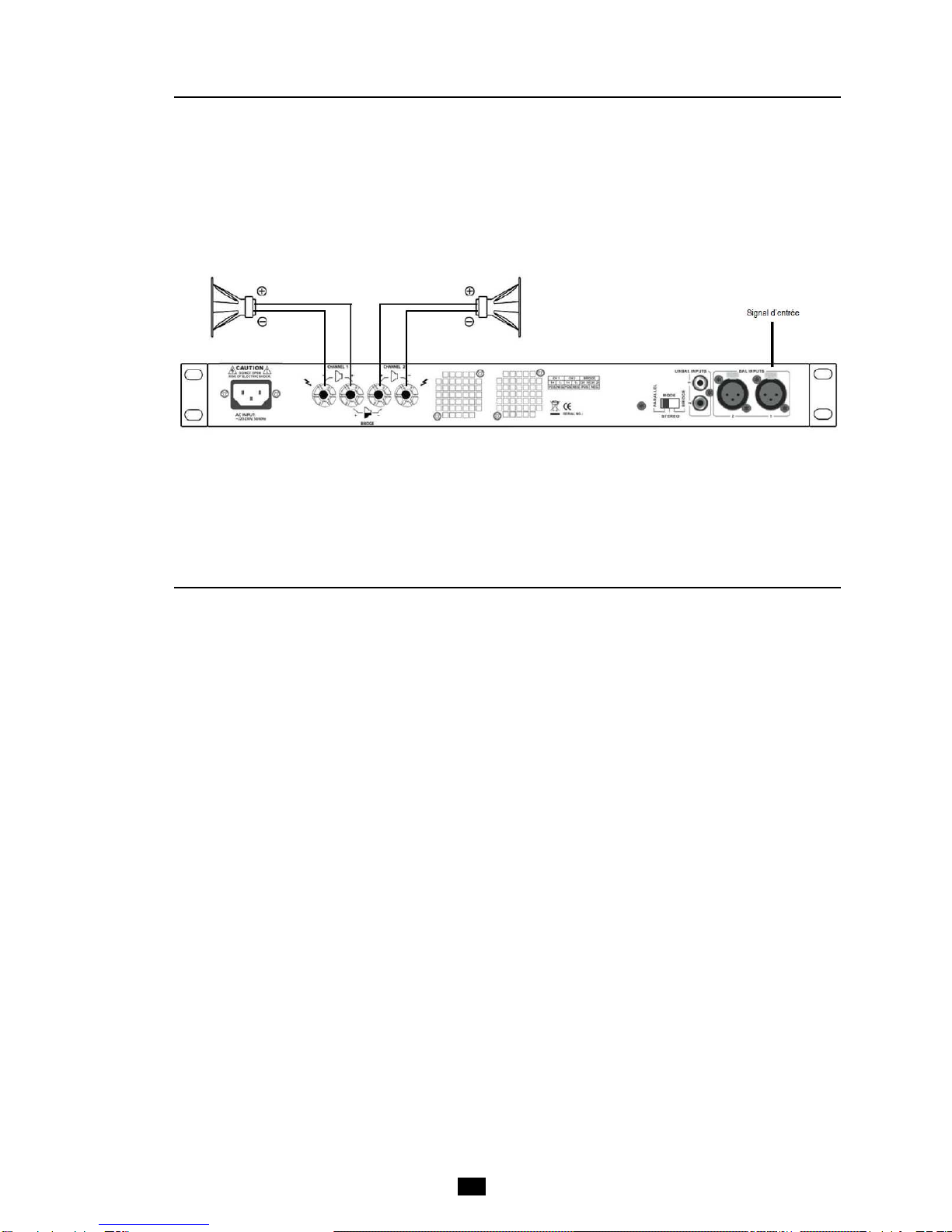
PARALLEL Mode
In this mode both channels of the amplifier receive the same signal connected to the input 1, both attenuators
(2) and (3) remaining active. The speaker outputs wiring is identical to Stereo mode.
Installations Hints
5
In case of installation in cabinet or rack, ensure the ventilation requirements.
The depth of the device is 277 mm, the height is 1 unit rack (44 mm).
Do not position high-gain audio equipment like preamplifiers or recorders just above or below the amplifier.
Despite the protections of the radiation device, magnetic fields can induce hum in unscreened ancillary
equipment.
Do not obstruct the entrance and exits of air for the cooling of the amplifier. Any impediment to the free
movement of air in the amplifier may cause a failure not covered by the warranty.
The amplifier use in an environment where the air is confined or polluted requires frequent internal cleaning.
Smoke and dust particles accumulated inside the appliance can cause failures not covered by the warranty.
This cleaning should be done by qualified personnel.
Before any work on the wiring, be sure to turn the control knobs fully counterclockwise and turn off the
amplifier.
Only use good quality speaker cables, unshielded.
Use good quality audio cables, shielded, for inputs. A balanced connection is recommended to keep a signal
without degradation.
8
Connectors
6
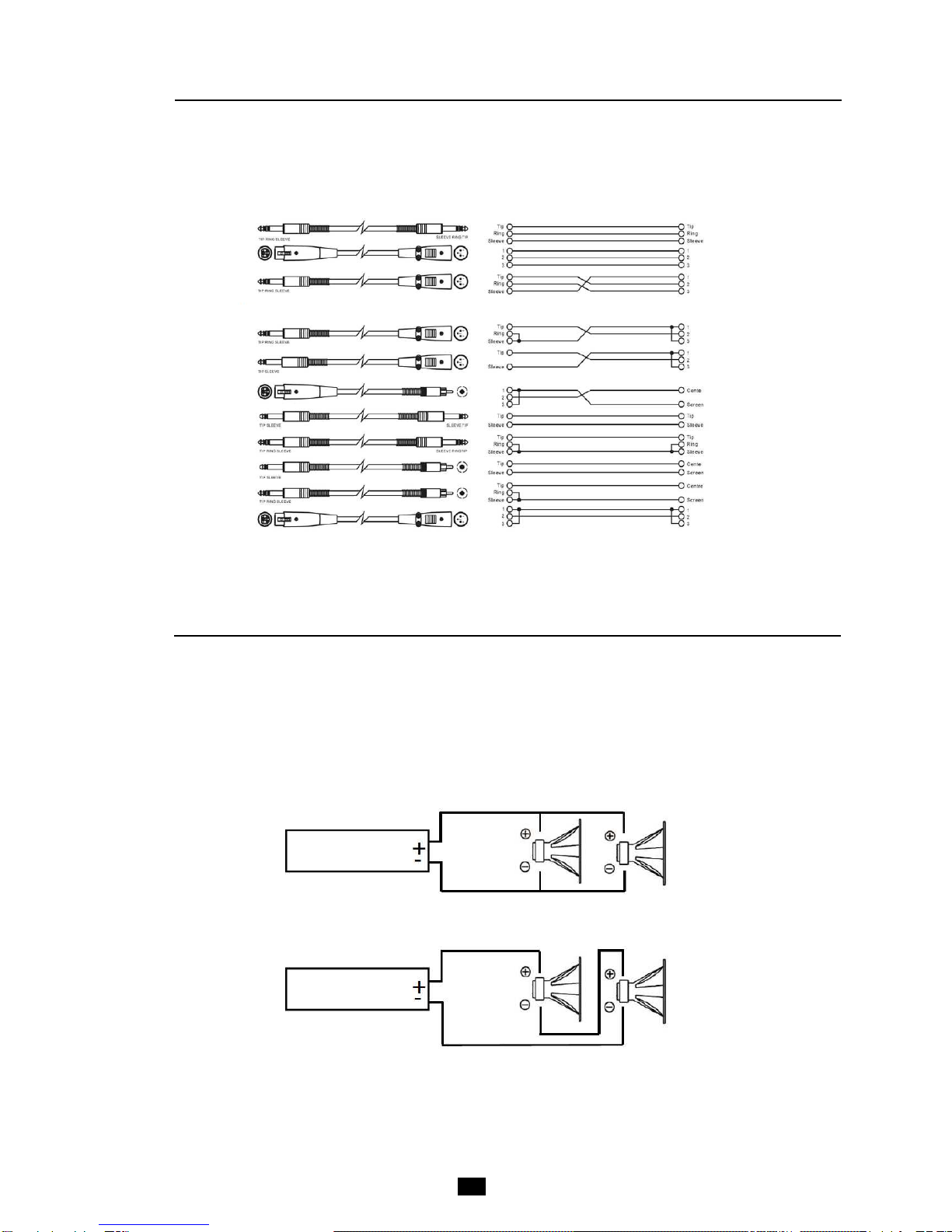
PX 500 input connectors are balanced (XLR) and unbalanced (RCA). Cables related to connecting to other
equipment must therefore be of the same nature. Are listed below types of different cords with their electrical
connection diagram.
Balanced
Unbalanced
Impedance load
When connecting multiple speakers or speakers on the same channel, various types of connection are possible.
The type of installation changes the impedance of the load applied to the amplifier. Generally, when this
impedance decreases the power increases. It is therefore possible to obtain a greater power, but this is limited
by the characteristics of the amplifier. Knowledge of the load impedance is therefore crucial in order to not cause
trouble.
Serial mode
7
AMPLIFIER
AMPLIFIER
Parallel mode (most common !)

Impedance load
9
7
The table below gives the value of the total impedance depending on the connection modes. It only includes
the most frequently encountered cases.
Technical Speci ications
8
8 Ohms : 180 W
4 Ohms: 250 W
8 Ohms : 500 W (BRIDGE mode)
Class Class-D
THD 0,05%
S/N ratio > 65 dB
Slew rate 5 V / µs
Damping actor 300
Operating Modes STEREO / PARALLEL / BRIDGE
Cross talk > 46 dB
So t start 7 sec
Input sensitivity 0,7 V
Frequency response 20 z - 20 k z @ ± 0,25 dB
• XLR balanced
• RCA unbalanced
Output connectors Binding post
So t start Yes
Power supply ~ 220-230 V, 50/60 z
Dimensions (L x P x H) 483 x 277 x 44 mm
Net weight 3.7 kg
Power (per channel)
Input connectors
Speaker impedance Speaker quantity (*) Equivalent impedance o
PARALLEL Mode
Equivalent impedance o
SERIAL Mode
16 Ohms 2 8 Ohms 32 Ohms (not recommended)
4 4 Ohms 64 Ohms (not recommended)
8 Ohms 2 4 Ohms 16 Ohms
4 2 Ohms (do not use) 32 Ohms (not recommended)
4 Ohms 2 2 Ohms (do not use) 8 Ohms
4 1 Ohm (do not use) 16 Ohms

10
Mal unctions
22, rue Édouard Buffard, Z.A.C. de la Charbonnière, Montévrain - 77771 Marne-la-Vallée Cedex 4 - France
Tél : + 33 (0)1 60 54 32 00 - Fax : + 33 (0) 1 60 54 31 90 - www.audiopole-pa.fr
9
Warranty
10
This device is warranted parts and labor against any manufacturing defects for a period of two years from the
date of purchase by the first user.
Conditions
1. The unit has been installed and implemented by observing the safety instructions in this operating manual.
2. The device was not diverted from its destination, either voluntary or accidental, and suffered no
deterioration or modification other than those described here or explicitly authorized by AUDIOPOLE.
3. All modifications or repairs have been carried out by an authorized service station.
4. The defective product must be returned with the dealer who made the sale or to an authorized service
station with proof of purchase.
5. The device was properly packaged to avoid damage in transport.
Symptom Cause Solution
No power •The mains cable is not correctly connected or is
faulty.
•The power switch is not pressed.
•Reconnect the power cord.
•Change the cord.
•Turn the switch ON.
No sound on one or more
channels •The volume is at a minimum.
•Speakers are not connected.
•One or more input signals are not connected or
their level is at zero.
•The MODE switch is positioned improperly.
•The PROT indicator is on.
•Adjust the volume.
•Connect speakers.
•Connect inputs and adjust the
levels of the other equipment.
•Modify selection.
•Check speaker lines and
connections polarity
Saturated sound Inappropriate input signal level. Adjust levels and gains and the
equalization of the other equipment.
um Bad ground or faulty power supply. Check the mains voltage.
Some occasional problems are very often linked to handling errors. By checking the points listed below, it will
be possible to find without difficulty, solutions to potential malfunctions. If problems persist, consult a dealer or
an authorized AUDIOPOLE service center.
Table of contents
Other Audiopole Amplifier manuals

Audiopole
Audiopole PA 225 User manual

Audiopole
Audiopole A 241 User manual

Audiopole
Audiopole PX-140 User manual

Audiopole
Audiopole FORCE 700 User manual

Audiopole
Audiopole ZONER 4-120 User manual

Audiopole
Audiopole PX3 User manual

Audiopole
Audiopole PA 4-250 User manual

Audiopole
Audiopole CLIMAX 1002 User manual

Audiopole
Audiopole PX-360 User manual

Audiopole
Audiopole CLIMAX 3200 DSP User manual


